EP0650602B1 - Ensemble de connexion pour fibre optique - Google Patents
Ensemble de connexion pour fibre optique Download PDFInfo
- Publication number
- EP0650602B1 EP0650602B1 EP94912364A EP94912364A EP0650602B1 EP 0650602 B1 EP0650602 B1 EP 0650602B1 EP 94912364 A EP94912364 A EP 94912364A EP 94912364 A EP94912364 A EP 94912364A EP 0650602 B1 EP0650602 B1 EP 0650602B1
- Authority
- EP
- European Patent Office
- Prior art keywords
- plug
- jack
- assembly
- housing
- ferrule
- Prior art date
- Legal status (The legal status is an assumption and is not a legal conclusion. Google has not performed a legal analysis and makes no representation as to the accuracy of the status listed.)
- Expired - Lifetime
Links
Images


Classifications
-
- G—PHYSICS
- G02—OPTICS
- G02B—OPTICAL ELEMENTS, SYSTEMS OR APPARATUS
- G02B6/00—Light guides; Structural details of arrangements comprising light guides and other optical elements, e.g. couplings
- G02B6/24—Coupling light guides
-
- G—PHYSICS
- G02—OPTICS
- G02B—OPTICAL ELEMENTS, SYSTEMS OR APPARATUS
- G02B6/00—Light guides; Structural details of arrangements comprising light guides and other optical elements, e.g. couplings
- G02B6/24—Coupling light guides
- G02B6/36—Mechanical coupling means
- G02B6/38—Mechanical coupling means having fibre to fibre mating means
- G02B6/3807—Dismountable connectors, i.e. comprising plugs
- G02B6/389—Dismountable connectors, i.e. comprising plugs characterised by the method of fastening connecting plugs and sockets, e.g. screw- or nut-lock, snap-in, bayonet type
- G02B6/3893—Push-pull type, e.g. snap-in, push-on
-
- G—PHYSICS
- G02—OPTICS
- G02B—OPTICAL ELEMENTS, SYSTEMS OR APPARATUS
- G02B6/00—Light guides; Structural details of arrangements comprising light guides and other optical elements, e.g. couplings
- G02B6/24—Coupling light guides
- G02B6/36—Mechanical coupling means
- G02B6/38—Mechanical coupling means having fibre to fibre mating means
- G02B6/3807—Dismountable connectors, i.e. comprising plugs
- G02B6/381—Dismountable connectors, i.e. comprising plugs of the ferrule type, e.g. fibre ends embedded in ferrules, connecting a pair of fibres
- G02B6/3818—Dismountable connectors, i.e. comprising plugs of the ferrule type, e.g. fibre ends embedded in ferrules, connecting a pair of fibres of a low-reflection-loss type
- G02B6/3821—Dismountable connectors, i.e. comprising plugs of the ferrule type, e.g. fibre ends embedded in ferrules, connecting a pair of fibres of a low-reflection-loss type with axial spring biasing or loading means
-
- G—PHYSICS
- G02—OPTICS
- G02B—OPTICAL ELEMENTS, SYSTEMS OR APPARATUS
- G02B6/00—Light guides; Structural details of arrangements comprising light guides and other optical elements, e.g. couplings
- G02B6/24—Coupling light guides
- G02B6/36—Mechanical coupling means
- G02B6/38—Mechanical coupling means having fibre to fibre mating means
- G02B6/3807—Dismountable connectors, i.e. comprising plugs
- G02B6/3869—Mounting ferrules to connector body, i.e. plugs
-
- G—PHYSICS
- G02—OPTICS
- G02B—OPTICAL ELEMENTS, SYSTEMS OR APPARATUS
- G02B6/00—Light guides; Structural details of arrangements comprising light guides and other optical elements, e.g. couplings
- G02B6/24—Coupling light guides
- G02B6/36—Mechanical coupling means
- G02B6/38—Mechanical coupling means having fibre to fibre mating means
- G02B6/3807—Dismountable connectors, i.e. comprising plugs
- G02B6/3897—Connectors fixed to housings, casing, frames or circuit boards
-
- G—PHYSICS
- G02—OPTICS
- G02B—OPTICAL ELEMENTS, SYSTEMS OR APPARATUS
- G02B6/00—Light guides; Structural details of arrangements comprising light guides and other optical elements, e.g. couplings
- G02B6/24—Coupling light guides
- G02B6/36—Mechanical coupling means
- G02B6/38—Mechanical coupling means having fibre to fibre mating means
- G02B6/3807—Dismountable connectors, i.e. comprising plugs
- G02B6/381—Dismountable connectors, i.e. comprising plugs of the ferrule type, e.g. fibre ends embedded in ferrules, connecting a pair of fibres
- G02B6/3825—Dismountable connectors, i.e. comprising plugs of the ferrule type, e.g. fibre ends embedded in ferrules, connecting a pair of fibres with an intermediate part, e.g. adapter, receptacle, linking two plugs
-
- G—PHYSICS
- G02—OPTICS
- G02B—OPTICAL ELEMENTS, SYSTEMS OR APPARATUS
- G02B6/00—Light guides; Structural details of arrangements comprising light guides and other optical elements, e.g. couplings
- G02B6/24—Coupling light guides
- G02B6/36—Mechanical coupling means
- G02B6/38—Mechanical coupling means having fibre to fibre mating means
- G02B6/3807—Dismountable connectors, i.e. comprising plugs
- G02B6/3873—Connectors using guide surfaces for aligning ferrule ends, e.g. tubes, sleeves, V-grooves, rods, pins, balls
- G02B6/3874—Connectors using guide surfaces for aligning ferrule ends, e.g. tubes, sleeves, V-grooves, rods, pins, balls using tubes, sleeves to align ferrules
- G02B6/3877—Split sleeves
Definitions
- This invention relates to a mechanism for latching an optical fibre connector and, in particular, a latching mechanism for a connector making optical connection between a panel or mother board and a circuit board.
- An optical fibre cable is typically built up of an inner core surrounded by cladding and, therearound, fibres for reinforcement and, further, a protective plastic insulation.
- the core carries all or most of the light and is usually made of glass or plastic, whereby the diameter of this core may even be as small as two to eight microns.
- the cladding surrounding the core is typically made of plastic or glass and serves to keep the light within the inner core due to the specifically chosen, and different, refraction indexes of the core and cladding, whereby the outer diameter of this cladding may be around twenty to one hundred and twenty five microns.
- the very small diameter of the inner, light transmitting core means that great accuracy is needed when coupling two optical fibres together.
- This solution provides a means of releasing the connection spring forces from the boards and also allows axial movement of the plug and jack with respect to the backpanel, thereby absorbing axial tolerances.
- One of the problems, however, associated to this solution is that the backpanel jack may have a considerable number of optical connections, whereby the optical cables leading into the rear of the back panel jack are relatively heavy and stiff, thereby loading the jack.
- the plug must be able to slide within an outer housing meaning that the fixture between the jack and outer housing must allow a little play. Not only is the fixture of the jack to the backpanel thus weakened by the sliding requirement, but sliding of the jack within the outer housing is made more difficult due to the increased frictional force and tilting of the jack within the outer housing because of the loading from the optical cables.
- optical connector which can be coupled or decoupled by simple insertion and removal operation without applying ferrule connecting force to other elements is described in EP-A-430 107.
- the optical connector which corresponds to that defined in the preamble of claim 1, comprises a first housing, a second housing, a third housing slidably held within the second housing, a first engage mechanism provided between the second and third housing for engaging these two housings when the first and third housings are not coupled, a second engage mechanism provided between the first and third housings, for engaging these two housings when the first housing is coupled to the second and third housings.
- the connector further comprises a first release member provided for the first housing, for releasing the first engage mechanism when the third housing is engaged to the first housing and a second release member provided for the second housing for releasing the second engage mechanism when the second housing is coupled to the third housing or the first housing is decoupled from the second and third housings.
- a novel connector floating structure, a novel slidable ferrule supporting structure, a strong optical plug connection mechanism, a reliable optical plug or jack insertion structure, a cleanable and replaceable connector jack etc. are also disclosed.
- One of the objects of this invention is to provide an optical connector that can absorb axial misalignment and yet have a strong and fixed connection between the plug and the jack.
- Another object of this invention is to provide an optical connector that exerts no significant forces through the objects to which they are mounted.
- Yet another object of this invention is to provide an optical connector that can absorb axial misalignment without affecting the spring forces within the connector.
- Yet another object of this invention is to provide a reliable latching mechanism for an optical connector that can be very easily latched and unlatched without the need for any tools.
- a further object of the invention is to provide an optical connector particularly suitable for use in a hybrid connection system comprised of both optical and electrical connectors, where the optical connectors have the ability to absorb axial tolerance necessary for the electrical connector.
- the present invention consists in a fibre optic connector assembly as defined in claim 1.
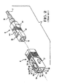
- a commercially available fibre optic plug assembly is shown generally at 2 which is insertable and latchably connected to a receptacle jack assembly shown at 4.
- This known fibre optic connector 2 is comprised of an inner plug body shown generally as 6 and an outer plug housing 8.
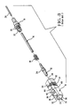
- the inner plug body 6 shown in Figure 2 is shown in Figure 3 exploded to include an insulative housing body 10, a ferrule 12, a coil spring 14, insulative tubing 16, and an inner body portion 18.
- the insulative housing body 10 includes an inner cavity 20 for receiving the ferrule 12 and a rear portion of the inner cavity 20 is profiled to receive a front end 22 of the inner body portion 18 such that the ceramic ferrule 12 is floatable within the insulative housing body 10 and spring loaded between a piston portion 24 of the ferrule assembly and an outer flange 26 of the inner body portion 18.
- an optical fibre 28 is slidably receivable through the inner body portion 18, insulative tubing 16, the coil spring 14, and into its final position within the ferrule 12, whereby the ferrule 12 and inner body portion 18 are received into the insulative housing body 10 for spring loaded retention therein.
- the housing body to includes upper and lower surfaces 30 and side surfaces 32.
- the insulative housing body 10 has chamfered surfaces as 34 providing a polarizing feature for the insulative housing body 10 as will be described in greater detail herein.
- the insulative housing body 10 has recessed surfaces at 36 which extend rearwardly to a transverse rib 38, behind which is a further recessed surface at 40. Continuing rearwardly, a ramped surface is provided at 42 which leads up to a raised stop surface 44.
- the lower side of the insulative housing body 10 as viewed in Figure 3 is identical to the top surface. However, as viewed in Figure 3, only one such surface is visible.
- the outer plug housing 8 is shown in greater detail and includes an inner cavity at 50 for slidably receiving the housing body 10, from the rear thereof, into a locked condition.
- the cavity 50 is provided with surfaces 52 which correspond to the chamfered surfaces 34 for correct polarization of the housing body 10 into the outer plug housing 8.
- the outer plug housing 8 is provided with opposite latching openings at 54 which extend toward the front mating face 56.
- the openings 54 define two side walls 58 flanking the opening 54 and which are interconnected by upper and lower bridge portions 60.
- the side walls 58 extend rearwardly from the front face 56 and include camming surfaces 62 which extend obliquely rearwardly to a top surface 64 of the outer housing 8.
- a recess is formed including a declining edge 66 and a horizontal edge 68.
- a notch is formed at 70 which forms a stop member for the housing 8, as will be described in greater detail herein.
- the housing 8 includes a polarizing lug 72 on one side only of the housing for correct polarization with the receptacle assembly 4.
- the inner plug body 6 can now be slidably received into the rear of the outer plug housing 8 to a fully locked position, as shown in Figure 1, where the raised stop surface 44 is received within the notch 70, which prevents withdrawal of the plug body 6.
- the plug body 6 is also moveable forwardly within the plug housing 8, to a position where the transverse rib 38 abuts a rear edge of the bridge portion 60.
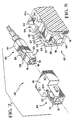
- the jack assembly 4 is comprised of two identical jack receptacle halves 80 having flanges 82 which can be butted one to the other and fixed in place by such means as adhesive or ultrasonic welding.
- the jack assembly 4 further includes two identical latch members 84 which receive between them a fibre aligning ferrule 85.
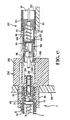
- the ferrule 85 is received within openings 86 in the rear of the latch members 84, and is retained within cylindrical sleeve portions 88 of the latch members 84 by way of a shoulder 90 at the front end of the cylindrical sleeves 88, as best shown in Figure 4 and 5.
- the latch members 84 further include latch extensions 91 which include individual latch projections 92, which are flanked by side wing portions at 94.
- a metal spring clip member 95 can be clipped to one of the receptacle halves 80, whereby the jack assembly 4 can be clipped to a panel, such as a mother board 100 as shown in Figure 5, where the jack assembly 4 is held to the mother board 100 between the flanges 82 and a locking lance found on the clip member 95.
- the identical jack receptacle halves 80 each includes a polarizing slot 98 for receiving the polarizing lug 72 on the plug assembly 2.
- the plug assembly 2 can be received within a receiving cavity 99 ( Figure 5) of the jack assembly 4 such that the ferrule 12 is positioned within the aligning ferrule 85 in the jack assembly 4.
- the wing members 94 ( Figure 4) on the latch extensions 91 are as wide as, the cam surfaces 62, ( Figure 2) but narrower than inner surfaces 71 ( Figure 1) on the side walls 58 ( Figure 2).
- the outer plug housing 8 can be moved rearwardly to the position where the front edge of the transverse rib 38 abuts the rear edge of the bridge portion 60 ( Figure 2) causing the outer wings portions 94 ( Figure 4) to ride up the surfaces 66 and be situated on the upper surface 64 ( Figure 2). This causes raising up of the latch member 92, such that further rearward movement of the outer plug housing 8 causes removal of the entire plug assembly 2.
- the invention proposes that a fibre optic plug connector assembly similar to that disclosed in Figures 1 through 3 is mounted on a daughter board along side of a receptacle connector similar to that disclosed in EP-A- 0422785. Similarly, a receptacle assembly similar to that disclosed in Figures 4 through 5 above would be interconnected to the mother board along side the tab header which is also described in the above mentioned European Patent Application. While the combination of fibre connectors and a connector system as disclosed in the above mentioned European Patent Application is highly desirable, new complications are added by their combination.
- FIG. 6 a fibre optic system useable in combination with electrical connectors, so-called hybrid connectors, is shown.
- the plug which mounts from the left hand side of the mother board can be, and in fact is shown to be, identical to the prior art plug connector of Figure 1,
- the receptacle assembly is somewhat different from that shown in Figure 1 and is therefore labeled by reference numeral 204.
- the jack receptacle half 80 and inner latch member 84 are basically the same as that described above with reference to Figures 1-5.
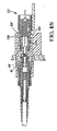
- a plug assembly having some similar features to the plug assembly 2 is generally shown at 102 with an outer housing 104 mounted to a printed circuit daughter board 101 (Fig. 6) and an inner plug body 106 that is slidably received within a cavity 111 of the outer housing 104.
- the plug body 106 has an insert housing 109 ( Figure 7) comprising an inner cavity 110 in which is mounted (Fig. 6) a coil spring 112 that pushes on a piston 114, and to the piston 114 is mounted a ferrule 116 which has a thin central bore for receiving an optical fibre.
- the insert housing 109 is shown having a shroud 118 surrounding the ferrule 116.
- the plug body 106 also has a transverse rib of a plug latching means 128 having a recess 126 therebehind.
- the plug body 106 has a resilient thrust lance 150 which, for example, could be clipped around the insert housing 109, or can be an integral part of the plug body 106.
- the outer housing 104 includes camming members 120 with a tapered front camming surface 124, an upper surface 125, a tapered rear release surface 122 and a lower surface 121. There are two camming members 120 separated by an opening 127. At a front end of the outer housing 104 is a bridge portion 131 that joins the camming members 120. The bridge 131 also serves to retain forward extraction of the plug body 106, whereby forward extraction of the plug body 106 causes the transverse rib 128 of the plug body 106 to abut the bridge 131.
- the insert housing 109 has an outer peripheral surface 151 that is substantially profiled as an inner surface 153 of the cavity 111 such that the plug body 106 is slidably held within the cavity 111.
- the resilient thrust lances 150 that project obliquely rearwardly are engageable with a shoulder 152 of the outer housing 104.
- the plug body 106 is held in an opposite sense by the transverse rib of the plug latching means 128 against the bridge portion 131.
- the thrust lances 150 enable insertion of the plug body 106 into the plug assembly 2 because resilient thrust lances 150 are engaged with the shoulder 152 of the outer housing 104 whilst spring forces on the butting ferrules 12, 116 provoke a rearwards pushing force on the plug body 106. It should be pointed out at this point that the ferrule 116 extends outwardly beyond the shroud 118 further than the corresponding ferrule 12 beyond its corresponding shroud 35, for reasons which will be apparent herein.
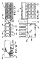
- a jack assembly 204 is shown, which is similar in nature to the jack assembly 4 as described above.
- the mother board side can have a jack receptacle half 80 similar to that described above, as well as a inner latch member 84 which is identical to that described above.
- a special jack housing part 280 is required having centrally positioned thrust disengagement means 248 in the form of ribs positioned adjacent to the mating face of the jack housing 280, such that the width of the thrust engagement means 248 are profiled to be received between the two camming members 120 ( Figure 8).
- a different latch member 284 is also required, which has jack latching arms 291 substantially longer than the corresponding latch arms 91 of the opposite side, for reasons which will be described in greater detail herein.
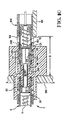
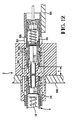
- FIG. 9 The latching sequence is best shown in Figures 9 to 13, whereby, in Figure 9, the plug assembly 102 is shown partially inserted into a cavity 213 of the jack assembly 204 with the ferrule 116 partially inserted into the aligning ferrule 85 and the jack latching arms 291 biased resiliently outwards due to engagement of the wings 294 with the camming surface 124, 125.
- the latching protrusion 292 passes over the bridge portion 131 between the camming members 120.
- Figure 10 shows the latching protrusion 292 within a recess 126 of the inner plug body 106 and behind the transverse rib 128 preventing rearward extraction thereof.
- the latching protrusions 292 project through the opening 127 between camming members 120 (also see Figure 8) and the wings 294 rest on the lower camming surfaces 121.
- the shroud 118 is over the center part 288 and the ferrules 12, 116 abut each other with a spring force.
- optical connection between the two plug assemblies 2, 102 is achieved and the plugs are releasably latched to the jack assembly 204. It is important to note that the shroud 118, unlike its counterpart 35, is spaced from the end surface 289, when in the position shown in Figure 10.
- the jack assembly 204 is provided with thrust desengagement means in the form of actuator ribs 248 that slide between the camming members 120 of the plug assembly 102, as seen in Figures 9, 10, and 11 and the ribs 248 have an inner surface 249 ( Figure 6) very close to the outer surface 151 of the plug body 106.
- Figure 11 illustrates the daughter board 101 and plug assembly 102 inserted even further into the jack assembly 204 until the thrust disengagement means 248 in form of ribs are inserted past the shoulder 152 into the rib slots 151a of the outer housing 104, the resilient thrust lances 150 being deflected inwards such that they disengage with the shoulder 152.
- Figure 11 actually represents an instantaneous view, as in this position the plug body 106 is no longer thrust forward by the resilient thrust lances 150 and would therefore spring rearwards until the latching protrusions 292 catch the transverse ribs 128, as shown in Figure 12.
- the force loop of the connection as shown in Figures 12 and 13 is contained within the connector and is as follows: plug ferrule 116-piston 114-spring 112-insert housing 109-jack latching means 291-inner plug body 6-coil spring 14-jack piston 24-ferrule 12.
- the aforementioned force loop does not load the boards, as was mentioned above, when the thrust means 150, 152 were engaged.
- the outer housing 104 and, thus, the daughter board 101 can thereafter be slid forwards with virtually no resistance to the position of Figure 13 and back again to the position of Figure 12, thereby allowing a tolerance T in the axial spacing of the daughter board 101 to the mother board 100, as represented in Figure 12
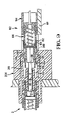
- FIG. 18 an alternative embodiment of plug connector is shown in 102' whereby the thrust lances 150' are integrally molded with the insert housing 109 and include camming surfaces 149' which cooperate with the thrust disengagement means in form of ribs 248 on the jack housing to disconnect the insert housing 109 from the outer housing 104.
- Figure 18 further shows an alternative latch arm 91' which is reversely formed and includes integral wing members 94'.
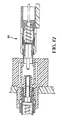
- FIG 19 a further connector assembly is shown in Figure 19 at 300 comprising an electrical connector housing portion 301 and a fibre plug portion 302 having an outer housing 304.
- Any number of a plurality of cavities can be provided at 311 which will receive the inner plug bodies 106 ( Figure 7) in an identical manner.
- Camming members 320 are provided adjacent each cavity 311 for latching interconnection with the plug body 106 as previously described.
- the housing 304 has a lower surface 330 for abutment against the daughter board and a plurality of aligning posts 332 extending therefrom for correct positioning of the housing 304 on the daughter board.
- the connector portion 301 includes a plurality of terminal inserts 340, which are similar to above mentioned European Application number (0 422 785).
- the invention described above relates to the preferred embodiment. one could imagine, however, many different shapes sizes and attachment points of the plug housing, plug latches, jack housing, jack insert, thrust means and the number and shape of the camming members, as well as the number of optical fibres mounted within the connector, without departing from the scope of this invention.
Landscapes
- Physics & Mathematics (AREA)
- General Physics & Mathematics (AREA)
- Optics & Photonics (AREA)
- Mechanical Coupling Of Light Guides (AREA)
Claims (10)
- Ensemble connecteur pour fibres optiques comprenant un ensemble jack destiné à recevoir, au niveau d'un de ses côtés, au moins une ferrule (12) de jack, et un ensemble fiche (102, 132) insérable dans l'ensemble jack depuis son côté opposé et possédant au moins une ferrule (116) de fiche, positionnable coaxialement avec ladite ferrule de jack en vue de réaliser l'interconnexion optique de fibres optiques supportées par les ferrules (12, 116), ledit ensemble fiche comprenant un logement extérieur (104), un corps de fiche intérieur (106) monté coulissant sur la (les) ferrule(s) de fiche et capable de coulisser axialement dans une cavité traversante (111) du logement extérieur, et un moyen formant ressort (112) destiné à pousser de façon élastique la (les) ferrule(s) de fiche vers la (les) ferrule(s) de jack complémentaire(s), ledit corps de fiche intérieur (106) présentant un moyen de butée extérieur (150), susceptible de fléchir radialement, destiné à prendre appui contre un épaulement (152) tourné vers l'avant du logement extérieur (104) de manière à permettre l'insertion de l'ensemble fiche dans l'ensemble jack par déplacement vers l'avant du logement extérieur dans l'ensemble jack, ledit logement extérieur (104) présentant une ouverture (127) au niveau de son extrémité avant et ledit corps de fiche intérieur (106) présentant un moyen de verrouillage de fiche extérieur (128) en regard de ladite ouverture (127), destiné à coopérer avec l'ensemble jack (204) ; et ledit ensemble jack (204) comprenant un moyen de verrouillage de jack (284) coopérant, via l'ouverture (127), avec le moyen de verrouillage de fiche, au moment où l'ensemble jack atteint une position axiale prédéterminée dans l'ensemble jack, en vue de retenir le corps de fiche intérieur dans l'ensemble jack en vue de réaliser l'interconnexion optique des fibres optiques, et un moyen de dégagement de butée (248) destiné à faire fléchir ledit moyen de butée radialement vers l'intérieur, jusqu'à une position dégagée dudit épaulement (152) lorsque ledit ensemble fiche est déplacé plus en avant, au-delà de ladite position axiale prédéterminée, en vertu de quoi le logement extérieur (104) seul peut être davantage déplacé axialement sur une distance d'absorption de tolérance (T) par rapport à l'ensemble jack (204) connecté optiquement et mécaniquement et au corps de fiche intérieur (106), ledit déplacement axial supplémentaire n'ayant aucun effet sur la force exercée par le moyen formant ressort (112), caractérisé en ce que l'ouverture (127) possède ledit épaulement (152) tourné vers l'avant au niveau de son extrémité arrière, et une partie de raccordement (131) faisant saillie dans la cavité (111) du logement extérieur (104) au niveau d'une extrémité avant de l'ouverture et destinée à coopérer avec le moyen de verrouillage de fiche (128) de manière à empêcher l'extraction vers l'avant du corps de fiche (106) par rapport à ladite cavité (111), et en ce que le moyen de butée comprend une patte de butée élastique (150) se prolongeant vers l'arrière et faisant saillie obliquement vers l'extérieur dans l'ouverture (127) du logement de fiche, et le moyen de verrouillage de jack (284) et le moyen de dégagement de butée (248) sont positionnés de telle sorte que, après être passés par-dessus la partie de raccordement (131) lors de l'insertion de l'ensemble fiche dans l'ensemble jack, ils puissent respectivement s'engager avec le moyen de verrouillage de fiche et la patte de butée (150) à travers l'ouverture (127).
- Ensemble connecteur selon la revendication 1, caractérisé en ce que l'ensemble fiche (102, 132) comprend une pluralité de ferrules (116), chacune servant à supporter une fibre, et chaque ferrule (216) est montée dans un corps de fiche (106) distinct.
- Ensemble connecteur selon la revendication 1 ou 2, caractérisé en ce que le ou chaque corps de fiche (106) présente une surface extérieure (151) proche d'une surface intérieure (153) du logement extérieur (209) de sorte que, lorsque le moyen de butée (150, 352) est dégagé, le corps de fiche (106) est guidé axialement par coulissement dans la cavité (111).
- Ensemble connecteur selon l'une quelconque des revendications 1 à 3, caractérisé en ce que la patte de butée (150) est solidaire d'un logement à insertion (109) du corps de fiche (106).
- Ensemble connecteur selon l'une quelconque des revendications 1 à 4, caractérisé en ce que le moyen de dégagement de butée (248) est placé à côté de la face avant de l'ensemble jack (204).
- Ensemble connecteur selon l'une quelconque des revendications 1 à 5, caractérisé en ce que le moyen de verrouillage de jack (284) comprend au moins un bras de verrouillage élastique (291) fixé à l'ensemble jack (204) et se prolongeant vers l'avant à partir de celui-ci jusqu'à une extrémité libre dotée d'une saillie de verrouillage (292) coopérant avec le moyen de verrouillage de fiche en forme de nervure (128) sur le corps de fiche (106) en vue de retenir celui-ci.
- Ensemble connecteur selon la revendication 6, caractérisé par au moins une paire de bras de verrouillage (291) par ferrule de fiche (116).
- Ensemble connecteur selon l'une quelconque des revendications 1 à 7, caractérisé en ce que le logement de fiche (104) possède des éléments de came (120) destinés à coopérer avec des ailes (294) fixées au moyen de verrouillage de jack (284) de l'ensemble jack (204), les éléments de came (120) possédant des surfaces de came (122, 125), en vertu de quoi les ailes (294) chevauchent ces surfaces (122, 125) de sorte que, lors du retrait de la fiche (102) par rapport à l'ensemble jack (204), les ailes (294) engagent les surfaces de came (122, 125) en provoquant la poussée élastique vers l'extérieur du moyen de verrouillage de jack (284) et donc le déverrouillage de l'ensemble jack (204) par rapport au corps de fiche (106).
- Ensemble connecteur selon la revendication 8, caractérisé en ce que la fiche (102) possède au moins une paire d'éléments de came (120) se prolongeant depuis le haut ou le bas du logement de fiche (104) et séparés par l'ouverture (127), ladite ouverture permettant au moyen de verrouillage de jack (284) de s'engager avec le moyen de verrouillage de fiche, lequel prend la forme d'une nervure (128) du corps de fiche (106), en vue de retenir la fiche (102) sur l'ensemble jack (204).
- Ensemble connecteur selon la revendication 9, caractérisé par des paires des éléments de came (120) sur le dessus et le dessous opposé, respectivement, du logement de fiche (104).
Applications Claiming Priority (3)
| Application Number | Priority Date | Filing Date | Title |
|---|---|---|---|
| GB939307488A GB9307488D0 (en) | 1993-04-08 | 1993-04-08 | Optical fibre connector latching mechanism |
| GB9307488 | 1993-04-08 | ||
| PCT/US1994/003511 WO1994024594A1 (fr) | 1993-04-08 | 1994-03-30 | Mecanisme de verrouillage pour un connecteur a fibre optique |
Publications (2)
| Publication Number | Publication Date |
|---|---|
| EP0650602A1 EP0650602A1 (fr) | 1995-05-03 |
| EP0650602B1 true EP0650602B1 (fr) | 2003-05-07 |
Family
ID=10733648
Family Applications (1)
| Application Number | Title | Priority Date | Filing Date |
|---|---|---|---|
| EP94912364A Expired - Lifetime EP0650602B1 (fr) | 1993-04-08 | 1994-03-30 | Ensemble de connexion pour fibre optique |
Country Status (14)
| Country | Link |
|---|---|
| US (2) | US5542015A (fr) |
| EP (1) | EP0650602B1 (fr) |
| JP (1) | JPH08502133A (fr) |
| KR (1) | KR100321627B1 (fr) |
| CN (1) | CN1044289C (fr) |
| BR (1) | BR9404890A (fr) |
| CA (1) | CA2133215C (fr) |
| DE (1) | DE69432625T2 (fr) |
| FI (1) | FI115002B (fr) |
| GB (1) | GB9307488D0 (fr) |
| HU (1) | HUT68028A (fr) |
| PL (1) | PL173558B1 (fr) |
| RU (1) | RU2128852C1 (fr) |
| WO (1) | WO1994024594A1 (fr) |
Cited By (1)
| Publication number | Priority date | Publication date | Assignee | Title |
|---|---|---|---|---|
| EP2293129A1 (fr) | 2009-09-03 | 2011-03-09 | Tyco Electronics Raychem BVBA | Supports de positionnement pour ensemble de connecteur optique à fibres, ensemble de connecteur optique à fibres et unité de terminaison de fibre |
Families Citing this family (210)
| Publication number | Priority date | Publication date | Assignee | Title |
|---|---|---|---|---|
| DE4437976C2 (de) * | 1994-10-25 | 1997-07-24 | Henning Faseroptik Gmbh | Kupplungsvorrichtung für Lichtwellenleiter |
| JP3212063B2 (ja) * | 1995-03-08 | 2001-09-25 | 日本電信電話株式会社 | 光レセプタクル |
| CA2199711C (fr) * | 1995-07-12 | 2003-01-07 | Ichiro Matsuura | Fiche de connecteur et connecteur pour optiques |
| TW358552U (en) * | 1995-08-02 | 1999-05-11 | Molex Inc | Adapter for interconnecting optical fiber connectors |
| US5737464A (en) * | 1995-08-31 | 1998-04-07 | Siecor Corporation | Monolithic optical fiber coupler including sleeve with flexible flap |
| DE19539549C1 (de) * | 1995-10-12 | 1996-12-05 | Siemens Ag | Optischer Steckverbinder |
| JP2000501222A (ja) * | 1995-11-06 | 2000-02-02 | ザ ウィタカー コーポレーション | 電気コネクタ用の結合構造 |
| US6045270A (en) | 1995-12-22 | 2000-04-04 | Methode Electronics, Inc. | Massive parallel optical interconnect system |
| US5835594A (en) * | 1996-02-09 | 1998-11-10 | Intel Corporation | Methods and apparatus for preventing unauthorized write access to a protected non-volatile storage |
| US5796896A (en) * | 1996-03-14 | 1998-08-18 | Minnesota Mining And Manufacturing Company | Multi-ferrule fiber optic connector for high density backplane applications |
| EP0805366A1 (fr) * | 1996-05-02 | 1997-11-05 | Harting KGaA | Connecteur |
| US5680494A (en) * | 1996-05-16 | 1997-10-21 | Bell Atlantic Network Services, Inc. | FC-type optical fiber connector adapter |
| US5708742A (en) * | 1996-06-18 | 1998-01-13 | Northern Telecom Limited | Combinations of printed circuit boards and face plates |
| AU4582197A (en) * | 1996-06-21 | 1998-01-07 | Pennoptics, Inc. | Optical fiber connector and method of connecting optical fibers |
| DE19626036A1 (de) * | 1996-06-28 | 1998-01-02 | Whitaker Corp | Optischer Steckverbinder |
| JP3066739B2 (ja) | 1996-07-15 | 2000-07-17 | セイコーインスツルメンツ株式会社 | 汎用光コネクタ及びベーシックプラグ |
| US5815617A (en) * | 1996-10-25 | 1998-09-29 | Federal Signal Corporation | Fiber optic cable connector |
| US5937121A (en) * | 1997-01-03 | 1999-08-10 | The Siemon Company | Adapters for coupling optical fiber |
| DE19807596C2 (de) * | 1997-02-22 | 1999-11-11 | Spinner Gmbh Elektrotech | LWL-Steckverbindung |
| SE516303C2 (sv) * | 1997-03-20 | 2001-12-17 | Ericsson Telefon Ab L M | Kontaktdon för minst en optofiber |
| US5867621A (en) * | 1997-04-23 | 1999-02-02 | Siecor Corporation | Adapter and guide pin assembly for coupling of fiber optic connectors |
| CA2294930A1 (fr) * | 1997-06-24 | 1998-12-30 | Siemens Electromechanical Components Gmbh & Co. Kg | Contenant a ferrules et dispositif servant a assembler des fibres optiques multiples |
| DE59713003D1 (de) * | 1997-11-13 | 2009-06-04 | Diamond Sa | Steckeranordnung für eine optische Einschub-Steckverbindung |
| US6644868B2 (en) | 1997-11-13 | 2003-11-11 | Diamond Sa | Plug construction for an optical plug-and-socket connection |
| US5915058A (en) * | 1998-01-05 | 1999-06-22 | Molex Incorporated | Fiber optic connector assembly |
| US6173099B1 (en) * | 1998-06-05 | 2001-01-09 | Stratos Lightwave, Inc. | Snap-in coupling |
| US6010250A (en) | 1998-07-09 | 2000-01-04 | Sung; Allen L. | Plug for fibre optic cable |
| DE19845854C2 (de) * | 1998-10-05 | 2000-11-02 | Framatome Connectors Int | Lichtwellenleiter-Steckverbinder für eine mechanischlösbare Verbindung zwischen-mindestens einem LWL-Steckerpaar-mindestens einem LWL-Stecker und einer Leiterplatte |
| US6116789A (en) * | 1998-11-12 | 2000-09-12 | Delphi Technologies, Inc. | Coupling assembly for coupling glass optical fiber leads to plastic optical fiber leads of a hybrid fiber optic lighting distribution system |
| US6347888B1 (en) | 1998-11-23 | 2002-02-19 | Adc Telecommunications, Inc. | Fiber optic adapter, including hybrid connector system |
| US6454464B1 (en) | 1998-12-28 | 2002-09-24 | Computer Crafts, Inc. | Fiber optic connectors and transceiver test devices |
| US6464408B1 (en) | 1998-12-28 | 2002-10-15 | Computer Crafts, Inc. | Fiber optic connectors |
| FR2789183B1 (fr) * | 1999-02-03 | 2001-04-13 | Framatome Connectors France | Systeme de connecteurs optiques a nettoyage aise |
| US6760531B1 (en) | 1999-03-01 | 2004-07-06 | Adc Telecommunications, Inc. | Optical fiber distribution frame with outside plant enclosure |
| US6431762B1 (en) * | 1999-04-09 | 2002-08-13 | Seiko Instruments Inc. | Optical connector adapter |
| DE19922250A1 (de) * | 1999-05-14 | 2000-11-16 | Delphi Tech Inc | Steckverbinder |
| US6325547B1 (en) * | 1999-10-06 | 2001-12-04 | Lucent Technologies Inc. | Optical connector having a housing assembly that is comprised of polyphenylsulfone |
| US6461053B1 (en) * | 1999-10-13 | 2002-10-08 | The Whitaker Corporation | Optical connector having multiple modular housings |
| DE19955316A1 (de) * | 1999-11-17 | 2001-05-23 | Delphi Tech Inc | Steckverbinder |
| US6361218B1 (en) * | 1999-12-07 | 2002-03-26 | Molex Incorporated | Fiber optic connector module |
| US6371657B1 (en) | 1999-12-07 | 2002-04-16 | Molex Incorporated | Alignment system for mating connectors |
| US6406192B1 (en) | 1999-12-07 | 2002-06-18 | Molex Incorporated | Connector assembly floating mount |
| US6715931B1 (en) | 1999-12-07 | 2004-04-06 | Wenzong Chen | Self-contained fiber optic connector module |
| US6331079B1 (en) | 1999-12-07 | 2001-12-18 | Molex Incorporated | Mounting system for a connector assembly to a substrate |
| JP2002214481A (ja) * | 2001-01-19 | 2002-07-31 | Hirose Electric Co Ltd | 光コネクタ |
| DE10004603A1 (de) * | 2000-02-03 | 2001-08-09 | Delphi Tech Inc | Steckverbinder |
| WO2001056855A1 (fr) * | 2000-02-07 | 2001-08-09 | Te Huruhuru Properties Ltd | Remonte-pente portatif |
| US6364536B1 (en) | 2000-03-30 | 2002-04-02 | Wenzong Chen | Floating connector assembly |
| US6530700B2 (en) * | 2000-04-21 | 2003-03-11 | Teraconnect, Inc. | Fiber optic connector |
| US6580865B1 (en) * | 2000-06-05 | 2003-06-17 | Infineon Technologies North America Corp. | Optical fiber systems |
| DE50003105D1 (de) * | 2000-06-15 | 2003-09-04 | Diamond Sa | Steckeranordnung für eine optische Einschub-Steckverbindung |
| US6695485B1 (en) * | 2000-07-28 | 2004-02-24 | Tellabs Operations, Inc. | Bezel for fiber optic components |
| US6682230B1 (en) * | 2000-08-09 | 2004-01-27 | Berg Technology, Inc. | Optical connector and printed circuit board assembly with movable connection |
| JP3769178B2 (ja) * | 2000-09-06 | 2006-04-19 | ヒロセ電機株式会社 | 光アダプタ |
| US6572273B1 (en) | 2000-11-07 | 2003-06-03 | Itt Manufacturing Enterprises, Inc. | Fiber optic connector with removable alignment sleeve |
| US6572276B1 (en) * | 2000-11-21 | 2003-06-03 | Euromicron Werkezeuge Gmbh | Plug for fiber optic cables with a plug housing |
| WO2002048763A1 (fr) | 2000-12-13 | 2002-06-20 | Teraconnect, Inc. | Systeme de mise en boitier pour reseaux optoelectroniques bidimensionnels |
| US6601998B2 (en) | 2000-12-13 | 2003-08-05 | Teraconnect, Inc | Optical waveguide assembly for interfacing a two-dimensional optoelectronic array to fiber bundles |
| GB2371374A (en) * | 2001-01-18 | 2002-07-24 | Mao-Hsiang Chen | Optical fibre plug connector with opposing holes for elastic inserts |
| JP3513114B2 (ja) * | 2001-03-02 | 2004-03-31 | ヒロセ電機株式会社 | フェルール保持構造 |
| US6944387B2 (en) * | 2001-04-30 | 2005-09-13 | Telect, Inc. | Fiber optic connector tray system |
| US6712523B2 (en) * | 2001-06-01 | 2004-03-30 | Adc Telecommunications, Inc. | Bulkhead adapter with optical fiber for signal attenuation |
| JP4053409B2 (ja) * | 2001-12-06 | 2008-02-27 | シャープ株式会社 | コネクタおよびそれを備えた電子機器 |
| US6722789B1 (en) | 2001-12-12 | 2004-04-20 | Itt Manufacturing Enterprises, Inc. | Releasable terminus retention |
| DE10219935A1 (de) * | 2002-05-03 | 2003-11-27 | Krone Gmbh | Vorrichtung für eine Glasfaserverbindung |
| JP2004029162A (ja) * | 2002-06-21 | 2004-01-29 | Sharp Corp | メカニカルロック式コネクタ |
| US7396165B2 (en) * | 2002-11-01 | 2008-07-08 | Finisar Corporation | Counterbore base member for ferrule-type optical connector |
| US6878016B2 (en) * | 2002-12-12 | 2005-04-12 | Symbol Technologies, Inc. | High cycle connector contact system |
| US6619994B1 (en) * | 2002-12-19 | 2003-09-16 | Jess-Link Products Co., Ltd. | Jack plug of digital connector |
| US20040120653A1 (en) * | 2002-12-19 | 2004-06-24 | Zen-Chyuan Chen | Optical fiber joint |
| US7142764B2 (en) | 2003-03-20 | 2006-11-28 | Tyco Electronics Corporation | Optical fiber interconnect cabinets, termination modules and fiber connectivity management for the same |
| US7198409B2 (en) | 2003-06-30 | 2007-04-03 | Adc Telecommunications, Inc. | Fiber optic connector holder and method |
| US7233731B2 (en) | 2003-07-02 | 2007-06-19 | Adc Telecommunications, Inc. | Telecommunications connection cabinet |
| JP4058394B2 (ja) * | 2003-07-10 | 2008-03-05 | シャープ株式会社 | 光コネクタのレセプタクル、光コネクタ、並びに電子機器 |
| JP3910950B2 (ja) * | 2003-09-01 | 2007-04-25 | ヒロセ電機株式会社 | 遮蔽機構を有する光コネクタ |
| US6874945B2 (en) * | 2003-09-08 | 2005-04-05 | Itt Manufacturing Enterprises, Inc. | Optic fiber connection system with terminus-holding body slidable in housing |
| US6984073B2 (en) * | 2003-10-14 | 2006-01-10 | 3M Innovative Properties Company | Optical and opto-electronic interconnect alignment system |
| DE112004002592D2 (de) * | 2003-10-28 | 2006-09-21 | Euromicron Werkzeuge Gmbh | Faseroptischer Stecker sowie Einfach- und Doppelkupplung zur Aufnahme eines derartigen Steckers |
| US7369741B2 (en) * | 2003-11-17 | 2008-05-06 | Fiber Optics Network Solutions Corp. | Storage adapter with dust cap posts |
| US6983095B2 (en) * | 2003-11-17 | 2006-01-03 | Fiber Optic Network Solutions Corporation | Systems and methods for managing optical fibers and components within an enclosure in an optical communications network |
| JP2005189332A (ja) * | 2003-12-24 | 2005-07-14 | Three M Innovative Properties Co | 光コネクタ、コネクタ付き光ファイバ、光ファイバ接続装置及び光ファイバ接続方法 |
| NL1025379C2 (nl) * | 2004-02-02 | 2005-08-03 | Framatome Connectors Int | Optisch connectorsysteem. |
| NL1025381C2 (nl) * | 2004-02-02 | 2005-08-03 | Framatome Connectors Int | Optisch connectorsysteem. |
| US7074066B2 (en) * | 2004-03-29 | 2006-07-11 | Tyco Electronics Corporation | Sealed electrical connector having internal latching mechanism therefore |
| JP3925933B2 (ja) * | 2004-04-02 | 2007-06-06 | 日本航空電子工業株式会社 | 光コネクタの分解治具 |
| US20060002660A1 (en) * | 2004-04-22 | 2006-01-05 | Martin Wisecarver | Two-piece nose assembly with solid sleeve for optical subassembly |
| US7427165B2 (en) * | 2004-06-16 | 2008-09-23 | Spectros Corporation | Optical and electrical hybrid connector |
| US7218827B2 (en) * | 2004-06-18 | 2007-05-15 | Adc Telecommunications, Inc. | Multi-position fiber optic connector holder and method |
| JP4416591B2 (ja) * | 2004-07-16 | 2010-02-17 | スリーエム イノベイティブ プロパティズ カンパニー | 光コネクタ及び光ファイバ接続システム |
| JP4544928B2 (ja) * | 2004-07-16 | 2010-09-15 | スリーエム イノベイティブ プロパティズ カンパニー | 光コネクタ及び光ファイバ接続システム |
| US7809278B2 (en) * | 2004-07-26 | 2010-10-05 | Hewlett-Packard Development Company, L.P. | Apparatus and method of providing separate control and data channels between arrays of light emitters and detectors for optical communication and alignment |
| US7623783B2 (en) * | 2004-08-10 | 2009-11-24 | Hewlett-Packard Development Company, L.P. | System and method of self-configuring optical communication channels between arrays of emitters and detectors |
| US7251388B2 (en) * | 2004-08-10 | 2007-07-31 | Hewlett-Packard Development Company, L.P. | Apparatus for providing optical communication between integrated circuits of different PC boards and an integrated circuit assembly for use therein |
| US7623793B2 (en) * | 2004-08-10 | 2009-11-24 | Hewlett-Packard Development Company, L.P. | System and method of configuring fiber optic communication channels between arrays of emitters and detectors |
| US7269321B2 (en) * | 2004-08-10 | 2007-09-11 | Hewlett-Packard Development Company, L.P. | System and method of configuring fiber optic communication channels between arrays of emitters and detectors |
| US7653108B2 (en) * | 2004-09-09 | 2010-01-26 | Hewlett-Packard Development Company, L.P. | Apparatus and method of establishing optical communication channels between a steerable array of laser emitters and an array of optical detectors |
| US7229218B2 (en) * | 2004-09-20 | 2007-06-12 | Hewlett-Packard Development Company, L.P. | Apparatus and method of providing an optical connection between PC boards for optical communication |
| US7194181B2 (en) | 2005-03-31 | 2007-03-20 | Adc Telecommunications, Inc. | Adapter block including connector storage |
| US20070036489A1 (en) * | 2005-08-15 | 2007-02-15 | Barbara Grzegorzewska | Industrial interconnect system incorporating transceiver module cage |
| US7623749B2 (en) * | 2005-08-30 | 2009-11-24 | Adc Telecommunications, Inc. | Fiber distribution hub with modular termination blocks |
| US7816602B2 (en) * | 2006-02-13 | 2010-10-19 | Adc Telecommunications, Inc. | Fiber distribution hub with outside accessible grounding terminals |
| US7720343B2 (en) | 2006-02-13 | 2010-05-18 | Adc Telecommunications, Inc. | Fiber distribution hub with swing frame and modular termination panels |
| US7760984B2 (en) | 2006-05-04 | 2010-07-20 | Adc Telecommunications, Inc. | Fiber distribution hub with swing frame and wrap-around doors |
| US7496268B2 (en) * | 2006-12-13 | 2009-02-24 | Corning Cable Systems Llc | High density fiber optic hardware |
| US7822310B2 (en) * | 2007-02-28 | 2010-10-26 | Corning Cable Systems Llc | Fiber optic splice trays |
| US7549802B2 (en) * | 2007-06-28 | 2009-06-23 | Verizon Services Corp. | Fiber optic connector |
| US8798427B2 (en) | 2007-09-05 | 2014-08-05 | Corning Cable Systems Llc | Fiber optic terminal assembly |
| US8229265B2 (en) * | 2007-11-21 | 2012-07-24 | Adc Telecommunications, Inc. | Fiber distribution hub with multiple configurations |
| US7889961B2 (en) | 2008-03-27 | 2011-02-15 | Corning Cable Systems Llc | Compact, high-density adapter module, housing assembly and frame assembly for optical fiber telecommunications |
| JP4577793B2 (ja) * | 2008-06-04 | 2010-11-10 | ヒロセ電機株式会社 | 防水コネクタ、及び、この防水コネクタを用いた防水装置 |
| EP2321681B1 (fr) | 2008-08-27 | 2015-10-28 | ADC Telecommunications, Inc. | Adaptateur pour fibre optique ayant une structure d'alignement de virole moulée en une seule pièce |
| US11294135B2 (en) | 2008-08-29 | 2022-04-05 | Corning Optical Communications LLC | High density and bandwidth fiber optic apparatuses and related equipment and methods |
| US8452148B2 (en) | 2008-08-29 | 2013-05-28 | Corning Cable Systems Llc | Independently translatable modules and fiber optic equipment trays in fiber optic equipment |
| AU2008362634A1 (en) | 2008-10-09 | 2010-04-15 | Corning Cable Systems (Shanghai) Co., Ltd | Fiber optic terminal having adapter panel supporting both input and output fibers from an optical splitter |
| US8879882B2 (en) | 2008-10-27 | 2014-11-04 | Corning Cable Systems Llc | Variably configurable and modular local convergence point |
| US8417074B2 (en) | 2008-11-21 | 2013-04-09 | Adc Telecommunications, Inc. | Fiber optic telecommunications module |
| EP2194357A1 (fr) | 2008-12-03 | 2010-06-09 | Leica Geosystems AG | Elément de capteur optique pour une machine de mesure et élément de couplage du côté de la machine de mesure correspondant |
| EP2221932B1 (fr) | 2009-02-24 | 2011-11-16 | CCS Technology Inc. | Dispositif de maintien pour câble ou ensemble à utiliser avec un câble |
| JP4743724B2 (ja) * | 2009-02-26 | 2011-08-10 | ヒロセ電機株式会社 | 防水コネクタ、及び、この防水コネクタを用いた防水装置 |
| EP2237091A1 (fr) | 2009-03-31 | 2010-10-06 | Corning Cable Systems LLC | Terminal à fibres optiques pouvant être assemblé de manière amovible |
| US8699838B2 (en) | 2009-05-14 | 2014-04-15 | Ccs Technology, Inc. | Fiber optic furcation module |
| US8538226B2 (en) | 2009-05-21 | 2013-09-17 | Corning Cable Systems Llc | Fiber optic equipment guides and rails configured with stopping position(s), and related equipment and methods |
| US9075216B2 (en) | 2009-05-21 | 2015-07-07 | Corning Cable Systems Llc | Fiber optic housings configured to accommodate fiber optic modules/cassettes and fiber optic panels, and related components and methods |
| EP2443498B1 (fr) | 2009-06-19 | 2020-06-24 | Corning Optical Communications LLC | Appareil à densité élevée de compactage de câbles à fibres optiques |
| US8712206B2 (en) | 2009-06-19 | 2014-04-29 | Corning Cable Systems Llc | High-density fiber optic modules and module housings and related equipment |
| WO2010148336A1 (fr) | 2009-06-19 | 2010-12-23 | Corning Cable Systems Llc | Appareils à fibres optiques à large bande et à densité élevée et équipement et procédés associés |
| US8467651B2 (en) | 2009-09-30 | 2013-06-18 | Ccs Technology Inc. | Fiber optic terminals configured to dispose a fiber optic connection panel(s) within an optical fiber perimeter and related methods |
| PL217893B1 (pl) | 2009-10-10 | 2014-08-29 | Inst Wysokich Ciśnień Polskiej Akademii Nauk | Sposób i urządzenie do wprowadzania do jednego światłowodu światła laserowego pochodzącego z co najmniej dwóch źródeł laserowych |
| JP5182893B2 (ja) * | 2009-11-17 | 2013-04-17 | Nttエレクトロニクス株式会社 | 光コネクタプラグ |
| US8625950B2 (en) | 2009-12-18 | 2014-01-07 | Corning Cable Systems Llc | Rotary locking apparatus for fiber optic equipment trays and related methods |
| EP2354824A1 (fr) * | 2010-01-29 | 2011-08-10 | CCS Technology Inc. | Connecteur hybride |
| US8593828B2 (en) | 2010-02-04 | 2013-11-26 | Corning Cable Systems Llc | Communications equipment housings, assemblies, and related alignment features and methods |
| JP5080600B2 (ja) | 2010-02-26 | 2012-11-21 | 日本航空電子工業株式会社 | 光コネクタ内蔵プラグ |
| CN102870021B (zh) | 2010-03-02 | 2015-03-11 | 蒂安电子服务有限责任公司 | 光纤通信模块 |
| WO2011112764A1 (fr) | 2010-03-10 | 2011-09-15 | Corning Cable Systems Llc | Système torsadé de fibre optique permettant une épissure unique et de masse |
| US9547144B2 (en) | 2010-03-16 | 2017-01-17 | Corning Optical Communications LLC | Fiber optic distribution network for multiple dwelling units |
| CN102792202A (zh) * | 2010-03-19 | 2012-11-21 | 康宁公司 | 具有可平移套管的光纤接口装置 |
| US8913866B2 (en) | 2010-03-26 | 2014-12-16 | Corning Cable Systems Llc | Movable adapter panel |
| US8792767B2 (en) | 2010-04-16 | 2014-07-29 | Ccs Technology, Inc. | Distribution device |
| EP2558895B1 (fr) | 2010-04-16 | 2019-04-17 | Corning Optical Communications LLC | Dispositif d'étanchéité et de bridage pour câbles de données |
| EP2381284B1 (fr) | 2010-04-23 | 2014-12-31 | CCS Technology Inc. | Dispositif de distribution à fibre optique encastré dans le sol |
| US8705926B2 (en) | 2010-04-30 | 2014-04-22 | Corning Optical Communications LLC | Fiber optic housings having a removable top, and related components and methods |
| US9075217B2 (en) | 2010-04-30 | 2015-07-07 | Corning Cable Systems Llc | Apparatuses and related components and methods for expanding capacity of fiber optic housings |
| US9720195B2 (en) | 2010-04-30 | 2017-08-01 | Corning Optical Communications LLC | Apparatuses and related components and methods for attachment and release of fiber optic housings to and from an equipment rack |
| US8660397B2 (en) | 2010-04-30 | 2014-02-25 | Corning Cable Systems Llc | Multi-layer module |
| US8879881B2 (en) | 2010-04-30 | 2014-11-04 | Corning Cable Systems Llc | Rotatable routing guide and assembly |
| US9632270B2 (en) | 2010-04-30 | 2017-04-25 | Corning Optical Communications LLC | Fiber optic housings configured for tool-less assembly, and related components and methods |
| US9519118B2 (en) | 2010-04-30 | 2016-12-13 | Corning Optical Communications LLC | Removable fiber management sections for fiber optic housings, and related components and methods |
| US8718436B2 (en) | 2010-08-30 | 2014-05-06 | Corning Cable Systems Llc | Methods, apparatuses for providing secure fiber optic connections |
| JP5439319B2 (ja) * | 2010-09-06 | 2014-03-12 | 株式会社フジクラ | 光コネクタおよび光コネクタの挿抜方法 |
| US9547145B2 (en) | 2010-10-19 | 2017-01-17 | Corning Optical Communications LLC | Local convergence point for multiple dwelling unit fiber optic distribution network |
| CN102455468B (zh) * | 2010-10-19 | 2015-02-25 | 富士康(昆山)电脑接插件有限公司 | 光纤连接器及其组件 |
| US9279951B2 (en) | 2010-10-27 | 2016-03-08 | Corning Cable Systems Llc | Fiber optic module for limited space applications having a partially sealed module sub-assembly |
| US8662760B2 (en) | 2010-10-29 | 2014-03-04 | Corning Cable Systems Llc | Fiber optic connector employing optical fiber guide member |
| AU2011336747A1 (en) | 2010-11-30 | 2013-06-20 | Corning Cable Systems Llc | Fiber device holder and strain relief device |
| CN103403594B (zh) | 2011-02-02 | 2016-11-23 | 康宁光缆系统有限责任公司 | 适用于为设备机架中的光学底板建立光学连接的稠密的光阀遮蔽的光纤连接器及总成 |
| US9052468B2 (en) | 2011-03-04 | 2015-06-09 | Corning Cable Systems Llc | Fiber optic adapter mount |
| JP2012220797A (ja) * | 2011-04-11 | 2012-11-12 | Furukawa Electric Co Ltd:The | 光コネクタの接続構造 |
| DE112012001644T5 (de) * | 2011-04-11 | 2014-01-09 | Autonetworks Technologies, Ltd. | Optischer Verbinder und Ferrule |
| US9008485B2 (en) | 2011-05-09 | 2015-04-14 | Corning Cable Systems Llc | Attachment mechanisms employed to attach a rear housing section to a fiber optic housing, and related assemblies and methods |
| US9188747B2 (en) | 2011-05-23 | 2015-11-17 | Senko Advanced Components, Inc. | True one piece housing fiber optic adapter |
| US8989547B2 (en) | 2011-06-30 | 2015-03-24 | Corning Cable Systems Llc | Fiber optic equipment assemblies employing non-U-width-sized housings and related methods |
| US9110266B2 (en) | 2011-07-29 | 2015-08-18 | Corning Cable Systems Llc | Fiber optic cables seal and/or strain relief members, and related assemblies and methods |
| US8953924B2 (en) | 2011-09-02 | 2015-02-10 | Corning Cable Systems Llc | Removable strain relief brackets for securing fiber optic cables and/or optical fibers to fiber optic equipment, and related assemblies and methods |
| US9417418B2 (en) | 2011-09-12 | 2016-08-16 | Commscope Technologies Llc | Flexible lensed optical interconnect device for signal distribution |
| EP2764390B1 (fr) | 2011-10-07 | 2020-12-02 | CommScope Technologies LLC | Cassette de fibres optiques, système et procédé |
| US9038832B2 (en) | 2011-11-30 | 2015-05-26 | Corning Cable Systems Llc | Adapter panel support assembly |
| US9219546B2 (en) | 2011-12-12 | 2015-12-22 | Corning Optical Communications LLC | Extremely high frequency (EHF) distributed antenna systems, and related components and methods |
| US8842962B2 (en) | 2012-01-27 | 2014-09-23 | Corning Cable Systems Llc | Fiber optic cable strain relief device and method |
| US10110307B2 (en) | 2012-03-02 | 2018-10-23 | Corning Optical Communications LLC | Optical network units (ONUs) for high bandwidth connectivity, and related components and methods |
| US9004778B2 (en) | 2012-06-29 | 2015-04-14 | Corning Cable Systems Llc | Indexable optical fiber connectors and optical fiber connector arrays |
| US9250409B2 (en) | 2012-07-02 | 2016-02-02 | Corning Cable Systems Llc | Fiber-optic-module trays and drawers for fiber-optic equipment |
| JP6077797B2 (ja) * | 2012-08-30 | 2017-02-08 | 矢崎総業株式会社 | 光コネクタ |
| US9081152B2 (en) | 2012-08-30 | 2015-07-14 | Adc Telecommunications, Inc. | Adapter pack with removable sleeves |
| US9049500B2 (en) | 2012-08-31 | 2015-06-02 | Corning Cable Systems Llc | Fiber optic terminals, systems, and methods for network service management |
| US9042702B2 (en) | 2012-09-18 | 2015-05-26 | Corning Cable Systems Llc | Platforms and systems for fiber optic cable attachment |
| US9146362B2 (en) | 2012-09-21 | 2015-09-29 | Adc Telecommunications, Inc. | Insertion and removal tool for a fiber optic ferrule alignment sleeve |
| CN104838301B (zh) | 2012-09-28 | 2017-06-09 | 泰科电子英国有限公司 | 光纤盒 |
| US9146374B2 (en) | 2012-09-28 | 2015-09-29 | Adc Telecommunications, Inc. | Rapid deployment packaging for optical fiber |
| US9223094B2 (en) | 2012-10-05 | 2015-12-29 | Tyco Electronics Nederland Bv | Flexible optical circuit, cassettes, and methods |
| US8909019B2 (en) | 2012-10-11 | 2014-12-09 | Ccs Technology, Inc. | System comprising a plurality of distribution devices and distribution device |
| US9523829B2 (en) | 2012-10-18 | 2016-12-20 | Corning Optical Communications LLC | Fiber optic cable sub-assemblies with strain-relief to a circuit board and methods of assembling |
| ES2551077T3 (es) | 2012-10-26 | 2015-11-16 | Ccs Technology, Inc. | Unidad de gestión de fibra óptica y dispositivo de distribución de fibra óptica |
| ES2606755T3 (es) | 2012-10-26 | 2017-03-27 | Ccs Technology, Inc. | Dispositivo de alivio de tensión para cables y dispositivo de distribución de fibras ópticas |
| US8985862B2 (en) | 2013-02-28 | 2015-03-24 | Corning Cable Systems Llc | High-density multi-fiber adapter housings |
| US9435975B2 (en) | 2013-03-15 | 2016-09-06 | Commscope Technologies Llc | Modular high density telecommunications frame and chassis system |
| US9360649B2 (en) | 2013-05-22 | 2016-06-07 | Senko Advanced Components, Inc. | Cable guide for fiber optic cables |
| CA2916720A1 (fr) * | 2013-07-16 | 2015-04-02 | 3M Innovative Properties Company | Connecteur pour coffrets de telecommunications |
| US9488793B2 (en) | 2013-09-10 | 2016-11-08 | Corning Optical Communications LLC | Combined optical fiber and power cable |
| US9798092B2 (en) | 2013-09-30 | 2017-10-24 | Hewlett Packard Enterprise Development Lp | Optical blind-mate connector and adapter |
| JP6425003B2 (ja) * | 2014-01-17 | 2018-11-21 | 矢崎総業株式会社 | 光コネクタおよび光コネクタの嵌合構造 |
| EP3100090A4 (fr) | 2014-01-28 | 2017-09-06 | ADC Telecommunications Inc. | Module de connexion de fibres optiques coulissant avec gestion de mou de câble |
| DE102014102733B4 (de) * | 2014-02-28 | 2015-12-17 | Phoenix Contact Gmbh & Co. Kg | Steckbare Gerätekombination |
| US9494758B2 (en) | 2014-04-03 | 2016-11-15 | Commscope Technologies Llc | Fiber optic distribution system |
| US9274287B2 (en) * | 2014-05-13 | 2016-03-01 | Senko Advanced Components, Inc. | Optical fiber connector and ferrule |
| US9874702B2 (en) * | 2014-10-29 | 2018-01-23 | Hewlett Packard Enterprise Development Lp | Optical connector assembly apparatus |
| US9678287B2 (en) * | 2015-03-09 | 2017-06-13 | Cotsworks, Llc | Overboot assembly having unlatching and strain relief features for fiber optic cable terminus |
| AU2016263337A1 (en) | 2015-05-15 | 2018-01-04 | Adc Telecommunications (Shanghai) Distribution Co., Ltd. | Alignment sleeve assembly and optical fibre adapter |
| CN111061020B (zh) * | 2015-06-15 | 2022-05-24 | 日本电气株式会社 | 可插拔光学模块和光学通信系统 |
| JP6627873B2 (ja) * | 2015-06-15 | 2020-01-08 | 日本電気株式会社 | プラガブル光モジュール及び光通信システム |
| CN104991312B (zh) * | 2015-06-24 | 2017-01-11 | 中航光电科技股份有限公司 | 光缆连接器 |
| US9645323B2 (en) * | 2015-08-27 | 2017-05-09 | Senko Advanced Components, Inc. | Micro hybrid LC duplex adapter |
| EP3427096B1 (fr) | 2016-03-10 | 2023-11-15 | Corning Optical Communications LLC | Connecteurs de fibres optiques à ferrule avec équilibrage de rétraction de ferrule |
| US10295771B2 (en) | 2016-05-03 | 2019-05-21 | Corning Optical Communications LLC | Telecommunications terminal with removable modules |
| US10228521B2 (en) * | 2016-12-05 | 2019-03-12 | Senko Advanced Components, Inc. | Narrow width adapters and connectors with modular latching arm |
| CN106646766A (zh) * | 2017-03-01 | 2017-05-10 | 桥运精密部件(苏州)有限公司 | 新型组合式不锈钢尾柄插芯 |
| CN111164479B (zh) | 2017-10-02 | 2021-11-19 | 康普技术有限责任公司 | 光纤光学电路和制备方法 |
| CN109511046B (zh) * | 2019-01-14 | 2020-12-18 | 安徽松之梦科技有限公司 | 一种耳机 |
| TWM590824U (zh) * | 2019-06-05 | 2020-02-11 | 光紅建聖股份有限公司 | 具有指示燈之框架機構 |
| US11199669B1 (en) * | 2020-09-24 | 2021-12-14 | Hewlett Packard Enterprise Development Lp | Modular faceplate optical sub-assembly |
Family Cites Families (12)
| Publication number | Priority date | Publication date | Assignee | Title |
|---|---|---|---|---|
| US4406514A (en) * | 1980-03-26 | 1983-09-27 | Harris Corporation | Single fiber connector for pluggable card or module optical interconnections |
| US4852963A (en) * | 1987-06-30 | 1989-08-01 | American Telephone And Telegraph Company, At&T Bell Laboratories | Optical fiber biconic connector |
| US4872736A (en) * | 1988-04-19 | 1989-10-10 | American Telephone And Telegraph Company, At&T Bell Laboratories | Connector assembly having a latching mechanism |
| US4953941A (en) * | 1988-11-21 | 1990-09-04 | Seikoh Giken Co., Ltd. | Optical fiber connecting device |
| US5121454A (en) * | 1989-11-24 | 1992-06-09 | Nippon Telegraph And Telephone Corporation | Optical connector |
| US5129023A (en) * | 1991-05-14 | 1992-07-07 | At&T Bell Laboratories | Optical fiber connector having enhanced provisions for interconnection and for prevention of optical and mechanical disconnection |
| US5134679A (en) * | 1991-05-20 | 1992-07-28 | At&T Bell Laboratories | Connector for coupling an optical fiber on a backplane to a component on a circuit board |
| JP2538394Y2 (ja) * | 1991-05-29 | 1997-06-11 | 住友電気工業株式会社 | 光コネクタ |
| US5187768A (en) * | 1991-12-19 | 1993-02-16 | Porta Systems Corp. | Fiber optic variable signal attenuator |
| US5285510A (en) * | 1992-12-15 | 1994-02-08 | The Whitaker Corporation | Fiber optic connector |
| US5428703A (en) * | 1994-02-18 | 1995-06-27 | Augat Inc. | One-piece SC fiber optic connector |
| US5432879A (en) * | 1994-05-09 | 1995-07-11 | Augat Inc. | Nondisconnectable FC/PC fiber optic connector assembly |
-
1993
- 1993-04-08 GB GB939307488A patent/GB9307488D0/en active Pending
-
1994
- 1994-03-30 RU RU94046288A patent/RU2128852C1/ru active
- 1994-03-30 HU HU9402894A patent/HUT68028A/hu unknown
- 1994-03-30 KR KR1019940704437A patent/KR100321627B1/ko not_active IP Right Cessation
- 1994-03-30 DE DE69432625T patent/DE69432625T2/de not_active Expired - Lifetime
- 1994-03-30 BR BR9404890A patent/BR9404890A/pt not_active IP Right Cessation
- 1994-03-30 EP EP94912364A patent/EP0650602B1/fr not_active Expired - Lifetime
- 1994-03-30 WO PCT/US1994/003511 patent/WO1994024594A1/fr active IP Right Grant
- 1994-03-30 PL PL94306206A patent/PL173558B1/pl unknown
- 1994-03-30 CA CA002133215A patent/CA2133215C/fr not_active Expired - Lifetime
- 1994-03-30 JP JP6523233A patent/JPH08502133A/ja active Pending
- 1994-04-07 CN CN94104597A patent/CN1044289C/zh not_active Expired - Lifetime
- 1994-11-25 US US08/345,063 patent/US5542015A/en not_active Expired - Lifetime
- 1994-12-07 FI FI945741A patent/FI115002B/fi not_active IP Right Cessation
-
1996
- 1996-06-25 US US08/671,023 patent/US5764834A/en not_active Expired - Lifetime
Cited By (3)
| Publication number | Priority date | Publication date | Assignee | Title |
|---|---|---|---|---|
| EP2293129A1 (fr) | 2009-09-03 | 2011-03-09 | Tyco Electronics Raychem BVBA | Supports de positionnement pour ensemble de connecteur optique à fibres, ensemble de connecteur optique à fibres et unité de terminaison de fibre |
| WO2011026894A1 (fr) | 2009-09-03 | 2011-03-10 | Tyco Electronics Raychem Bvba | Moyens de positionnement pour un ensemble connecteur de fibres optiques, ensemble connecteur de fibres optiques et module de terminaison à fibres optiques |
| US10007070B2 (en) | 2009-09-03 | 2018-06-26 | CommScope Connectivity Belgium BVBA | Positioning means for a fibre optic connector assembly, a fibre optic connector assembly and fibre termination unit |
Also Published As
| Publication number | Publication date |
|---|---|
| KR100321627B1 (ko) | 2002-06-27 |
| CA2133215A1 (fr) | 1994-10-27 |
| KR950702038A (ko) | 1995-05-17 |
| GB9307488D0 (en) | 1993-06-02 |
| HU9402894D0 (en) | 1995-02-28 |
| FI115002B (fi) | 2005-02-15 |
| HUT68028A (en) | 1995-05-29 |
| US5764834A (en) | 1998-06-09 |
| PL306206A1 (en) | 1995-03-06 |
| US5542015A (en) | 1996-07-30 |
| CA2133215C (fr) | 2002-01-29 |
| FI945741A0 (fi) | 1994-12-07 |
| RU2128852C1 (ru) | 1999-04-10 |
| FI945741A (fi) | 1994-12-07 |
| RU94046288A (ru) | 1996-10-10 |
| EP0650602A1 (fr) | 1995-05-03 |
| PL173558B1 (pl) | 1998-03-31 |
| BR9404890A (pt) | 1999-06-15 |
| CN1098507A (zh) | 1995-02-08 |
| JPH08502133A (ja) | 1996-03-05 |
| WO1994024594A1 (fr) | 1994-10-27 |
| DE69432625T2 (de) | 2004-03-25 |
| DE69432625D1 (de) | 2003-06-12 |
| CN1044289C (zh) | 1999-07-21 |
Similar Documents
| Publication | Publication Date | Title |
|---|---|---|
| EP0650602B1 (fr) | Ensemble de connexion pour fibre optique | |
| US5404416A (en) | Optical connector plug | |
| US5151961A (en) | Ferrule alignment assembly for blind mating optical fiber connector | |
| JP2771870B2 (ja) | 光コネクタ | |
| EP0997753B1 (fr) | Assemblage à connecteur fibre optique | |
| EP0119013B1 (fr) | Connecteur comprenant un mécanisme pour coupler et découpler une pluralité de blocs | |
| EP0338727B1 (fr) | Assemblage de connecteur avec un mécanisme de verrouillage | |
| US6318903B1 (en) | Optical fiber connector for backplane | |
| EP0803750A1 (fr) | Connecteur à fibre optique avec embout immobile | |
| US10305222B2 (en) | Connector assembly | |
| KR20010095062A (ko) | 유동 커넥터 조립체 | |
| US5054879A (en) | Push/pull fiber optic connector | |
| US10598870B2 (en) | Fiber optic connector with dual multi-fiber ferrules, and cable assemblies and systems including the same | |
| US5960138A (en) | Backplane connector | |
| US11934020B2 (en) | Optoelectronic connections to printed circuit boards | |
| JP2002098860A (ja) | 光コネクタ用の整列装置 | |
| EP3677939B1 (fr) | Connecteur optique et procédé de connexion de connecteur optique | |
| EP0015657A2 (fr) | Connecteur de fibre optique | |
| US11320600B2 (en) | Fiber optic connector for hardware interiors and method of using same | |
| CN220626715U (zh) | 一种光纤连接头、光纤连接插头及光纤连接组件 | |
| US20230142093A1 (en) | Fiber optic adapters for use with fiber optic connectors and methods for coupling fiber optic connectors | |
| CN219552704U (zh) | 一种小型化连接器 | |
| CA2354174C (fr) | Connecteur optique | |
| NO317436B1 (no) | Lasemekanisme for en optisk fiberkontakt |
Legal Events
| Date | Code | Title | Description |
|---|---|---|---|
| PUAI | Public reference made under article 153(3) epc to a published international application that has entered the european phase |
Free format text: ORIGINAL CODE: 0009012 |
|
| 17P | Request for examination filed |
Effective date: 19941213 |
|
| AK | Designated contracting states |
Kind code of ref document: A1 Designated state(s): AT BE CH DE DK ES FR GB GR IE IT LI NL PT SE |
|
| 17Q | First examination report despatched |
Effective date: 19970108 |
|
| RIC1 | Information provided on ipc code assigned before grant |
Free format text: 7G 02B 6/38 A |
|
| RTI1 | Title (correction) |
Free format text: OPTICAL FIBRE CONNECTOR ASSEMBLY |
|
| GRAG | Despatch of communication of intention to grant |
Free format text: ORIGINAL CODE: EPIDOS AGRA |
|
| GRAG | Despatch of communication of intention to grant |
Free format text: ORIGINAL CODE: EPIDOS AGRA |
|
| GRAG | Despatch of communication of intention to grant |
Free format text: ORIGINAL CODE: EPIDOS AGRA |
|
| GRAH | Despatch of communication of intention to grant a patent |
Free format text: ORIGINAL CODE: EPIDOS IGRA |
|
| GRAH | Despatch of communication of intention to grant a patent |
Free format text: ORIGINAL CODE: EPIDOS IGRA |
|
| RBV | Designated contracting states (corrected) |
Designated state(s): DE FR GB IT |
|
| GRAA | (expected) grant |
Free format text: ORIGINAL CODE: 0009210 |
|
| AK | Designated contracting states |
Designated state(s): DE FR GB IT |
|
| REG | Reference to a national code |
Ref country code: GB Ref legal event code: FG4D |
|
| REG | Reference to a national code |
Ref country code: IE Ref legal event code: FG4D |
|
| REF | Corresponds to: |
Ref document number: 69432625 Country of ref document: DE Date of ref document: 20030612 Kind code of ref document: P |
|
| ET | Fr: translation filed | ||
| PLBE | No opposition filed within time limit |
Free format text: ORIGINAL CODE: 0009261 |
|
| STAA | Information on the status of an ep patent application or granted ep patent |
Free format text: STATUS: NO OPPOSITION FILED WITHIN TIME LIMIT |
|
| 26N | No opposition filed |
Effective date: 20040210 |
|
| REG | Reference to a national code |
Ref country code: IE Ref legal event code: MM4A |
|
| PGFP | Annual fee paid to national office [announced via postgrant information from national office to epo] |
Ref country code: IT Payment date: 20120327 Year of fee payment: 19 |
|
| PGFP | Annual fee paid to national office [announced via postgrant information from national office to epo] |
Ref country code: DE Payment date: 20130327 Year of fee payment: 20 Ref country code: FR Payment date: 20130405 Year of fee payment: 20 Ref country code: GB Payment date: 20130327 Year of fee payment: 20 |
|
| REG | Reference to a national code |
Ref country code: DE Ref legal event code: R071 Ref document number: 69432625 Country of ref document: DE |
|
| REG | Reference to a national code |
Ref country code: DE Ref legal event code: R071 Ref document number: 69432625 Country of ref document: DE |
|
| REG | Reference to a national code |
Ref country code: GB Ref legal event code: PE20 Expiry date: 20140329 |
|
| PG25 | Lapsed in a contracting state [announced via postgrant information from national office to epo] |
Ref country code: GB Free format text: LAPSE BECAUSE OF EXPIRATION OF PROTECTION Effective date: 20140329 |
|
| PG25 | Lapsed in a contracting state [announced via postgrant information from national office to epo] |
Ref country code: DE Free format text: LAPSE BECAUSE OF EXPIRATION OF PROTECTION Effective date: 20140401 |