EP0650405B1 - Tragbare, ausfahrbare und zusammenschiebbare bewegungsvorrichtung - Google Patents
Tragbare, ausfahrbare und zusammenschiebbare bewegungsvorrichtung Download PDFInfo
- Publication number
- EP0650405B1 EP0650405B1 EP93917084A EP93917084A EP0650405B1 EP 0650405 B1 EP0650405 B1 EP 0650405B1 EP 93917084 A EP93917084 A EP 93917084A EP 93917084 A EP93917084 A EP 93917084A EP 0650405 B1 EP0650405 B1 EP 0650405B1
- Authority
- EP
- European Patent Office
- Prior art keywords
- flexible connector
- location
- attached
- members
- flexible
- Prior art date
- Legal status (The legal status is an assumption and is not a legal conclusion. Google has not performed a legal analysis and makes no representation as to the accuracy of the status listed.)
- Expired - Lifetime
Links
Images


Classifications
-
- B—PERFORMING OPERATIONS; TRANSPORTING
- B05—SPRAYING OR ATOMISING IN GENERAL; APPLYING FLUENT MATERIALS TO SURFACES, IN GENERAL
- B05C—APPARATUS FOR APPLYING FLUENT MATERIALS TO SURFACES, IN GENERAL
- B05C17/00—Hand tools or apparatus using hand held tools, for applying liquids or other fluent materials to, for spreading applied liquids or other fluent materials on, or for partially removing applied liquids or other fluent materials from, surfaces
- B05C17/02—Rollers ; Hand tools comprising coating rollers or coating endless belts
- B05C17/0205—Rollers ; Hand tools comprising coating rollers or coating endless belts characterised by the handle, e.g. handle shape or material
-
- B—PERFORMING OPERATIONS; TRANSPORTING
- B05—SPRAYING OR ATOMISING IN GENERAL; APPLYING FLUENT MATERIALS TO SURFACES, IN GENERAL
- B05B—SPRAYING APPARATUS; ATOMISING APPARATUS; NOZZLES
- B05B15/00—Details of spraying plant or spraying apparatus not otherwise provided for; Accessories
- B05B15/60—Arrangements for mounting, supporting or holding spraying apparatus
- B05B15/62—Arrangements for supporting spraying apparatus, e.g. suction cups
- B05B15/628—Arrangements for supporting spraying apparatus, e.g. suction cups of variable length
-
- B—PERFORMING OPERATIONS; TRANSPORTING
- B25—HAND TOOLS; PORTABLE POWER-DRIVEN TOOLS; MANIPULATORS
- B25G—HANDLES FOR HAND IMPLEMENTS
- B25G1/00—Handle constructions
- B25G1/04—Handle constructions telescopic; extensible; sectional
-
- B—PERFORMING OPERATIONS; TRANSPORTING
- B25—HAND TOOLS; PORTABLE POWER-DRIVEN TOOLS; MANIPULATORS
- B25J—MANIPULATORS; CHAMBERS PROVIDED WITH MANIPULATION DEVICES
- B25J1/00—Manipulators positioned in space by hand
- B25J1/04—Manipulators positioned in space by hand rigid, e.g. shelf-reachers
-
- F—MECHANICAL ENGINEERING; LIGHTING; HEATING; WEAPONS; BLASTING
- F16—ENGINEERING ELEMENTS AND UNITS; GENERAL MEASURES FOR PRODUCING AND MAINTAINING EFFECTIVE FUNCTIONING OF MACHINES OR INSTALLATIONS; THERMAL INSULATION IN GENERAL
- F16M—FRAMES, CASINGS OR BEDS OF ENGINES, MACHINES OR APPARATUS, NOT SPECIFIC TO ENGINES, MACHINES OR APPARATUS PROVIDED FOR ELSEWHERE; STANDS; SUPPORTS
- F16M11/00—Stands or trestles as supports for apparatus or articles placed thereon ; Stands for scientific apparatus such as gravitational force meters
- F16M11/02—Heads
- F16M11/18—Heads with mechanism for moving the apparatus relatively to the stand
-
- F—MECHANICAL ENGINEERING; LIGHTING; HEATING; WEAPONS; BLASTING
- F16—ENGINEERING ELEMENTS AND UNITS; GENERAL MEASURES FOR PRODUCING AND MAINTAINING EFFECTIVE FUNCTIONING OF MACHINES OR INSTALLATIONS; THERMAL INSULATION IN GENERAL
- F16M—FRAMES, CASINGS OR BEDS OF ENGINES, MACHINES OR APPARATUS, NOT SPECIFIC TO ENGINES, MACHINES OR APPARATUS PROVIDED FOR ELSEWHERE; STANDS; SUPPORTS
- F16M11/00—Stands or trestles as supports for apparatus or articles placed thereon ; Stands for scientific apparatus such as gravitational force meters
- F16M11/20—Undercarriages with or without wheels
- F16M11/24—Undercarriages with or without wheels changeable in height or length of legs, also for transport only, e.g. by means of tubes screwed into each other
- F16M11/26—Undercarriages with or without wheels changeable in height or length of legs, also for transport only, e.g. by means of tubes screwed into each other by telescoping, with or without folding
- F16M11/28—Undercarriages for supports with one single telescoping pillar
-
- F—MECHANICAL ENGINEERING; LIGHTING; HEATING; WEAPONS; BLASTING
- F16—ENGINEERING ELEMENTS AND UNITS; GENERAL MEASURES FOR PRODUCING AND MAINTAINING EFFECTIVE FUNCTIONING OF MACHINES OR INSTALLATIONS; THERMAL INSULATION IN GENERAL
- F16M—FRAMES, CASINGS OR BEDS OF ENGINES, MACHINES OR APPARATUS, NOT SPECIFIC TO ENGINES, MACHINES OR APPARATUS PROVIDED FOR ELSEWHERE; STANDS; SUPPORTS
- F16M11/00—Stands or trestles as supports for apparatus or articles placed thereon ; Stands for scientific apparatus such as gravitational force meters
- F16M11/20—Undercarriages with or without wheels
- F16M11/24—Undercarriages with or without wheels changeable in height or length of legs, also for transport only, e.g. by means of tubes screwed into each other
- F16M11/26—Undercarriages with or without wheels changeable in height or length of legs, also for transport only, e.g. by means of tubes screwed into each other by telescoping, with or without folding
- F16M11/32—Undercarriages for supports with three or more telescoping legs
-
- F—MECHANICAL ENGINEERING; LIGHTING; HEATING; WEAPONS; BLASTING
- F41—WEAPONS
- F41B—WEAPONS FOR PROJECTING MISSILES WITHOUT USE OF EXPLOSIVE OR COMBUSTIBLE PROPELLANT CHARGE; WEAPONS NOT OTHERWISE PROVIDED FOR
- F41B15/00—Weapons not otherwise provided for, e.g. nunchakus, throwing knives
- F41B15/02—Batons; Truncheons; Sticks; Shillelaghs
- F41B15/04—Batons; Truncheons; Sticks; Shillelaghs with electric stunning-means
Definitions
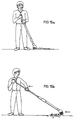
- While a pole as described is useful in certain application, it is not free from shortcomings. Primarily, it is known that, unlike the case of replacing a light bulb described above, in many operations the location at which the operation is to take place is not at a fixed distance from the user but varies either discretely or continually during the operation.
- an extendible-retractable device comprising: (a) a first member formed with a longitudinal slot and having a second rack; (b) a second member movable relative to the first member and having a first pinion near its anterior end and a second pinion near its posterior end, the second pinion engaged to the second rack; (c) a rigid connector attached to a posterior portion of the second member, the rigid connector being slidable through the longitudinal slot of the first member so that the second member is moved whenever the rigid connector is moved; (d) a third member movable relative to the first member and the second member, the third member having a first rack engaged to the first pinion, the pinion being rotatable by a cable which is attached to the first member so that anteriorly-directed motion of the second member results is anteriorly-directed motion of the third member, the third member being attached to a second pinion cable for rotating the second pinion, so that posteriorly-directed motion of the second member results is posteriorly-directed motion of
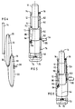
- first flexible connector 16 may be made to pass through a first hole 20 ( Figure 2), preferably located near the anterior edge 18 of first member 10 , which may, itself include a friction-reducing pulley. In either case, first flexible connector 16 is made to pass through a fixed point on first member 10 , preferably located at or near anterior edge 18 of first member 10 .
- Such placement of the attachment points serves to centralize third member 14 and reduce its tendency to engage the walls of second member 12 and produce undesirable frictional forces which tend to impede relative motion of the members.
- the centralization thus serves to facilitate the extension and retraction of the device.
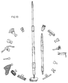
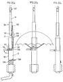
- Handle 48 may be of any suitable construction.
- handle 48 is shown in Figure 5 wherein handle frame 70 is rigidly mounted to first member 10 .
- Handle bar 72 is slidably mounted onto handle frame 70 so that the user can pull handle bar 72 toward handle frame 70 whenever it is desired to activate, for example, tongs 44 .
- handle bar 72 is biased, as by a spring (not shown) to a position away from handle frame 70 .
- Onto handle bar 72 is mounted a spool 74 onto which is wound an appropriate length of cable 46 to accommodate the varying lengths of the device in various states of extension and retraction.
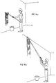
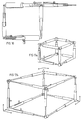
- FIG. 4 Yet another alternative embodiment of a device according to the present invention is shown in Figure 4.
- the device is related to that shown in Figure 1, except that rather than the three members being nested inside one another, the three members of Figure 4 are arranged along side of each other.
- Such a configuration may be useful, for example, in opening and closing slats of window blinds of various types.
- the slats may move through tracks or may be suspended.
Landscapes
- Engineering & Computer Science (AREA)
- General Engineering & Computer Science (AREA)
- Mechanical Engineering (AREA)
- Robotics (AREA)
- Manipulator (AREA)
- Mutual Connection Of Rods And Tubes (AREA)
- Pens And Brushes (AREA)
- Toys (AREA)
- Ladders (AREA)
- Jib Cranes (AREA)
- Fittings On The Vehicle Exterior For Carrying Loads, And Devices For Holding Or Mounting Articles (AREA)
- Helmets And Other Head Coverings (AREA)
- Harvester Elements (AREA)
- Mechanical Pencils And Projecting And Retracting Systems Therefor, And Multi-System Writing Instruments (AREA)
- Carriages For Children, Sleds, And Other Hand-Operated Vehicles (AREA)
- Devices For Indicating Variable Information By Combining Individual Elements (AREA)
- Storing, Repeated Paying-Out, And Re-Storing Of Elongated Articles (AREA)
- Seal Device For Vehicle (AREA)
- Supplying Of Containers To The Packaging Station (AREA)
- Ultra Sonic Daignosis Equipment (AREA)
- Handcart (AREA)
- Purses, Travelling Bags, Baskets, Or Suitcases (AREA)
- Accessories Of Cameras (AREA)
- Preparation Of Compounds By Using Micro-Organisms (AREA)
- Peptides Or Proteins (AREA)
- Prostheses (AREA)
Claims (32)
- Tragbare aus-/einfahrbare Vorrichtung, die dafür ausgebildet ist, in der Hand gehalten zu werden, und geeignet ist zur Bewegung eines an der Vorrichtung befestigten Werkzeuges oder anderen Objekts, wobei die Vorrichtung aufweist:(a) ein erstes Teil (10, 200);(b) ein zweites Teil (12, 202), das relativ zu dem ersten Teil (10, 200) bewegbar ist;(c) ein drittes Teil (14, 204), das relativ zu dem ersten Teil (10, 200) und zu dem zweiten Teil (12, 202) bewegbar ist;(d) eine flexible Verbindereinrichtung (30, 32, 206), die an einem hinteren Teil des dritten Teils (14, 204) befestigt ist, wobei dieflexible Verbindereinrichtung (30, 32, 206) durch eine erste Stelle (34) des zweiten Teils (12, 202) gehalten und relativ zu derselben bewegbar ist, wobei die flexible Verbindereinrichtung (30, 32, 206) an einer ersten Befestigungsstelle des ersten Teils (10, 200) befestigt ist, so daß eine nach vorn gerichtete Bewegung des zweiten Teils (12, 202) zu einer nach vorn gerichteten Bewegung des dritten Teils (14, 204) führt,
dadurch gekennzeichnet, daß(e) die flexible Verbindereinrichtung (30, 32, 206) durch eine zweite Stelle (36) des zweiten Teils (12, 202) gehalten ist und relativ zu derselben bewegbar ist, wobei die zweite Stelle (36) des zweiten Teils (12, 202) hinter der ersten Stelle (34) des zweiten Teils (12, 202) ist, wobei die flexible Verbindereinrichtung (30, 32, 206) an einer zweiten Befestigungsstelle des ersten Teils (10, 200) befestigt ist, so daß eine nach hinten gerichtete Bewegung des zweiten Teils (12, 202) zu einer nach hinten gerichteten Bewegung des dritten Teils (14, 204) führt. - Vorrichtung nach Anspruch 1, dadurch gekennzeichnet, daß die flexible Verbindereinrichtung (30, 32) einen ersten flexiblen Verbinder (30) und einen zweiten flexiblen Verbinder (32) aufweist.
- Vorrichtung nach Anspruch 2, dadurch gekennzeichnet, daß sie weiter aufweist:(f) einen dritten flexiblen Verbinder (16), der an einem hinteren Teil (36) des zweiten Teils (12) befestigt ist, wobei der dritte flexible Verbinder (16) durch eine erste Stelle des ersten Teils (10) gehalten ist und relativ zu derselben bewegbar ist;(g) einen vierten flexiblen Verbinder (22), der an einem hinteren Teil (36) des zweiten Teils (12) befestigt ist, wobei der vierte flexible Verbinder (22) durch eine zweite Stelle des ersten Teils (10) gehalten ist und relativ zu derselben bewegbar ist, wobei die zweite Stelle hinter der ersten Stelle ist,
wobei der dritte flexible Verbinder (16) und der vierte flexible Verbinder (22) durch einen Koppler miteinander gekoppelt sind, der einen Handgriff (28) aufweist, so daß der dritte flexible Verbinder (16), der vierte flexible Verbinder (22) und das zweite Teil (12) sich alle gleichzeitig bewegen, wenn der Koppler (28) axial längs des ersten Teils (10) bewegt wird, wobei der Handgriff (28) weiter dazu dient, die Vorrichtung zu positionieren und zu stabilisieren. - Vorrichtung nach Anspruch 1, dadurch gekennzeichnet, daß das erste Teil (10) mit einem Längsschlitz (50) versehen ist und weiter einen starren Verbinder (52) aufweist, der an einem hinteren Teil des zweiten Teils (12) befestigt ist, wobei der starre Verbinder (52) in dem Längsschlitz (50) des ersten Teils (10) verschiebbar ist, so daß das zweite Teil (12) immer dann bewegt wird, wenn der starre Verbinder (52) bewegt wird.
- Vorrichtung nach Anspruch 1, dadurch gekennzeichnet, daß der starre Verbinder (52) einen Handgriff (54) hat, der so angeordnet ist, daß er an einer festen Stelle (55) verriegelbar ist.
- Vorrichtung nach Anspruch 1, dadurch gekennzeichnet, daß die flexible Verbindereinrichtung ein durchgehendes Band (206) bildet oder zwei flexible Verbinder (30, 32) aufweist, die eine Schleife bilden.
- Vorrichtung nach Anspruch 3, dadurch gekennzeichnet, daß der Handgriff (28, 54) so angeordnet ist, daß er an einer Stelle (38, 55) an dem ersten Teil (10) verriegelbar ist.
- Vorrichtung nach einem der Ansprüche 1 bis 7, dadurch gekennzeichnet, daß das erste Teil (10), das zweite Teil (12) und das dritte Teil (14) ineinander geschachtelt sind, so daß das dritte Teil (14) innerhalb des zweiten Teils (12) und das zweite Teil (12) innerhalb des ersten Teils (10) ist.
- Vorrichtung nach Anspruch 8, dadurch gekennzeichnet, daß das erste Teil (10), das zweite Teil (12) und das dritte Teil (14) ungefähr zylindrisch sind.
- Vorrichtung nach einem der Ansprüche 1 bis 7, dadurch gekennzeichnet, daß das erste Teil (10), das zweite Teil (12) und das dritte Teil (14) benachbart zueinander angeordnet sind.
- Vorrichtung nach Anspruch 2, dadurch gekennzeichnet, daß die erste Befestigungsstelle und die zweite Befestigungsstelle auf entgegengesetzten Seiten des ersten Teils (10) sind.
- Vorrichtung nach einem der Ansprüche 1 bis 11, dadurch gekennzeichnet, daß die flexiblen Verbinder Seile sind.
- Vorrichtung nach einem der Ansprüche 1 bis 12, dadurch gekennzeichnet, daß die erste Stelle des ersten Teils der vordere Rand des ersten Teils (10) ist und daß die zweite Stelle des ersten Teils (10) der hintere Rand des ersten Teils (10) ist.
- Vorrichtung nach einem der Ansprüche 1 bis 13, dadurch gekennzeichnet, daß die erste Stelle des zweiten Teils (12) ein erstes Loch in dem zweiten Teil (12) ist und daß die zweite Stelle des zweiten Teils (12) ein zweites Loch ist, das sich hinter dem ersten Loch befindet und sich durch das zweite Teil (12) erstreckt.
- Vorrichtung nach einem der Ansprüche 3 bis 14, dadurch gekennzeichnet, daß das Koppeln des dritten flexiblen Verbinders (16) und des vierten flexiblen Verbinders (22) mit einander durch einen beweglichen Handgriff (28, 54) erreicht wird.
- Vorrichtung nach Anspruch 15, dadurch gekennzeichnet, daß der bewegliche Handgriff (28, 54) durch eine lösbare Befestigung (38, 55) an dem ersten Teil (10) stillgesetzt werden kann.
- Vorrichtung nach einem der Ansprüche 3 bis 14, dadurch gekennzeichnet, daß das Koppeln des dritten flexiblen Verbinders (16) und des vierten flexiblen Verbinders (22) mit einander durch einen Windenmechanismus (100) erreicht wird.
- Vorrichtung nach irgendeinem vorhergehenden Anspruch, dadurch gekennzeichnet, daß sie ein Werkzeug (44) aufweist, das an wenigstens einem der Teile (10, 12, 14) befestigt ist.
- Vorrichtung nach Anspruch 18, dadurch gekennzeichnet, daß das Werkzeug (44) ein Malerpinsel, eine Farbwalze, ein Mop, eine Staubbürste, ein Schneidwerkzeug, eine Zange oder eine Befestigungsvorrichtung zum Befestigen der Vorrichtung an einem anderen Körper ist.
- Vorrichtung nach Anspruch 18, dadurch gekennzeichnet, daß das Werkzeug (44) dafür ausgebildet ist, durch den Benutzer fernbetätigt zu werden.
- Tragbare aus-/einfahrbare Vorrichtung, die dafür ausgebildet ist, in der Hand gehalten zu werden und geeignet ist zur Bewegung eines Werkzeuges oder anderen Objekts, das an der Vorrichtung befestigt ist, wobei die Vorrichtung aufweist:(a) ein erstes Teil (10, 200),(b) ein zweites Teil (12, 202), das relativ zu dem ersten Teil (10, 200) bewegbar ist,(c) ein drittes Teil (14, 204), das relativ zu dem ersten Teil (10, 200) und zu dem zweiten Teil (12, 202) bewegbar ist, und(d) eine flexible Verbindereinrichtung (75, 88, 244), die durch eine erste Stelle des zweiten Teils (12, 202) gehalten ist und relativ zu derselben bewegbar ist, wobei die flexible Verbindereinrichtung (76, 88, 244) ein erstes Rad (78, 242) betätigt, das an der ersten Stelle des zweiten Teils (12, 202) angeordnet ist, so daß eine nach vorn gerichtete Bewegung des zweiten Teils (12, 202) zu einer nach vorn gerichteten Bewegung des dritten Teils (14, 204) führt,
dadurch gekennzeichnet, daß(e) die flexible Verbindereinrichtung (76, 88, 244) durch eine zweite Stelle des zweiten Teils (12, 208) gehalten ist und relativ zu derselben bewegbar ist, wobei die zweite flexible Verbindereinrichtung (76, 88, 244) ein zweites Rad (84, 240) betätigt, das an der zweiten Stelle des zweiten Teils (12, 202) angeordnet ist, und wobei die zweite Stelle des zweiten Teils (12, 202) hinter der ersten Stelle des zweiten Teils (12, 202) ist, unddaß das erste Rad (78, 242) das dritte Teil (14, 204) erfaßt und daß das zweite Rad (84, 240) das erste Teil (10, 200) erfaßt, so daß eine nach hinten gerichtete Bewegung des zweiten Teils (12, 202) zu einer nach hinten gerichteten Bewegung des dritten Teils (14, 204) führt. - Vorrichtung nach Anspruch 21, dadurch gekennzeichnet, daß die flexible Verbindereinrichtung (244) an dem zweiten Teil (202) befestigt ist, wobei die flexible Verbindereinrichtung (244) mit dem ersten Teil (200) und mit dem dritten Teil (204) verbunden ist, so daß sich das erste und das dritte Teil (200, 204) in entgegengesetzten Richtungen relativ zu dem zweiten Teil (202) bewegen.
- Vorrichtung nach Anspruch 21 oder 22, dadurch gekennzeichnet, daß die Bewegung des ersten und des dritten Teils (200, 204) erzeugt wird, wenn das erste und das zweite Teil (200, 202) relativ zu einander bewegt werden.
- Vorrichtung nach einem der Ansprüche 21 bis 23, dadurch gekennzeichnet, daß die Bewegung des ersten und des dritten Teils (200, 204) erzeugt wird, wenn das zweite und das dritte Teil (202, 204) relativ zu einander bewegt werden.
- Vorrichtung nach Anspruch 1 oder 21, dadurch gekennzeichnet, daß wenigstens das erste oder das dritte Teil (200, 204) aus wenigstens zwei Teilen (210, 212) gebildet ist, wobei einer der Teile an der flexiblen Verbindereinrichtung (206) dauerhaft befestigt ist und wobei wenigstens ein anderer Teil lösbar ist.
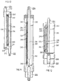
- Vorrichtung nach Anspruch 21, dadurch gekennzeichnet,daß das erste Teil (10) mit einem Längsschlitz (50) versehen ist und eine erste Zahnstange (86) hat,das zweite Teil (12) ein vorderes Ende und ein hinteres Ende hat, wobei das zweite Teil (12) ein erstes Ritzel (78) nahe dem vorderen Ende und ein zweites Ritzel (84) nahe dem hinteren Ende hat und wobei das zweite Ritzel (84) mit der ersten Zahnstange (86) in Eingriff ist,daß ein starres Verbindungsteil (52) an einem hinteren Teil des zweiten Teils (12) befestigt ist, wobei der starre Verbinder (52) in dem Längsschlitz (50) des ersten Teils (10) so verschiebbar ist, daß das zweite Teil (12) immer dann bewegt wird, wenn der starre Verbinder (50) bewegt wird, unddaß das dritte Teil (14) eine dritte Zahnstange (82) hat, die mit dem ersten Ritzel (78) in Eingriff ist, wobei das erste Ritzel (78) durch einen Seilverbinder (76) drehbar ist, der an dem ersten Teil (10) befestigt ist, so daß eine nach vom gerichtete Bewegung des zweiten Teils (12) zu einer nach vom gerichteten Bewegung des dritten Teils (14) führt, und wobei das dritte Teil (14) an dem Ritzel (84) des zweiten Teils befestigt ist, so daß eine nach vorn gerichtete Bewegung des zweiten Teils (18) zu einer nach vorn gerichteten Bewegung des dritten Teils (14) führt.
- Vorrichtung nach Anspruch 21, gekennzeichnet weiter durch eine Sensoreinrichtung zum Erfassen der Position von wenigstens einem der ersten und zweiten Teile (10, 12) relativ zu dem zweiten Teil (14).
- Vorrichtung nach Anspruch 21, dadurch gekennzeichnet, daßdas erste Teil (200) eine erste Zahnstange (224) hat,das dritte Teil (204) eine zweite Zahnstange (224) hat undein Paar Zahnräder (240, 242) auf dem zweiten Teil (202) befestigt ist, wobei die Zahnräder (240, 242) mit einander durch den flexiblen Verbinder (244) verbunden sind, wobei der flexible Verbinder (244) ein durchgehendes Band oder eine Schleife, die aus zwei flexiblen Verbindern hergestellt ist, aufweist, und wobei die Zahnräder (240, 242) die erste und die zweite Zahnstange (224) erfassen, so daß das erste und das dritte Teil (200, 204) sich in entgegengesetzten Richtungen relativ zu dem zweiten Teil (202) bewegen.
- Vorrichtung nach einem der Ansprüche 21 bis 28, dadurch gekennzeichnet, daß das erste Teil (200), das zweite Teil (202) oder das dritte Teil (204) jeweils an einem Objekt befestigt sind.
- Vorrichtung nach einem der Ansprüche 21 bis 29, dadurch gekennzeichnet, daß ein reduzierbar aufweitbares Teil (250) gleichzeitig an zwei unter dem ersten Teil (200), dem zweiten Teil (202) oder dem dritten Teil (204) ausgewählten Teilen entsprechend befestigt sein kann.
- Vorrichtung nach Anspruch 30, dadurch gekennzeichnet, daß das reduzierbar aufweitbare Teil ein hohles Rohr (250) aufweist.
- Vorrichtung nach Anspruch 1 oder 21, dadurch gekennzeichnet, daß sie eine Feder (306) enthält, um die Bewegung der Teile zu beeinflussen.
Applications Claiming Priority (3)
| Application Number | Priority Date | Filing Date | Title |
|---|---|---|---|
| US912415 | 1992-07-13 | ||
| US07/912,415 US5324086A (en) | 1991-07-24 | 1992-07-13 | Device capable of positive extension and retraction using a casading force transfer |
| PCT/US1993/006499 WO1994001254A1 (en) | 1992-07-13 | 1993-07-09 | Extendible and retractable device |
Publications (3)
| Publication Number | Publication Date |
|---|---|
| EP0650405A1 EP0650405A1 (de) | 1995-05-03 |
| EP0650405A4 EP0650405A4 (de) | 1995-08-23 |
| EP0650405B1 true EP0650405B1 (de) | 2000-03-08 |
Family
ID=25431882
Family Applications (1)
| Application Number | Title | Priority Date | Filing Date |
|---|---|---|---|
| EP93917084A Expired - Lifetime EP0650405B1 (de) | 1992-07-13 | 1993-07-09 | Tragbare, ausfahrbare und zusammenschiebbare bewegungsvorrichtung |
Country Status (23)
| Country | Link |
|---|---|
| EP (1) | EP0650405B1 (de) |
| JP (1) | JPH08500776A (de) |
| AT (1) | ATE190257T1 (de) |
| AU (1) | AU684467B2 (de) |
| BG (1) | BG99346A (de) |
| BR (1) | BR9306734A (de) |
| CA (1) | CA2139659A1 (de) |
| CZ (1) | CZ8795A3 (de) |
| DE (1) | DE69328024T2 (de) |
| DK (1) | DK0650405T3 (de) |
| ES (1) | ES2145779T3 (de) |
| FI (1) | FI950143A7 (de) |
| GR (1) | GR3033640T3 (de) |
| HU (1) | HUT75562A (de) |
| NO (1) | NO950120L (de) |
| NZ (1) | NZ254563A (de) |
| OA (1) | OA10000A (de) |
| PL (1) | PL172359B1 (de) |
| PT (1) | PT650405E (de) |
| RO (1) | RO116791B1 (de) |
| RU (1) | RU95107687A (de) |
| SK (1) | SK5195A3 (de) |
| WO (1) | WO1994001254A1 (de) |
Cited By (3)
| Publication number | Priority date | Publication date | Assignee | Title |
|---|---|---|---|---|
| DE102011116074A1 (de) * | 2011-10-18 | 2013-04-18 | Fischer Rohrtechnik Gmbh | Staubsauger-Saugrohr |
| US8894099B2 (en) | 2011-10-18 | 2014-11-25 | Fischer Rohrtechnik Gmbh | Vacuum cleaner suction pipe |
| CN107263533A (zh) * | 2017-06-21 | 2017-10-20 | 太仓望虞机械科技有限公司 | 一种结构紧凑的伸缩旋转机械手臂 |
Families Citing this family (17)
| Publication number | Priority date | Publication date | Assignee | Title |
|---|---|---|---|---|
| US20030115676A1 (en) * | 2001-12-21 | 2003-06-26 | Burton Kozak | Tool with opposing driving and telescopic pick-up functions |
| US7684694B2 (en) | 2005-05-10 | 2010-03-23 | Fromm Wayne G | Apparatus for supporting a camera and method for using the apparatus |
| US20060257138A1 (en) * | 2005-05-10 | 2006-11-16 | Fromm Wayne G | Apparatus for supporting a camera |
| ES2302486B1 (es) * | 2008-02-21 | 2009-07-27 | Jose Luis Godoy Varo | Metodo y aparato para fabricacion de tapones multicapa de corcho natural y tapon multicapa de corcho natural. |
| CN101554268B (zh) * | 2008-04-11 | 2014-05-14 | 尤尼富尔有限公司 | 伸缩式工作台支架 |
| EP2138240A1 (de) * | 2008-06-27 | 2009-12-30 | Hetra ApS | Flüssigkeitsapplikator und Verfahren zum Auftragen von Flüssigkeit auf eine Fläche |
| CN102320042B (zh) * | 2011-09-09 | 2014-01-08 | 北京工业大学 | 嵌套式自动往复机械爪 |
| ITRE20130014A1 (it) * | 2013-03-04 | 2014-09-05 | Annovi Reverberi Spa | Lancia erogatrice estensibile per dispositivi di lavaggio |
| CN103682784A (zh) * | 2013-12-31 | 2014-03-26 | 江苏金铁人自动化科技有限公司 | 一种可以调节高度的移动电源插座 |
| CN108432462B (zh) * | 2018-04-18 | 2023-10-03 | 广东工业大学 | 一种摇臂式簇状水果采摘装置 |
| CN109176449A (zh) * | 2018-10-10 | 2019-01-11 | 刘书勇 | 一种便捷式伸缩机械臂及其使用方法 |
| CN110547094A (zh) * | 2019-09-06 | 2019-12-10 | 贵州航天智慧农业有限公司 | 一种微型三自由度采摘机械手 |
| SE2050045A1 (en) * | 2020-01-21 | 2021-07-22 | Orbishaft Ab | Portable shaft system |
| CN111972130B (zh) * | 2020-08-26 | 2022-07-01 | 上海大学 | 一种中空可伸缩的机械臂 |
| EP4288249A4 (de) * | 2022-03-29 | 2024-12-25 | Srivastava, Sudhir Prem | Teleskopsäulenanordnung in einem roboterarmsystem |
| PL440998A1 (pl) * | 2022-04-22 | 2023-10-23 | Portman Lights Spółka Z Ograniczoną Odpowiedzialnością | Urządzenie do łączenia osprzętu scenicznego |
| DE102023105940A1 (de) | 2023-03-09 | 2024-09-12 | Alfred Kärcher SE & Co. KG | Gerät und modul und verwendung eines moduls |
Family Cites Families (18)
| Publication number | Priority date | Publication date | Assignee | Title |
|---|---|---|---|---|
| US161010A (en) * | 1875-03-23 | Improvement in extension-ladders | ||
| US326336A (en) * | 1885-09-15 | Teebitoby | ||
| US336414A (en) * | 1886-02-16 | Pike escape | ||
| US926642A (en) * | 1907-12-05 | 1909-06-29 | Isaac R Concoff | Ladder. |
| US925822A (en) * | 1908-09-14 | 1909-06-22 | Horace Mote | Extension-ladder. |
| US1384761A (en) * | 1920-04-14 | 1921-07-19 | James H Jessup | Cable-tie hanger |
| US2641401A (en) * | 1950-05-13 | 1953-06-09 | James Herschel | Ladder |
| US3213574A (en) * | 1961-12-11 | 1965-10-26 | Melbye | Elevating mechanisms |
| US3248831A (en) * | 1962-01-03 | 1966-05-03 | Craig Systems Corp | Telescoping antenna mast |
| FR1492931A (fr) * | 1966-05-11 | 1967-08-25 | Grue à flèche télescopique | |
| FR1580387A (de) * | 1968-07-03 | 1969-09-05 | ||
| US3534867A (en) * | 1968-07-25 | 1970-10-20 | Harnischfeger Corp | Compensating boom hoist cable system for a telescopic boom for cranes or the like |
| US3836011A (en) * | 1970-01-31 | 1974-09-17 | T Sakamoto | Extensible boom |
| NO140922C (no) * | 1976-09-03 | 1979-12-12 | Nor Mar A S | Teleskoparm. |
| FR2369993A1 (fr) * | 1976-11-08 | 1978-06-02 | Laing & Son Ltd John | Dispositif telescopique |
| US4406375A (en) * | 1980-07-02 | 1983-09-27 | Jlg Industries Inc. | Telescopic boom construction |
| US4388033A (en) * | 1981-03-16 | 1983-06-14 | Eaton Corporation | Shuttle assembly |
| US4575976A (en) * | 1983-06-24 | 1986-03-18 | Machine Products Corporation | Extension and retraction system for boom apparatus |
-
1993
- 1993-07-09 SK SK51-95A patent/SK5195A3/sk unknown
- 1993-07-09 PL PL93307161A patent/PL172359B1/pl unknown
- 1993-07-09 NZ NZ254563A patent/NZ254563A/xx unknown
- 1993-07-09 AU AU46719/93A patent/AU684467B2/en not_active Ceased
- 1993-07-09 AT AT93917084T patent/ATE190257T1/de not_active IP Right Cessation
- 1993-07-09 ES ES93917084T patent/ES2145779T3/es not_active Expired - Lifetime
- 1993-07-09 DK DK93917084T patent/DK0650405T3/da active
- 1993-07-09 BR BR9306734A patent/BR9306734A/pt not_active Application Discontinuation
- 1993-07-09 DE DE69328024T patent/DE69328024T2/de not_active Expired - Fee Related
- 1993-07-09 WO PCT/US1993/006499 patent/WO1994001254A1/en not_active Ceased
- 1993-07-09 FI FI950143A patent/FI950143A7/fi not_active Application Discontinuation
- 1993-07-09 CZ CZ9587A patent/CZ8795A3/cs unknown
- 1993-07-09 JP JP5505605A patent/JPH08500776A/ja active Pending
- 1993-07-09 CA CA002139659A patent/CA2139659A1/en not_active Abandoned
- 1993-07-09 RU RU95107687/02A patent/RU95107687A/ru unknown
- 1993-07-09 HU HU9500062A patent/HUT75562A/hu active IP Right Revival
- 1993-07-09 EP EP93917084A patent/EP0650405B1/de not_active Expired - Lifetime
- 1993-07-09 PT PT93917084T patent/PT650405E/pt unknown
- 1993-07-09 RO RO95-00046A patent/RO116791B1/ro unknown
-
1995
- 1995-01-11 BG BG99346A patent/BG99346A/xx unknown
- 1995-01-12 NO NO950120A patent/NO950120L/no unknown
- 1995-01-12 OA OA60602A patent/OA10000A/en unknown
-
2000
- 2000-06-08 GR GR20000401327T patent/GR3033640T3/el not_active IP Right Cessation
Cited By (3)
| Publication number | Priority date | Publication date | Assignee | Title |
|---|---|---|---|---|
| DE102011116074A1 (de) * | 2011-10-18 | 2013-04-18 | Fischer Rohrtechnik Gmbh | Staubsauger-Saugrohr |
| US8894099B2 (en) | 2011-10-18 | 2014-11-25 | Fischer Rohrtechnik Gmbh | Vacuum cleaner suction pipe |
| CN107263533A (zh) * | 2017-06-21 | 2017-10-20 | 太仓望虞机械科技有限公司 | 一种结构紧凑的伸缩旋转机械手臂 |
Also Published As
| Publication number | Publication date |
|---|---|
| EP0650405A4 (de) | 1995-08-23 |
| RU95107687A (ru) | 1997-05-27 |
| SK5195A3 (en) | 1996-03-06 |
| JPH08500776A (ja) | 1996-01-30 |
| NO950120D0 (no) | 1995-01-12 |
| CA2139659A1 (en) | 1994-01-20 |
| FI950143L (fi) | 1995-03-10 |
| PL172359B1 (pl) | 1997-09-30 |
| NZ254563A (en) | 1998-12-23 |
| CZ8795A3 (en) | 1996-03-13 |
| FI950143A0 (fi) | 1995-01-12 |
| EP0650405A1 (de) | 1995-05-03 |
| HU9500062D0 (en) | 1995-03-28 |
| ATE190257T1 (de) | 2000-03-15 |
| GR3033640T3 (en) | 2000-10-31 |
| HUT75562A (en) | 1997-05-28 |
| WO1994001254A1 (en) | 1994-01-20 |
| RO116791B1 (ro) | 2001-06-29 |
| DE69328024D1 (de) | 2000-04-13 |
| NO950120L (no) | 1995-02-23 |
| ES2145779T3 (es) | 2000-07-16 |
| AU684467B2 (en) | 1997-12-18 |
| BR9306734A (pt) | 1998-12-08 |
| OA10000A (en) | 1996-03-29 |
| DK0650405T3 (da) | 2000-08-21 |
| PT650405E (pt) | 2000-08-31 |
| AU4671993A (en) | 1994-01-31 |
| DE69328024T2 (de) | 2000-11-23 |
| BG99346A (bg) | 1995-09-29 |
| FI950143A7 (fi) | 1995-03-10 |
| PL307161A1 (en) | 1995-05-02 |
Similar Documents
| Publication | Publication Date | Title |
|---|---|---|
| US5881601A (en) | Extendible and retractable reaching tool | |
| EP0650405B1 (de) | Tragbare, ausfahrbare und zusammenschiebbare bewegungsvorrichtung | |
| US5322334A (en) | Device for positively telescopically extending and retracting | |
| RU2446267C1 (ru) | Установка и способы для манипуляций с трубами | |
| US5755306A (en) | Personnel lift incorporating an outreach mechanism for an aerial work platform | |
| JP4350040B2 (ja) | 折り畳み可能な傘状遮蔽体を備える移動式シェルタ | |
| EP1753690B1 (de) | Masthebemaschine | |
| US20110056035A1 (en) | Superior apparatus for cleaning windows | |
| JPH05229779A (ja) | 遠隔操作つき駆動化荷物係合装置 | |
| EP2639382A1 (de) | Arbeitsplattform | |
| US7195102B2 (en) | Telescopic stool | |
| US20100326770A1 (en) | Accessory mounting | |
| US20230313612A1 (en) | Wheeled platform system | |
| CN118139559A (zh) | 辅助关节炎患者的、五机合一的伞篷 | |
| WO1996024000A1 (en) | Extensible and retractable elements and various uses for the elements | |
| WO1997000404A9 (en) | Universal tool support system | |
| WO1997000404A1 (en) | Universal tool support system | |
| EP4310042A1 (de) | Vorrichtung zum entfalten von aufrollbaren spulen | |
| EP0805929A1 (de) | Ausfahrbare und zusammenschiebbare elemente und unterschiedliche verwendungen der elemente | |
| AU1246800A (en) | Extensible and retractable elements and various uses for the elements | |
| US295929A (en) | Fire-escape | |
| US6454329B1 (en) | Device for removing leaves and other debris from an overhead gutter | |
| KR200313938Y1 (ko) | 주방용 사다리 | |
| CN114568995B (zh) | 一种基于引导杆结构的高层幕墙自动清洗机器人 | |
| WO2006007628A9 (en) | Cable stand |
Legal Events
| Date | Code | Title | Description |
|---|---|---|---|
| PUAI | Public reference made under article 153(3) epc to a published international application that has entered the european phase |
Free format text: ORIGINAL CODE: 0009012 |
|
| 17P | Request for examination filed |
Effective date: 19950113 |
|
| AK | Designated contracting states |
Kind code of ref document: A1 Designated state(s): AT BE CH DE DK ES FR GB GR IE IT LI LU MC NL PT SE |
|
| RAP1 | Party data changed (applicant data changed or rights of an application transferred) |
Owner name: HAMMER, MORDECHAI |
|
| A4 | Supplementary search report drawn up and despatched | ||
| AK | Designated contracting states |
Kind code of ref document: A4 Designated state(s): AT BE CH DE DK ES FR GB GR IE IT LI LU MC NL PT SE |
|
| 17Q | First examination report despatched |
Effective date: 19970527 |
|
| GRAG | Despatch of communication of intention to grant |
Free format text: ORIGINAL CODE: EPIDOS AGRA |
|
| GRAG | Despatch of communication of intention to grant |
Free format text: ORIGINAL CODE: EPIDOS AGRA |
|
| GRAH | Despatch of communication of intention to grant a patent |
Free format text: ORIGINAL CODE: EPIDOS IGRA |
|
| GRAH | Despatch of communication of intention to grant a patent |
Free format text: ORIGINAL CODE: EPIDOS IGRA |
|
| GRAA | (expected) grant |
Free format text: ORIGINAL CODE: 0009210 |
|
| AK | Designated contracting states |
Kind code of ref document: B1 Designated state(s): AT BE CH DE DK ES FR GB GR IE IT LI LU MC NL PT SE |
|
| REF | Corresponds to: |
Ref document number: 190257 Country of ref document: AT Date of ref document: 20000315 Kind code of ref document: T |
|
| REG | Reference to a national code |
Ref country code: CH Ref legal event code: EP |
|
| REF | Corresponds to: |
Ref document number: 69328024 Country of ref document: DE Date of ref document: 20000413 |
|
| REG | Reference to a national code |
Ref country code: IE Ref legal event code: FG4D |
|
| ITF | It: translation for a ep patent filed | ||
| PGFP | Annual fee paid to national office [announced via postgrant information from national office to epo] |
Ref country code: PT Payment date: 20000705 Year of fee payment: 8 |
|
| PG25 | Lapsed in a contracting state [announced via postgrant information from national office to epo] |
Ref country code: AT Free format text: LAPSE BECAUSE OF NON-PAYMENT OF DUE FEES Effective date: 20000709 |
|
| REG | Reference to a national code |
Ref country code: ES Ref legal event code: FG2A Ref document number: 2145779 Country of ref document: ES Kind code of ref document: T3 |
|
| ET | Fr: translation filed | ||
| REG | Reference to a national code |
Ref country code: DK Ref legal event code: T3 |
|
| PGFP | Annual fee paid to national office [announced via postgrant information from national office to epo] |
Ref country code: DK Payment date: 20000829 Year of fee payment: 8 |
|
| REG | Reference to a national code |
Ref country code: PT Ref legal event code: SC4A Free format text: AVAILABILITY OF NATIONAL TRANSLATION Effective date: 20000608 |
|
| PLBE | No opposition filed within time limit |
Free format text: ORIGINAL CODE: 0009261 |
|
| STAA | Information on the status of an ep patent application or granted ep patent |
Free format text: STATUS: NO OPPOSITION FILED WITHIN TIME LIMIT |
|
| PGFP | Annual fee paid to national office [announced via postgrant information from national office to epo] |
Ref country code: MC Payment date: 20010126 Year of fee payment: 8 Ref country code: IE Payment date: 20010126 Year of fee payment: 8 |
|
| PGFP | Annual fee paid to national office [announced via postgrant information from national office to epo] |
Ref country code: LU Payment date: 20010129 Year of fee payment: 8 |
|
| PGFP | Annual fee paid to national office [announced via postgrant information from national office to epo] |
Ref country code: ES Payment date: 20010131 Year of fee payment: 8 Ref country code: GR Payment date: 20010131 Year of fee payment: 8 |
|
| 26N | No opposition filed | ||
| PGFP | Annual fee paid to national office [announced via postgrant information from national office to epo] |
Ref country code: BE Payment date: 20010315 Year of fee payment: 8 |
|
| PG25 | Lapsed in a contracting state [announced via postgrant information from national office to epo] |
Ref country code: DE Free format text: LAPSE BECAUSE OF NON-PAYMENT OF DUE FEES Effective date: 20010501 |
|
| PG25 | Lapsed in a contracting state [announced via postgrant information from national office to epo] |
Ref country code: LU Free format text: LAPSE BECAUSE OF NON-PAYMENT OF DUE FEES Effective date: 20010709 Ref country code: IE Free format text: LAPSE BECAUSE OF NON-PAYMENT OF DUE FEES Effective date: 20010709 Ref country code: DK Free format text: LAPSE BECAUSE OF NON-PAYMENT OF DUE FEES Effective date: 20010709 |
|
| PG25 | Lapsed in a contracting state [announced via postgrant information from national office to epo] |
Ref country code: ES Free format text: LAPSE BECAUSE OF NON-PAYMENT OF DUE FEES Effective date: 20010710 |
|
| PG25 | Lapsed in a contracting state [announced via postgrant information from national office to epo] |
Ref country code: GR Free format text: LAPSE BECAUSE OF NON-PAYMENT OF DUE FEES Effective date: 20010731 Ref country code: BE Free format text: LAPSE BECAUSE OF NON-PAYMENT OF DUE FEES Effective date: 20010731 |
|
| BERE | Be: lapsed |
Owner name: HAMMER MORDECHAI Effective date: 20010731 |
|
| PG25 | Lapsed in a contracting state [announced via postgrant information from national office to epo] |
Ref country code: PT Free format text: LAPSE BECAUSE OF NON-PAYMENT OF DUE FEES Effective date: 20020131 |
|
| PG25 | Lapsed in a contracting state [announced via postgrant information from national office to epo] |
Ref country code: MC Free format text: LAPSE BECAUSE OF NON-PAYMENT OF DUE FEES Effective date: 20020201 |
|
| GBPC | Gb: european patent ceased through non-payment of renewal fee |
Effective date: 20010709 |
|
| REG | Reference to a national code |
Ref country code: GB Ref legal event code: 728V |
|
| REG | Reference to a national code |
Ref country code: DK Ref legal event code: EBP |
|
| REG | Reference to a national code |
Ref country code: IE Ref legal event code: MM4A |
|
| REG | Reference to a national code |
Ref country code: PT Ref legal event code: MM4A Free format text: LAPSE DUE TO NON-PAYMENT OF FEES Effective date: 20020131 |
|
| REG | Reference to a national code |
Ref country code: FR Ref legal event code: ST |
|
| REG | Reference to a national code |
Ref country code: GB Ref legal event code: 728Y |
|
| REG | Reference to a national code |
Ref country code: FR Ref legal event code: D3 |
|
| REG | Reference to a national code |
Ref country code: FR Ref legal event code: ST |
|
| REG | Reference to a national code |
Ref country code: FR Ref legal event code: D3 |
|
| REG | Reference to a national code |
Ref country code: ES Ref legal event code: FD2A Effective date: 20020810 |
|
| PG25 | Lapsed in a contracting state [announced via postgrant information from national office to epo] |
Ref country code: IT Free format text: LAPSE BECAUSE OF NON-PAYMENT OF DUE FEES;WARNING: LAPSES OF ITALIAN PATENTS WITH EFFECTIVE DATE BEFORE 2007 MAY HAVE OCCURRED AT ANY TIME BEFORE 2007. THE CORRECT EFFECTIVE DATE MAY BE DIFFERENT FROM THE ONE RECORDED. Effective date: 20050709 |
|
| PGFP | Annual fee paid to national office [announced via postgrant information from national office to epo] |
Ref country code: CH Payment date: 20060125 Year of fee payment: 13 |
|
| PGFP | Annual fee paid to national office [announced via postgrant information from national office to epo] |
Ref country code: SE Payment date: 20060126 Year of fee payment: 13 |
|
| PG25 | Lapsed in a contracting state [announced via postgrant information from national office to epo] |
Ref country code: SE Free format text: LAPSE BECAUSE OF NON-PAYMENT OF DUE FEES Effective date: 20060710 |
|
| PG25 | Lapsed in a contracting state [announced via postgrant information from national office to epo] |
Ref country code: LI Free format text: LAPSE BECAUSE OF NON-PAYMENT OF DUE FEES Effective date: 20060731 Ref country code: CH Free format text: LAPSE BECAUSE OF NON-PAYMENT OF DUE FEES Effective date: 20060731 |
|
| REG | Reference to a national code |
Ref country code: CH Ref legal event code: PL |
|
| EUG | Se: european patent has lapsed | ||
| REG | Reference to a national code |
Ref country code: FR Ref legal event code: ST Effective date: 20070330 |
|
| REG | Reference to a national code |
Ref country code: FR Ref legal event code: D3 |
|
| PGFP | Annual fee paid to national office [announced via postgrant information from national office to epo] |
Ref country code: NL Payment date: 20080129 Year of fee payment: 15 |
|
| PGFP | Annual fee paid to national office [announced via postgrant information from national office to epo] |
Ref country code: FR Payment date: 20080129 Year of fee payment: 15 |
|
| NLV4 | Nl: lapsed or anulled due to non-payment of the annual fee |
Effective date: 20090201 |
|
| REG | Reference to a national code |
Ref country code: FR Ref legal event code: ST Effective date: 20090331 |
|
| PG25 | Lapsed in a contracting state [announced via postgrant information from national office to epo] |
Ref country code: NL Free format text: LAPSE BECAUSE OF NON-PAYMENT OF DUE FEES Effective date: 20090201 |
|
| PGFP | Annual fee paid to national office [announced via postgrant information from national office to epo] |
Ref country code: GB Payment date: 20090128 Year of fee payment: 16 |
|
| PG25 | Lapsed in a contracting state [announced via postgrant information from national office to epo] |
Ref country code: FR Free format text: LAPSE BECAUSE OF NON-PAYMENT OF DUE FEES Effective date: 20080731 |
|
| GBPC | Gb: european patent ceased through non-payment of renewal fee |
Effective date: 20090709 |
|
| PG25 | Lapsed in a contracting state [announced via postgrant information from national office to epo] |
Ref country code: GB Free format text: LAPSE BECAUSE OF NON-PAYMENT OF DUE FEES Effective date: 20090709 |