EP0650212B1 - Winkelstück für Hohlleiterverbindungen - Google Patents
Winkelstück für Hohlleiterverbindungen Download PDFInfo
- Publication number
- EP0650212B1 EP0650212B1 EP94110572A EP94110572A EP0650212B1 EP 0650212 B1 EP0650212 B1 EP 0650212B1 EP 94110572 A EP94110572 A EP 94110572A EP 94110572 A EP94110572 A EP 94110572A EP 0650212 B1 EP0650212 B1 EP 0650212B1
- Authority
- EP
- European Patent Office
- Prior art keywords
- connection
- waveguide tube
- angle piece
- waveguide
- insertion groove
- Prior art date
- Legal status (The legal status is an assumption and is not a legal conclusion. Google has not performed a legal analysis and makes no representation as to the accuracy of the status listed.)
- Expired - Lifetime
Links
- 238000003780 insertion Methods 0.000 claims description 17
- 230000037431 insertion Effects 0.000 claims description 17
- 238000004519 manufacturing process Methods 0.000 claims description 7
- 238000000034 method Methods 0.000 claims description 5
- 238000004512 die casting Methods 0.000 claims description 4
- 239000002184 metal Substances 0.000 claims description 3
- 229910000679 solder Inorganic materials 0.000 claims description 3
- 239000000853 adhesive Substances 0.000 claims description 2
- 230000001070 adhesive effect Effects 0.000 claims description 2
- 230000001154 acute effect Effects 0.000 claims 1
- 238000005495 investment casting Methods 0.000 description 4
- 238000010276 construction Methods 0.000 description 3
- 238000005266 casting Methods 0.000 description 2
- 238000005452 bending Methods 0.000 description 1
- 238000011161 development Methods 0.000 description 1
- 230000018109 developmental process Effects 0.000 description 1
- 239000003292 glue Substances 0.000 description 1
- 238000005476 soldering Methods 0.000 description 1
- 230000007704 transition Effects 0.000 description 1
- 238000011144 upstream manufacturing Methods 0.000 description 1
Images

Classifications
-
- H—ELECTRICITY
- H01—ELECTRIC ELEMENTS
- H01P—WAVEGUIDES; RESONATORS, LINES, OR OTHER DEVICES OF THE WAVEGUIDE TYPE
- H01P1/00—Auxiliary devices
- H01P1/02—Bends; Corners; Twists
- H01P1/022—Bends; Corners; Twists in waveguides of polygonal cross-section
- H01P1/027—Bends; Corners; Twists in waveguides of polygonal cross-section in the H-plane
-
- H—ELECTRICITY
- H01—ELECTRIC ELEMENTS
- H01P—WAVEGUIDES; RESONATORS, LINES, OR OTHER DEVICES OF THE WAVEGUIDE TYPE
- H01P1/00—Auxiliary devices
- H01P1/04—Fixed joints
- H01P1/042—Hollow waveguide joints
Definitions
- the invention relates to an elbow for Waveguide connections in the preamble of claim 1 specified type.
- Contra-angles and elbows for waveguide connections serve to change the direction of the energy flow in the waveguide as free of reflections as possible. While this takes place continuously in elbows, the change of direction in elbows is carried out abruptly.
- the bending or kinking can take place in the E plane as well as in the H plane. In the case of contra-angle handpieces, lower reflection factors are obtained at a 45 ° position or by multiple kinking.
- elbows of the type mentioned are in one piece and have a closed design. Thereby conditionally they are manufactured as investment castings. Investment casting is however very much due to its one-off manufacturing process expensive.
- the invention has for its object an elbow for waveguide connections of the type mentioned constructively so that its manufacture by more cost-effective procedure becomes possible.
- the task is for an elbow Waveguide connections in the preamble of claim 1 defined genus according to the invention by the features in Characteristic part of claim 1 solved.
- the contra-angle handpiece according to the invention is characterized by a one-sided open construction from what the manufacture in one Casting process with reusable molds, e.g. B. Die casting process allowed.
- the open form the workpiece is replaced by the one used Waveguide tube completed, so that again closed elbow is created.
- the second advanced waveguide tube is then attached to it trained end flange on the flange surface of the Elbow placed so that it is the connection opening coaxially encloses, the inner contour of the Waveguide tube is flush with the connection opening.
- the Manufacturing costs for the contra-angle can be z. B. at Transition from investment casting to die casting up to reduce to 10%.
- the waveguide tube in the insertion groove of the cap are the clear dimensions of the coaxial to the connection opening Insert groove to double the wall thickness of the insert Waveguide tube chosen larger than the corresponding clear dimensions of the connection opening. This is ensures that the inner contour of the waveguide tube is flush with the connection opening and none reflective edges are present inside the waveguide.
- the waveguide tube inserted in the insertion groove is included the cap is electrically and mechanically firmly connected, what with a metal conductive adhesive or by soldering with a conductive solder can be accomplished.
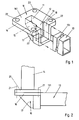
- Angle piece 10 for a 90 ° deflection in the H plane has in a known manner two connection openings 11, 12 for each a continuative, rectangular one Waveguide tube 13, 14 (FIG. 2) and a deflection surface 15 for the low reflection reflection of the energy flow from Waveguide tube 13 to the waveguide tube 14 or vice versa.
- the connection openings 11, 12 are arranged relative to one another that their normals are perpendicular to each other.
- the Deflection surface 15 is symmetrical to the connection openings 11, 12 aligned, the normals of which an angle of 45 ° to the normals of the connection openings 11, 12 includes.
- the angle piece 10 has a flange 16 with a Flange surface 161 for laying one with the continuing waveguide tube 14 firmly connected End flange 20 (Fig. 2) and one piece on Flange 16 molded cap 17.
- a flange surface 161 In the flange surface 161 is the connection opening 11 and in the cap 17 Connection opening 12 and the deflection surface 15 are formed.
- the cap 17 In the cap 17 there is an opening towards the flange surface 161 U-shaped insertion groove 18 molded into the Connection opening 12 is immediately upstream.
- the for Connection opening 12 coaxial insertion groove 18 is used positive reception of an end section of the continuing waveguide tube 13 and is dimensioned such that when the waveguide tube 13 is inserted, the inner contour of the Waveguide tube 13 flush with the connection opening 12 and the outer contour of the insertion groove 18 terminating Tube wall 131 of the further waveguide tube 13 is flush with flange surface 161. To realize this the clear dimensions of the insertion groove 18 selected so that they double the wall thickness of the continuing Waveguide tube 13 are larger than the corresponding ones clear dimensions of the connection opening 12.
- the angle piece 10 described has by the described constructive design a design open on one side, so that it is easily made in a mold and without Destroying the casting tool can be demolded.
- a Mold can thus a variety of elbows, e.g. B. in the die casting process, rationally manufactured, so that the manufacturing costs compared to a production in Investment casting processes can be extremely reduced.
- a waveguide connection (Fig. 2) the further waveguide tube 13 with his End section in the insertion groove 18 in the angle piece 10 used so that it is with its end face on the Connects opening 12 surrounding shoulder (19). Then the waveguide tube 13 in the insertion groove 18 mechanically set, while at the same time on an electrically conductive Connection is respected.
- This setting can for example by an electrically conductive Metal glue is made on the adjacent one Surfaces of insertion groove 18 and waveguide tube 13 in front Inserting the waveguide tube 13 is applied.
- the Waveguide tube 13 can also be electrically conductive solder are soldered into the insertion groove 18. Thereafter, as shown in Fig.
- Fig. 3 is an angle piece 10 'for one Waveguide connection with a 90 ° deflection in the E plane shown.
- this contra-angle 10 coincides the angle piece 10 in Fig. 1, so that the same Provide construction elements with the same reference numerals are.
- the invention is not based on those described above Embodiments limited. So instead of the a deflecting surface 15 also several deflecting surfaces are provided be in turn symmetrical to the connection openings 11, 12 can be arranged. With an arrangement of three consecutive deflection surfaces are the kink angles of the individual deflection surfaces to each other 26.3 °, 37.4 ° and 26.3 °.
Landscapes
- Coupling Device And Connection With Printed Circuit (AREA)
- Optical Integrated Circuits (AREA)
- Waveguide Connection Structure (AREA)
Description
- Fig. 1
- eine perspektivische Ansicht eines Winkelstücks für eine Hohlleiterverbindung in der H-Ebene mit einem darin einzusetzenden weiterführenden Hohlleiterrohr,
- Fig. 2
- eine Seitenansicht einer mit dem Winkelstück gemäß Fig. 1 hergestellten Hohlleiterverbindung mit 90° -Umlenkung,
- Fig. 3
- eine perspektivische Ansicht eines Winkelstücks in der E-Ebene mit darin einzusetzendem weiterführenden Hohlleiterrohr.
Claims (7)
- Winkelstück für Hohlleiterverbindungen mit zwei Anschlußöffnungen (11, 12) für jeweils ein Hohlleiterrohr (13, 14), deren Normalen rechtwinklig zueinander ausgerichtet sind, und mit mindestens einer zwischen den Anschlußöffnungen (11, 12) sich befindlichen Umlenkfläche (15), deren Normale einen spitzen Winkel zu den Normalen der Anschlußöffnungen (11, 12) einschließt, dadurch gekennzeichnet, daß die eine Anschlußöffnung (11) in der Flanschfläche (161) eines Anschlußflansches (16) angeordnet ist und die andere Anschlußöffnung (12) sowie die Umlenkfläche (15) in einer mit dem Anschlußflansch (16) einstückigen Kappe (17) ausgebildet sind und daß in der Kappe (17) der Anschlußöffnung (12) unmittelbar vorgeordnet eine zur Flanschfläche (161) hin offene Einstecknut (18) zur formschlüssigen Aufnahme eines Endabschnitts eines Hohlleiterrohrs (13) so ausgeformt ist, daß bei eingesetztem Hohlleiterrohr (13) die Innenkontur des Hohlleiterrohrs (13) bündig mit der Anschlußöffnung (12) und die Außenkontur der die Einstecknut (18) abschließenden Rohrwand (131) des Hohlleiterrohrs (13) bündig mit der Flanschfläche (161) ist.
- Winkelstück nach Anspruch 1, dadurch gekennzeichnet, daß die lichten Abmessungen der zur Anschlußöffnung (12) koaxialen Einstecknut (18) um die doppelte Wandstärke des einzusetzenden Hohlleiterrohrs (13) größer gewählt sind als die entsprechenden lichten Maße der Anschlußöffnung (12).
- Winkelstück nach Anspruch 1 oder 2, dadurch gekennzeichnet, daß der in die Einstecknut (18) eingesetzte Endabschnitt des Hohlleiterrohrs (13) fest und elektrisch leitend mit der Kappe (17) verbunden wird.
- Winkelstück nach Anspruch 3, dadurch gekennzeichnet, daß die feste Verbindung von Hohlleiterrohr (13) und Kappe (17) durch einen auf die aneinander anliegenden Flächen von Einstecknut (18) und Hohlleiterrohr (13) aufgebrachten elektrisch leitfähigen Metallkleber hergestellt wird.
- Winkelstück nach Anspruch 3, dadurch gekennzeichnet, daß die feste Verbindung von Hohlleiterrohr (13) und Kappe (17) durch ein elektrisch leitfähiges Lot hergestellt wird.
- Winkelstück nach einem der Ansprüche 1 bis 5, dadurch gekennzeichnet, daß der Anschlußflansch (16) Durchsteckbohrungen (22) zum Hindurchstecken von Verbindungsmitteln (21), vorzugsweise Verbindungsschrauben, aufweist.
- Winkelstück nach einem der Ansprüche 1 bis 6, gekennzeichnet durch seine Herstellung im Druckgußverfahren.
Applications Claiming Priority (2)
| Application Number | Priority Date | Filing Date | Title |
|---|---|---|---|
| DE9315969U | 1993-10-20 | ||
| DE9315969U DE9315969U1 (de) | 1993-10-20 | 1993-10-20 | Winkelstück für Hohlleiterverbindungen |
Publications (2)
| Publication Number | Publication Date |
|---|---|
| EP0650212A1 EP0650212A1 (de) | 1995-04-26 |
| EP0650212B1 true EP0650212B1 (de) | 1998-10-07 |
Family
ID=6899631
Family Applications (1)
| Application Number | Title | Priority Date | Filing Date |
|---|---|---|---|
| EP94110572A Expired - Lifetime EP0650212B1 (de) | 1993-10-20 | 1994-07-07 | Winkelstück für Hohlleiterverbindungen |
Country Status (2)
| Country | Link |
|---|---|
| EP (1) | EP0650212B1 (de) |
| DE (2) | DE9315969U1 (de) |
Family Cites Families (2)
| Publication number | Priority date | Publication date | Assignee | Title |
|---|---|---|---|---|
| GB679902A (en) * | 1951-01-19 | 1952-09-24 | Standard Telephones Cables Ltd | Improvements in or relating to electromagnetic wave guides |
| GB1182338A (en) * | 1966-07-25 | 1970-02-25 | Microwave Ass | Prefabricated Waveguide Corner |
-
1993
- 1993-10-20 DE DE9315969U patent/DE9315969U1/de not_active Expired - Lifetime
-
1994
- 1994-07-07 DE DE59407044T patent/DE59407044D1/de not_active Expired - Fee Related
- 1994-07-07 EP EP94110572A patent/EP0650212B1/de not_active Expired - Lifetime
Also Published As
| Publication number | Publication date |
|---|---|
| EP0650212A1 (de) | 1995-04-26 |
| DE59407044D1 (de) | 1998-11-12 |
| DE9315969U1 (de) | 1994-02-03 |
Similar Documents
| Publication | Publication Date | Title |
|---|---|---|
| DE2549655C3 (de) | Akustooptische Lichtablenkungsvorrichtung | |
| DE4415850A1 (de) | Ventilnadel für ein elektromagnetisch betätigbares Ventil | |
| EP1031860A2 (de) | Verfahren und Gissform zum Herstellen eines elektrooptischen Moduls und elektrooptisches Modul | |
| DE69906322T2 (de) | Einsatzrohr zum spritzgiessen, verarbeitungsverfahren eines einsatzrohrs und geformter gegenstand | |
| DE19548829A1 (de) | Gehäuse aus Kunststoff | |
| EP0891263B1 (de) | Tintenschreibgerät | |
| DE2616767B2 (de) | Mehrfach-Bukkal-Röhrchen | |
| DE10030742C2 (de) | Oberflächenmontierbares elektronisches Bauelement | |
| EP1318565B1 (de) | Antenne, insbesondere Mobilfunkantenne, mit einer Zentrierhilfe bei ihrer Herstellung | |
| DE2937206A1 (de) | Messinstrumentengehaeuse | |
| EP0650212A1 (de) | Winkelstück für Hohlleiterverbindungen | |
| DD151523A5 (de) | Tonabnehmer mit beweglichem magneten und verfahren zu seiner herstellung | |
| DE19621809B4 (de) | Übergang von einem Rechteckhohlleiter auf einen Rundhohlleiter | |
| EP0191914A1 (de) | Kunststoffolien-Wickelkondensator in Chipbauweise | |
| DE20211696U1 (de) | Modulares Filtergehäuse | |
| DE69931095T2 (de) | Koaxiales dielektrisches Filter | |
| EP0349842B1 (de) | Hohlleiter-Polarisationsweiche | |
| EP1815554B1 (de) | Kopplungsleitungen f]r einen yig-filter oder yig-oszillator und verfahren zur herstellung der kopplungsleitungen | |
| DE2947245C2 (de) | ||
| DE29522086U1 (de) | Elektrisches oder elektronisches Gerät, insbesondere Näherungsschalter | |
| EP4511619B1 (de) | Messvorrichtung und verfahren zu deren herstellung | |
| DE3039634C2 (de) | Verfahren zur Herstellung eines Wellenleiterlaserkörpers | |
| DE2344578C3 (de) | Blasinstrument | |
| DE19920739C2 (de) | Steckverbinder | |
| EP1377147A1 (de) | Deckeleinheit für einen Stellantrieb |
Legal Events
| Date | Code | Title | Description |
|---|---|---|---|
| PUAI | Public reference made under article 153(3) epc to a published international application that has entered the european phase |
Free format text: ORIGINAL CODE: 0009012 |
|
| AK | Designated contracting states |
Kind code of ref document: A1 Designated state(s): DE GB IT |
|
| 17P | Request for examination filed |
Effective date: 19950329 |
|
| GRAG | Despatch of communication of intention to grant |
Free format text: ORIGINAL CODE: EPIDOS AGRA |
|
| 17Q | First examination report despatched |
Effective date: 19970908 |
|
| GRAG | Despatch of communication of intention to grant |
Free format text: ORIGINAL CODE: EPIDOS AGRA |
|
| GRAH | Despatch of communication of intention to grant a patent |
Free format text: ORIGINAL CODE: EPIDOS IGRA |
|
| GRAH | Despatch of communication of intention to grant a patent |
Free format text: ORIGINAL CODE: EPIDOS IGRA |
|
| GRAA | (expected) grant |
Free format text: ORIGINAL CODE: 0009210 |
|
| AK | Designated contracting states |
Kind code of ref document: B1 Designated state(s): DE GB IT |
|
| PG25 | Lapsed in a contracting state [announced via postgrant information from national office to epo] |
Ref country code: IT Free format text: LAPSE BECAUSE OF FAILURE TO SUBMIT A TRANSLATION OF THE DESCRIPTION OR TO PAY THE FEE WITHIN THE PRE;WARNING: LAPSES OF ITALIAN PATENTS WITH EFFECTIVE DATE BEFORE 2007 MAY HAVE OCCURRED AT ANY TIME BEFORE 2007. THE CORRECT EFFECTIVE DATE MAY BE DIFFERENT FROM THE ONE RECORDED.SCRIBED TIME-LIMIT Effective date: 19981007 |
|
| GBT | Gb: translation of ep patent filed (gb section 77(6)(a)/1977) |
Effective date: 19981008 |
|
| REF | Corresponds to: |
Ref document number: 59407044 Country of ref document: DE Date of ref document: 19981112 |
|
| PLBE | No opposition filed within time limit |
Free format text: ORIGINAL CODE: 0009261 |
|
| STAA | Information on the status of an ep patent application or granted ep patent |
Free format text: STATUS: NO OPPOSITION FILED WITHIN TIME LIMIT |
|
| 26N | No opposition filed | ||
| PGFP | Annual fee paid to national office [announced via postgrant information from national office to epo] |
Ref country code: GB Payment date: 20010614 Year of fee payment: 8 |
|
| PGFP | Annual fee paid to national office [announced via postgrant information from national office to epo] |
Ref country code: DE Payment date: 20010713 Year of fee payment: 8 |
|
| REG | Reference to a national code |
Ref country code: GB Ref legal event code: IF02 |
|
| PG25 | Lapsed in a contracting state [announced via postgrant information from national office to epo] |
Ref country code: GB Free format text: LAPSE BECAUSE OF NON-PAYMENT OF DUE FEES Effective date: 20020707 |
|
| PG25 | Lapsed in a contracting state [announced via postgrant information from national office to epo] |
Ref country code: DE Free format text: LAPSE BECAUSE OF NON-PAYMENT OF DUE FEES Effective date: 20030201 |
|
| GBPC | Gb: european patent ceased through non-payment of renewal fee |
Effective date: 20020707 |