EP0649010A2 - Druckdifferenzmessverfahren und Verschiebungs-Umwandlungsvorrichtung - Google Patents
Druckdifferenzmessverfahren und Verschiebungs-Umwandlungsvorrichtung Download PDFInfo
- Publication number
- EP0649010A2 EP0649010A2 EP94307476A EP94307476A EP0649010A2 EP 0649010 A2 EP0649010 A2 EP 0649010A2 EP 94307476 A EP94307476 A EP 94307476A EP 94307476 A EP94307476 A EP 94307476A EP 0649010 A2 EP0649010 A2 EP 0649010A2
- Authority
- EP
- European Patent Office
- Prior art keywords
- pressure difference
- calculating
- constants
- capacitances
- temperature
- Prior art date
- Legal status (The legal status is an assumption and is not a legal conclusion. Google has not performed a legal analysis and makes no representation as to the accuracy of the status listed.)
- Granted
Links
Images


Classifications
-
- G—PHYSICS
- G01—MEASURING; TESTING
- G01L—MEASURING FORCE, STRESS, TORQUE, WORK, MECHANICAL POWER, MECHANICAL EFFICIENCY, OR FLUID PRESSURE
- G01L9/00—Measuring steady of quasi-steady pressure of fluid or fluent solid material by electric or magnetic pressure-sensitive elements; Transmitting or indicating the displacement of mechanical pressure-sensitive elements, used to measure the steady or quasi-steady pressure of a fluid or fluent solid material, by electric or magnetic means
- G01L9/12—Measuring steady of quasi-steady pressure of fluid or fluent solid material by electric or magnetic pressure-sensitive elements; Transmitting or indicating the displacement of mechanical pressure-sensitive elements, used to measure the steady or quasi-steady pressure of a fluid or fluent solid material, by electric or magnetic means by making use of variations in capacitance, i.e. electric circuits therefor
- G01L9/125—Measuring steady of quasi-steady pressure of fluid or fluent solid material by electric or magnetic pressure-sensitive elements; Transmitting or indicating the displacement of mechanical pressure-sensitive elements, used to measure the steady or quasi-steady pressure of a fluid or fluent solid material, by electric or magnetic means by making use of variations in capacitance, i.e. electric circuits therefor with temperature compensating means
Definitions
- the present invention relates to a method for detecting pressure differences and a device for converting displacements which detects very small displacements in a diaphragm caused by pressure differences as differential changes in capacitance, and converts these changes into a unified signal in order to perform process control.
- the two fixed electrodes and the movable electrode i.e. the diaphragm
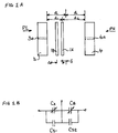
- Figure 1(A) shows the arrangement of the electrodes
- Figure 1(B) shows the electrical circuit.
- diaphragm 1 (1A, 1B) indicates a diaphragm (movable electrode) at different displacement positions.
- Fixed electrodes 3, 4 are arranged on either side of diaphragm 1 so that they are parallel to the surface of diaphragm 1.
- PL and PH indicate the low (negative) and high (positive) pressure applied to the left and right surfaces of diaphragm 1 via small holes 3a and 4a arranged on fixed electrodes 3, 4.
- Distance 2d indicates the distance between the fixed electrodes 3, 4.
- the areas of electrodes 1, 3 and 4 are all substantially equal.
- ⁇ indicates a displacement of diaphragm 1 from the centre point between fixed electrodes 3 and 4.
- ⁇ d is the displacement of diaphragm 1.
- capacitance CA is the part of total capacitance C1 between diaphragm 1 and fixed electrode 3 that changes according to the displacement of diaphragm 1.
- floating capacitance CS1 is the part of capacitance C1 that does not change according to the displacement of diaphragm 1.
- Capacitance CB is the part of total capacitance C2 between diaphragm 1 and fixed electrode 4 that changes according to the displacement of diaphragm 1.
- Floating capacitance CS2 is the part of capacitance C2 that does not change according to the displacement of diaphragm 1.
- This equation makes it possible to determine a very small displacement ⁇ d of the diaphragm, and thus determine pressure difference P of the two sides of diaphragm 1.
- the object of the present invention is to provide a method for measuring pressure difference and a device for converting displacement that solves the above problems.
- the present invention provides a method for measuring pressure difference by detecting a very small movement ⁇ d of a diaphragm (e.g. diaphragm 1) caused by a pressure difference P, as a change in capacitance in a pair of capacitors formed by the diaphragm and two fixed electrodes (e.g. fixed electrodes 3, 4) on either side of and facing the diaphragm.
- a diaphragm e.g. diaphragm 1
- P a very small movement ⁇ d of a diaphragm
- two fixed electrodes e.g. fixed electrodes 3, 4
- a means for measuring capacity (time constant measuring unit 202, A/D converter 203, time counter 206, and the like) is arranged to measure capacitances C1, C2 of the pair of capacitors.
- capacitances C1(P) and C2(P) for a plurality of known pressure difference P measurement points in the positive and/or negative range of pressure difference P are used to calculate constants ⁇ , ⁇ , f(0) and KP from operations (1) and (2).
- capacitances C1(P) and C2(P) and the constant calculated during the preliminary calibration above are used in operations (1) and (2) to calculate measured pressure difference P.
- a second aspect of the invention provides a system for converting displacement by determining the very small displacement ⁇ d of a diaphragm (e.g. diaphragm 1) caused by pressure difference P from the differential change in capacitance in the pair of capacitors formed by the diaphragm and the two fixed electrodes (e.g. electrodes 3, 4) arranged one on either side of the diaphragm.
- a diaphragm e.g. diaphragm 1
- the two fixed electrodes e.g. electrodes 3, 4
- the system comprises: capacitance-measuring means (time constant measuring unit 202, A/D converter 203, timer counter 206, and the like) for measuring the capacitances C1 and C2 of the pair of capacitors noted above; first constant-calculating means (microprocessor 205, external communicator 212 or the like) for calculating two constants ⁇ and ⁇ , based on the floating capacitance of capacitances C1, C2 where f(P) of operation (1) for a plurality of pressure differences measurement points P in the negative and/or positive range of P fulfil linear conditions with respect to pressure difference P.
- the calculation uses capacitances C1, C2 of the pair of capacitors measured during preliminary calibration by capacitance-measuring means for a known pressure difference P in C1(P), C2(P) of operation (1).
- second constant-calculating means (microprocessor 205 or the like) calculating constants KP and f(0).
- F(P) of operation (1) is derived for each pressure difference P using the constants ⁇ and ⁇ calculated using first constant-calculating means, and C1(P), C2(P), measured during preliminary calibration for a known plurality of pressure differences P.
- second constant-calculating means calculates the following two elements in operation (2) that determines linearity: proportional constant KP for the positive and/or the negative range of pressure difference P, as well as constant f(0) corresponding to function f(P) when pressure difference P is 0.
- the capacitance-measuring means determines the capacitances of the pair of capacitors by measuring the difference and the sum of the capacitances.
- the device for converting displacement of claim 4 comprises the device for converting displacement described in claim 2 wherein one of the capacitances is measured, and either the difference or the sum of the two capacitances is measured, and the capacitance of the other capacitor is determined.
- the device may further comprise temperature-detecting means (temperature-detecting means 214 or the like) wherein means for calculating (microprocessor 205 or the like) calculates constants ⁇ , ⁇ corresponding to the temperature detected by temperature-detecting means during pressure difference measurement using constants ⁇ , ⁇ calculated by said first constant-calculating means using the calibration by temperature for a plurality of temperatures detected by temperature-detecting means.
- the resulting constants are used by pressure-difference measuring means to calculate f(P).
- the device may further include temperature-detecting means (means for detecting temperature 214 or the like) and constant-calculating means f(0), KP (microprocessor 205 or the like) corresponding to the temperature detected by pressure-difference measuring means during pressure difference measurement using constants f(0), KP calculated by a second constant-calculating means based on the calibration by temperature for a plurality of temperatures detected by temperature-detecting means. The resulting constants are used by the pressure-difference measuring means for calculating pressure difference P.
- temperature-detecting means means for detecting temperature 214 or the like
- constant-calculating means f(0), KP microprocessor 205 or the like
- the device may further comprise temperature-detecting means (temperature-detecting means 214 or the like); means for calculating the constants ⁇ and ⁇ (microprocessor 205 or the like) corresponding to the temperature determined by temperature-detecting means during pressure difference measurement using constants ⁇ and ⁇ calculated by the first constant-calculating means based on the calibration by temperature of a plurality of temperatures detected by the temperature-detecting means; and constant-calculating means f(0), KP (microprocessor 205 or the like) corresponding to the temperature detected by the temperature-detecting means during pressure difference measurement using constants f(0), KP calculated by second constant-calculating means based on the calibration by temperature for a plurality of temperatures detected by temperature-detecting means.
- the resulting constants are used by the pressure-difference measuring means to calculate measured pressure difference P.
- All elements of the device may be assembled as an integral device (displacement converter 200 or the like); and such a device may use the constants ⁇ and ⁇ calculated by the first constant-calculating means.
- Pressure difference is measured according to the following method. Instead of using a hardware method for compensating the floating capacitances contained in capacitances C1 and C2 from the sensor capacitor, the floating capacitances are determined by performing an initial calibration in which sensor capacitor capacitances C1(P), C2(P) are measured for a plurality of known pressure differences P. This is then used to perform compensation on floating capacitance (using software methods) when pressure differences are to be measured.
- Td and Ta are constants corresponding to ⁇ and ⁇ .
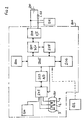
- FIG. 2 is a block diagram of a device for converting displacements according to an embodiment of the present invention.
- this embodiment has a displacement converter 200, a sensor 201 comprising a diaphragm 1 and fixed electrodes 3 and 4 described in Figure 1, a microprocessor 205 serving as an operation control means controlling this displacement converter, a time constant measuring unit 202 measuring capacitances C1, C2 of the sensor capacitors between diaphragm 1 and fixed electrodes 3 and 4 respectively.
- An A/D converter 203 performs an A/D conversion of the time constant measured by the time constant measuring unit 202 and sends the result to the microprocessor 205.
- An external DC power supply 210 is located outside the displacement converter 200 and serves as the power supply for generating the current signal noted above.
- External load resistor 211 is for converting the current signal to a voltage signal (for example, in order to convert a 4-20mA signal to 1-5V, a 250 Ohm resistor would be used).
- External communicator 212 is used when displacement converter 200 transmits data externally.
- External pressure measuring unit 231 serves to measure pressure in cases such as when a known pressure or the like is being applied from outside to sensor 201.
- Temperature detector 214 is arranged on displacement converter 200 to perform temperature correction and the like for displacement converter 200.
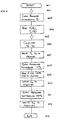
- FIG. 3 shows the operations flow of microprocessor 205 when this embodiment is outputting a linear signal (i.e. in measurement mode with pressure difference P). Steps 301-310 represent steps in this flow.
- microprocessor 205 controls the time constant measuring unit 202, A/D converter 203 and time counter 206 in order to determine times T1 and T2 which are in proportion to capacitances C1 and C2 of the sensor capacitors.
- Times T1 and T2 can be determined by using, for example, the method shown in a previous application by the present applicant (Japanese laid-open publication number 4-257430).
- a sensor capacitor is charged by a prescribed voltage from a power source via a prescribed resistance, and the time it takes for the capacitor to be charged to a prescribed threshold level is measured.
- T1 and T2 instead of determining times T1 and T2, one of the following are determined to obtain T1 and T2: (T1-T2) and (T1+T2); (T1+T2) and T1 or T2; (T1-T2) and T1 or T2.
- step 303 the reference operation noted in operation (17) (shown below) is performed using time constants Td and Ta in memory 204.
- f (T1-T2-Td)/(T1+T2-Ta)
- step 304 constant f(0) (f when pressure difference is 0 percent) in memory 204 is used to determine PN, the difference between f and f(0).
- step 305 KS (the span coefficient) and KZ (the zero coefficient) in memory 204 are used in operation (18) to perform the operations for the output signal for the process handling the pressure difference measurement.
- step 306 the result from this, converter output P out , is sent to D/A converter 207.
- P out KS*PN+KZ
- the calculation in operation (18) provides an output signal P out that is linear to pressure difference P.
- P linear to pressure difference P.
- ZK the signal element sent to D/A converter 207 so that the current signal from V/I converter 209 is 4mA.
- step 307 if there is a read/write request for memory 204 from external communicator 212 (e.g. reading T1, T2, writing Td, Ta, and the like), the read/write operation is performed on memory at step 308.
- external communicator 212 e.g. reading T1, T2, writing Td, Ta, and the like
- FIG. 4 is a flowchart of steps 401-413 indicating the sequence of operations of microprocessor 205 during output adjustment (calibration) of displacement converter 200.
- steps 402-405 data required for the aforementioned constants Td, Ta, which are necessary for linear correction, are retrieved.
- applied pressure difference Px (where X is the parameter representing the number of the measurement point) is sent to sensor 201.
- detected time values T1(Px), T2(Px), which are proportional to capacitances C1, C2 of the sensor capacitors, are read from time measuring unit 202. This operation is repeated for values of X from 0 to n.
- Examples of the types of measurement points include:
- step 404 if displacement conversion takes place by determining the sum and difference of the capacitances C1 and C2 of the sensor capacitors, a read of T1(Px)+T2(Px) and T1(Px)-T2(Px) is performed.
- the displacement conversion takes place by determining either capacitance C1 or C2 and the sum of the capacitances C1 and C2, or by determining either capacitance C1 or C2 and their difference, then a read of T1(Px) or T2(Px) and T1(Px)+T2(Px) is performed, or a read of T1(Px) or T2(Px) and T1(Px)-T2(Px) is performed.
- constants Ta, Td noted above are calculated, and at step 407, the values for Ta and Td are written to memory 204.
- step 406 it would also be possible to perform the calculations of constants Ta and Td outside the displacement converter 200 instead of having the microprocessor 205 perform them. Then, at step 407, the microprocessor 205 would read in the results of the calculations as Ta and Td, and would write these results to memory 204.
- steps 408-410 perform zero-adjustments.
- differential pressure 0% is input.
- the detected time values, T1(0), T2(0) and constants Ta, Td stored in memory 204 are used in operation (17) to determine function f(0). This value is written to memory 204 as a constant.
- P pressure difference
- zero coefficient KZ is set so that converter output P out is set at a desired value (e.g. 4mA), and KZ is written to memory 204.
- step 411 span adjustment is performed.
- a differential pressure of 100% is entered.
- step 412 the coefficient is written to memory 204.
- FIG. 5 is a flowchart indicating the operations of microprocessor 205 when displacement converter 200 is outputting linear converter output P out , which has been temperature-corrected. Steps 501-514 indicate this process.
- microprocessor 205 controls time constant measuring unit 202, A/D converter 203 and timer counter 206. Also, time values T1, T2 proportional to capacitances C1 and C2 of the sensor 201 capacitors are determined.
- temperature TT is measured with temperature detector 214.
- constants Td and Ta that correspond to the current temperature TT are determined using a data table previously stored in memory 204. This data table contains constants Tdi and Tai for temperatures TTi (the "i" in TTi, Tdi and Tai is a parameter indicating the temperature range of TT, Td and Ta).
- FIG. 7 shows an example of the operations procedure for temperature correction. Steps 701-706 perform this procedure.
- Temperature correction values Td' and Ta' which approximate constants Td and Ta, are determined by performing linear approximations between temperatures TT3-TT2 or temperatures TT2-TT1 (steps 703, 704) depending on whether measured temperature TT is greater or less than measured temperature TT2 (step 702).
- step 505 detected time values T1, T2 and constants Td' and Ta', obtained from step 504, are used to determine function f.
- step 507 constant f(0) (the f value when differential pressure is 0%), previously stored in memory by temperature, is used to determine f(0)' as a value for constant f(0) corresponding to the current measured temperature TT.
- step 507 temperature correction for the zero point is performed by setting PN to the difference between f and f'(0).
- step 508 operation (23) below is used to perform temperature correction on the span corresponding to the PN value.
- PN' PN*PN100(TT1)/[(PN100(TT2)-PN100(TT1))(TT-TT1)/(TT2-TT1)+PN100(TT1)]
- PN100(TT1) and PN100(TT2) are values of PN when input is 100% at temperatures TT1 and TT2, which were previously set.
- Temperature TT1 is the temperature for which adjustments to zero coefficient KZ and span coefficient KS are performed (this is called the reference temperature).
- step 509 temperature-corrected converter output P out is determined using operation (24) below.
- step 510 the resulting P out is sent to D/A converter 207.
- P out KS*PN'-KZ
- step 512 performs a read/write operation (e.g. a read of T1, T2, a write of Td, Ta).
- a read/write operation e.g. a read of T1, T2, a write of Td, Ta.
- FIG. 6 is a flowchart indicating an embodiment of the operations performed by microprocessor 205 when the output from displacement converter 200 is adjusted (calibrated) so that temperature correction is possible. Steps 601-620 perform this operation.
- temperature TTi is changed to a number of preset temperature points within a certain range (the "i" in TTi is a parameter indicating the number of the point). For each case (i.e. for each temperature point), a constant is determined according to the procedure in Figure 6 and stored.
- steps 602-605 collect the data necessary for calculating the linear correction constants Tdi and Tai.
- step 606 the linear correction constants Tdi and Tai for that temperature are calculated.
- the operation in steps 602-606 above are identical to steps 402-406 in Figure 4.
- step 607 current temperature data TTi is measured using temperature detector 214.
- step 608 Tdi, Tai and TTi are written to memory 204.
- step 609 assuming the input pressure difference to be 0%, f(0) is measured and is written to memory 204 at step 610.
- step 612 zero coefficient KZ is written to memory 204 only if the temperature is the reference temperature (step 611, branch Y).
- step 614 the input pressure difference is set to 100%, If the temperature is the reference temperature (step 615, branch Y), span coefficient KS is written to memory 204 at step 616. Meanwhile, if the temperature is not the reference temperature (step 615, branch N), PN100i is calculated as the PN value in this case at step 617. At step 618, PN100i is written to memory 204.
- the present invention performs the above corrections for predetermined temperature points beforehand, stores constants for each of these temperature points, measures the temperature as well as the sensor capacitor capacitance values when the pressure difference is measured, and uses the temperature-corrected constant to calculate and output the pressure difference.
- This provides a displacement converter having good linear, zero and span temperature properties.
Landscapes
- Physics & Mathematics (AREA)
- General Physics & Mathematics (AREA)
- Measuring Fluid Pressure (AREA)
- Transmission And Conversion Of Sensor Element Output (AREA)
Applications Claiming Priority (2)
| Application Number | Priority Date | Filing Date | Title |
|---|---|---|---|
| JP05256198A JP3106805B2 (ja) | 1993-10-14 | 1993-10-14 | 圧力差測定方法及び変位変換装置 |
| JP256198/93 | 1993-10-14 |
Publications (3)
| Publication Number | Publication Date |
|---|---|
| EP0649010A2 true EP0649010A2 (de) | 1995-04-19 |
| EP0649010A3 EP0649010A3 (de) | 1996-10-02 |
| EP0649010B1 EP0649010B1 (de) | 1999-03-24 |
Family
ID=17289279
Family Applications (1)
| Application Number | Title | Priority Date | Filing Date |
|---|---|---|---|
| EP94307476A Expired - Lifetime EP0649010B1 (de) | 1993-10-14 | 1994-10-12 | Druckdifferenzmessverfahren und Verschiebungs-Umwandlungsvorrichtung |
Country Status (4)
| Country | Link |
|---|---|
| US (1) | US5598356A (de) |
| EP (1) | EP0649010B1 (de) |
| JP (1) | JP3106805B2 (de) |
| DE (1) | DE69417337T2 (de) |
Cited By (20)
| Publication number | Priority date | Publication date | Assignee | Title |
|---|---|---|---|---|
| WO2009155298A1 (en) * | 2008-06-18 | 2009-12-23 | Qualcomm Mems Technologies, Inc. | Pressure measurement using a mems device |
| US7787171B2 (en) | 2008-03-31 | 2010-08-31 | Qualcomm Mems Technologies, Inc. | Human-readable, bi-state environmental sensors based on micro-mechanical membranes |
| US7787130B2 (en) | 2008-03-31 | 2010-08-31 | Qualcomm Mems Technologies, Inc. | Human-readable, bi-state environmental sensors based on micro-mechanical membranes |
| US7852491B2 (en) | 2008-03-31 | 2010-12-14 | Qualcomm Mems Technologies, Inc. | Human-readable, bi-state environmental sensors based on micro-mechanical membranes |
| US7852483B2 (en) | 2004-09-27 | 2010-12-14 | Qualcomm Mems Technologies, Inc. | Method and system for sensing light using an interferometric element having a coupled temperature sensor |
| US7881686B2 (en) | 2004-09-27 | 2011-02-01 | Qualcomm Mems Technologies, Inc. | Selectable Capacitance Circuit |
| US7929196B2 (en) | 2004-09-27 | 2011-04-19 | Qualcomm Mems Technologies, Inc. | System and method of implementation of interferometric modulators for display mirrors |
| US7944601B2 (en) | 2004-09-27 | 2011-05-17 | Qualcomm Mems Technologies, Inc. | Display device |
| US7969641B2 (en) | 2008-02-14 | 2011-06-28 | Qualcomm Mems Technologies, Inc. | Device having power generating black mask and method of fabricating the same |
| US8004514B2 (en) | 2006-02-10 | 2011-08-23 | Qualcomm Mems Technologies, Inc. | Method and system for updating of displays showing deterministic content |
| US8023169B2 (en) | 2008-03-28 | 2011-09-20 | Qualcomm Mems Technologies, Inc. | Apparatus and method of dual-mode display |
| US8094363B2 (en) | 2007-07-05 | 2012-01-10 | Qualcomm Mems Technologies, Inc. | Integrated imods and solar cells on a substrate |
| US8094358B2 (en) | 2008-03-27 | 2012-01-10 | Qualcomm Mems Technologies, Inc. | Dimming mirror |
| US8340615B2 (en) | 2004-09-27 | 2012-12-25 | Qualcomm Mems Technologies, Inc. | Selectable capacitance circuit |
| US8390916B2 (en) | 2010-06-29 | 2013-03-05 | Qualcomm Mems Technologies, Inc. | System and method for false-color sensing and display |
| CN102980715A (zh) * | 2012-11-16 | 2013-03-20 | 上海朝辉压力仪器有限公司 | 电容式压力变送器及压力传感系统 |
| US8441412B2 (en) | 2006-04-17 | 2013-05-14 | Qualcomm Mems Technologies, Inc. | Mode indicator for interferometric modulator displays |
| US8714023B2 (en) | 2011-03-10 | 2014-05-06 | Qualcomm Mems Technologies, Inc. | System and method for detecting surface perturbations |
| US8904867B2 (en) | 2010-11-04 | 2014-12-09 | Qualcomm Mems Technologies, Inc. | Display-integrated optical accelerometer |
| CN107436694A (zh) * | 2016-05-27 | 2017-12-05 | 辛纳普蒂克斯公司 | 具有沿轴的均匀响应的力传感器 |
Families Citing this family (8)
| Publication number | Priority date | Publication date | Assignee | Title |
|---|---|---|---|---|
| US5861582A (en) * | 1996-01-23 | 1999-01-19 | Synapse Technology, Inc. | Patient weighing system |
| US6827649B2 (en) * | 2003-03-12 | 2004-12-07 | American Axle & Manufacturing, Inc. | Universal joint with friction fit and bearing cup retainer |
| US7808703B2 (en) | 2004-09-27 | 2010-10-05 | Qualcomm Mems Technologies, Inc. | System and method for implementation of interferometric modulator displays |
| US7920135B2 (en) | 2004-09-27 | 2011-04-05 | Qualcomm Mems Technologies, Inc. | Method and system for driving a bi-stable display |
| US8077326B1 (en) | 2008-03-31 | 2011-12-13 | Qualcomm Mems Technologies, Inc. | Human-readable, bi-state environmental sensors based on micro-mechanical membranes |
| US8711361B2 (en) | 2009-11-05 | 2014-04-29 | Qualcomm, Incorporated | Methods and devices for detecting and measuring environmental conditions in high performance device packages |
| JP6537433B2 (ja) * | 2015-06-11 | 2019-07-03 | 東京エレクトロン株式会社 | 静電容量測定用のセンサチップ及び同センサチップを備えた測定器 |
| DE102021131071A1 (de) | 2021-11-26 | 2023-06-01 | Vega Grieshaber Kg | Kapazitive Druckmesszelle mit veränderbarem Elektrodenabstand, Verfahren zur Kalibrierung einer kapazitiven Druckmesszelle |
Family Cites Families (11)
| Publication number | Priority date | Publication date | Assignee | Title |
|---|---|---|---|---|
| JPS5066168A (de) * | 1973-10-12 | 1975-06-04 | ||
| US4016764A (en) * | 1976-07-19 | 1977-04-12 | The United States Of America As Represented By The Secretary Of The Navy | Temperature compensated, high resolution pressure transducer based on capacitance change principles |
| US4092696A (en) * | 1976-12-27 | 1978-05-30 | Borg-Warner Corporation | Variable area capacitive pressure transducer with temperature compensation |
| JPS5928845B2 (ja) * | 1978-08-17 | 1984-07-16 | 富士電機株式会社 | 変位変換装置 |
| US4389646A (en) * | 1980-04-30 | 1983-06-21 | Fuji Electric Co. Ltd. | Displacement converting circuit arrangement |
| US4555952A (en) * | 1984-06-08 | 1985-12-03 | Borg-Warner Corporation | Differential pressure sensor |
| JPS6165114A (ja) * | 1984-09-06 | 1986-04-03 | Yokogawa Hokushin Electric Corp | 容量式変換装置 |
| JP2570420B2 (ja) * | 1988-06-23 | 1997-01-08 | 富士電機株式会社 | 静電容量式圧力検出器 |
| DE3832568A1 (de) * | 1988-09-24 | 1990-03-29 | Philips Patentverwaltung | Schaltungsanordnung zur temperaturkompensation von kapazitiven druck- und differenzdrucksensoren |
| JPH0749968B2 (ja) * | 1988-10-31 | 1995-05-31 | 富士電機株式会社 | 変位変換器 |
| US5163326A (en) | 1991-03-08 | 1992-11-17 | Rosemount Inc. | Line pressure compensator for a pressure transducer |
-
1993
- 1993-10-14 JP JP05256198A patent/JP3106805B2/ja not_active Expired - Fee Related
-
1994
- 1994-10-12 DE DE69417337T patent/DE69417337T2/de not_active Expired - Lifetime
- 1994-10-12 EP EP94307476A patent/EP0649010B1/de not_active Expired - Lifetime
- 1994-10-14 US US08/322,999 patent/US5598356A/en not_active Expired - Lifetime
Cited By (25)
| Publication number | Priority date | Publication date | Assignee | Title |
|---|---|---|---|---|
| US8078128B2 (en) | 2004-09-27 | 2011-12-13 | Qualcomm Mems Technologies, Inc. | Selectable capacitance circuit |
| US8885244B2 (en) | 2004-09-27 | 2014-11-11 | Qualcomm Mems Technologies, Inc. | Display device |
| US8358459B2 (en) | 2004-09-27 | 2013-01-22 | Qualcomm Mems Technologies, Inc. | Display |
| US8340615B2 (en) | 2004-09-27 | 2012-12-25 | Qualcomm Mems Technologies, Inc. | Selectable capacitance circuit |
| US7852483B2 (en) | 2004-09-27 | 2010-12-14 | Qualcomm Mems Technologies, Inc. | Method and system for sensing light using an interferometric element having a coupled temperature sensor |
| US7944601B2 (en) | 2004-09-27 | 2011-05-17 | Qualcomm Mems Technologies, Inc. | Display device |
| US7881686B2 (en) | 2004-09-27 | 2011-02-01 | Qualcomm Mems Technologies, Inc. | Selectable Capacitance Circuit |
| US7929196B2 (en) | 2004-09-27 | 2011-04-19 | Qualcomm Mems Technologies, Inc. | System and method of implementation of interferometric modulators for display mirrors |
| US8004514B2 (en) | 2006-02-10 | 2011-08-23 | Qualcomm Mems Technologies, Inc. | Method and system for updating of displays showing deterministic content |
| US8441412B2 (en) | 2006-04-17 | 2013-05-14 | Qualcomm Mems Technologies, Inc. | Mode indicator for interferometric modulator displays |
| US8094363B2 (en) | 2007-07-05 | 2012-01-10 | Qualcomm Mems Technologies, Inc. | Integrated imods and solar cells on a substrate |
| US7969641B2 (en) | 2008-02-14 | 2011-06-28 | Qualcomm Mems Technologies, Inc. | Device having power generating black mask and method of fabricating the same |
| US8094358B2 (en) | 2008-03-27 | 2012-01-10 | Qualcomm Mems Technologies, Inc. | Dimming mirror |
| US8023169B2 (en) | 2008-03-28 | 2011-09-20 | Qualcomm Mems Technologies, Inc. | Apparatus and method of dual-mode display |
| US7787171B2 (en) | 2008-03-31 | 2010-08-31 | Qualcomm Mems Technologies, Inc. | Human-readable, bi-state environmental sensors based on micro-mechanical membranes |
| US7852491B2 (en) | 2008-03-31 | 2010-12-14 | Qualcomm Mems Technologies, Inc. | Human-readable, bi-state environmental sensors based on micro-mechanical membranes |
| US7787130B2 (en) | 2008-03-31 | 2010-08-31 | Qualcomm Mems Technologies, Inc. | Human-readable, bi-state environmental sensors based on micro-mechanical membranes |
| WO2009155298A1 (en) * | 2008-06-18 | 2009-12-23 | Qualcomm Mems Technologies, Inc. | Pressure measurement using a mems device |
| US7860668B2 (en) | 2008-06-18 | 2010-12-28 | Qualcomm Mems Technologies, Inc. | Pressure measurement using a MEMS device |
| US8390916B2 (en) | 2010-06-29 | 2013-03-05 | Qualcomm Mems Technologies, Inc. | System and method for false-color sensing and display |
| US8904867B2 (en) | 2010-11-04 | 2014-12-09 | Qualcomm Mems Technologies, Inc. | Display-integrated optical accelerometer |
| US8714023B2 (en) | 2011-03-10 | 2014-05-06 | Qualcomm Mems Technologies, Inc. | System and method for detecting surface perturbations |
| CN102980715A (zh) * | 2012-11-16 | 2013-03-20 | 上海朝辉压力仪器有限公司 | 电容式压力变送器及压力传感系统 |
| CN102980715B (zh) * | 2012-11-16 | 2015-12-30 | 上海朝辉压力仪器有限公司 | 电容式压力变送器及压力传感系统 |
| CN107436694A (zh) * | 2016-05-27 | 2017-12-05 | 辛纳普蒂克斯公司 | 具有沿轴的均匀响应的力传感器 |
Also Published As
| Publication number | Publication date |
|---|---|
| DE69417337D1 (de) | 1999-04-29 |
| EP0649010A3 (de) | 1996-10-02 |
| JP3106805B2 (ja) | 2000-11-06 |
| US5598356A (en) | 1997-01-28 |
| DE69417337T2 (de) | 1999-07-22 |
| EP0649010B1 (de) | 1999-03-24 |
| JPH07113709A (ja) | 1995-05-02 |
Similar Documents
| Publication | Publication Date | Title |
|---|---|---|
| EP0649010B1 (de) | Druckdifferenzmessverfahren und Verschiebungs-Umwandlungsvorrichtung | |
| RU2138781C1 (ru) | Датчик с улучшенной компенсацией | |
| US5329818A (en) | Correction of a pressure indication in a pressure transducer due to variations of an environmental condition | |
| US4437164A (en) | Ridge circuit compensation for environmental effects | |
| US4322977A (en) | Pressure measuring system | |
| EP0803054B1 (de) | Methode zur temperaturkompensation für druckwandler | |
| US4357834A (en) | Displacement converter | |
| EP0812414B1 (de) | Druckübertrager mit entfernter trennmembran und korrektur der temperatur sowie höhe ( auch membransteifheit ) | |
| JPH0697169B2 (ja) | センサ信号の温度補償方法 | |
| CN1348541A (zh) | 用于校正传感器漂移的设备和方法 | |
| US4282480A (en) | Apparatus for humidity detection | |
| WO1986002487A1 (en) | Circuit for capacitive sensor made of brittle material | |
| US4490803A (en) | Temperature compensation of a resistance bridge circuit | |
| EP0574539B1 (de) | Kompensator des statischen drucks für druckwandler | |
| JP2579143B2 (ja) | プロセス変数センサのディジタル補正の方法およびそのためのプロセス変数発信器 | |
| US5656784A (en) | Fluid density variation compensation for fluid flow volume measurement | |
| RU2108556C1 (ru) | Способ и устройство для емкостной температурной компенсации и двухпластинчатый емкостной преобразователь давления для его реализации | |
| JP4525222B2 (ja) | 静電容量式圧力測定装置 | |
| JP4325117B2 (ja) | 静電容量式圧力測定装置 | |
| CN1177398A (zh) | 带遥控密封膜片及其校正电路的压力变送器 | |
| JPS6245485B2 (de) | ||
| CA2210243A1 (en) | Pressure transmitter with remote seal diaphragm and correction circuit therefor |
Legal Events
| Date | Code | Title | Description |
|---|---|---|---|
| PUAI | Public reference made under article 153(3) epc to a published international application that has entered the european phase |
Free format text: ORIGINAL CODE: 0009012 |
|
| AK | Designated contracting states |
Kind code of ref document: A2 Designated state(s): DE FR GB IT |
|
| PUAL | Search report despatched |
Free format text: ORIGINAL CODE: 0009013 |
|
| AK | Designated contracting states |
Kind code of ref document: A3 Designated state(s): DE FR GB IT |
|
| 17P | Request for examination filed |
Effective date: 19961126 |
|
| 17Q | First examination report despatched |
Effective date: 19971002 |
|
| GRAG | Despatch of communication of intention to grant |
Free format text: ORIGINAL CODE: EPIDOS AGRA |
|
| GRAG | Despatch of communication of intention to grant |
Free format text: ORIGINAL CODE: EPIDOS AGRA |
|
| GRAH | Despatch of communication of intention to grant a patent |
Free format text: ORIGINAL CODE: EPIDOS IGRA |
|
| GRAH | Despatch of communication of intention to grant a patent |
Free format text: ORIGINAL CODE: EPIDOS IGRA |
|
| GRAA | (expected) grant |
Free format text: ORIGINAL CODE: 0009210 |
|
| AK | Designated contracting states |
Kind code of ref document: B1 Designated state(s): DE FR GB IT |
|
| ITF | It: translation for a ep patent filed | ||
| REF | Corresponds to: |
Ref document number: 69417337 Country of ref document: DE Date of ref document: 19990429 |
|
| ET | Fr: translation filed | ||
| PLBE | No opposition filed within time limit |
Free format text: ORIGINAL CODE: 0009261 |
|
| STAA | Information on the status of an ep patent application or granted ep patent |
Free format text: STATUS: NO OPPOSITION FILED WITHIN TIME LIMIT |
|
| 26N | No opposition filed | ||
| REG | Reference to a national code |
Ref country code: GB Ref legal event code: IF02 |
|
| PGFP | Annual fee paid to national office [announced via postgrant information from national office to epo] |
Ref country code: DE Payment date: 20101006 Year of fee payment: 17 |
|
| PGFP | Annual fee paid to national office [announced via postgrant information from national office to epo] |
Ref country code: IT Payment date: 20101020 Year of fee payment: 17 |
|
| PG25 | Lapsed in a contracting state [announced via postgrant information from national office to epo] |
Ref country code: DE Free format text: LAPSE BECAUSE OF NON-PAYMENT OF DUE FEES Effective date: 20120501 |
|
| REG | Reference to a national code |
Ref country code: DE Ref legal event code: R119 Ref document number: 69417337 Country of ref document: DE Effective date: 20120501 |
|
| PG25 | Lapsed in a contracting state [announced via postgrant information from national office to epo] |
Ref country code: IT Free format text: LAPSE BECAUSE OF NON-PAYMENT OF DUE FEES Effective date: 20111012 |
|
| PGFP | Annual fee paid to national office [announced via postgrant information from national office to epo] |
Ref country code: FR Payment date: 20131009 Year of fee payment: 20 Ref country code: GB Payment date: 20131009 Year of fee payment: 20 |
|
| REG | Reference to a national code |
Ref country code: GB Ref legal event code: PE20 Expiry date: 20141011 |
|
| PG25 | Lapsed in a contracting state [announced via postgrant information from national office to epo] |
Ref country code: GB Free format text: LAPSE BECAUSE OF EXPIRATION OF PROTECTION Effective date: 20141011 |