EP0648317B1 - Serie de blocs d'engrenage - Google Patents
Serie de blocs d'engrenage Download PDFInfo
- Publication number
- EP0648317B1 EP0648317B1 EP93915725A EP93915725A EP0648317B1 EP 0648317 B1 EP0648317 B1 EP 0648317B1 EP 93915725 A EP93915725 A EP 93915725A EP 93915725 A EP93915725 A EP 93915725A EP 0648317 B1 EP0648317 B1 EP 0648317B1
- Authority
- EP
- European Patent Office
- Prior art keywords
- gear
- stage
- series
- gear units
- stepped
- Prior art date
- Legal status (The legal status is an assumption and is not a legal conclusion. Google has not performed a legal analysis and makes no representation as to the accuracy of the status listed.)
- Expired - Lifetime
Links
- 238000000034 method Methods 0.000 description 6
- 238000004519 manufacturing process Methods 0.000 description 4
- 238000011161 development Methods 0.000 description 3
- 230000018109 developmental process Effects 0.000 description 3
- 238000003754 machining Methods 0.000 description 3
- 230000002411 adverse Effects 0.000 description 1
- 230000000712 assembly Effects 0.000 description 1
- 238000000429 assembly Methods 0.000 description 1
- 238000010923 batch production Methods 0.000 description 1
- 230000002860 competitive effect Effects 0.000 description 1
- 230000008878 coupling Effects 0.000 description 1
- 238000010168 coupling process Methods 0.000 description 1
- 238000005859 coupling reaction Methods 0.000 description 1
- 230000001186 cumulative effect Effects 0.000 description 1
- 238000005516 engineering process Methods 0.000 description 1
Images

Classifications
-
- F—MECHANICAL ENGINEERING; LIGHTING; HEATING; WEAPONS; BLASTING
- F16—ENGINEERING ELEMENTS AND UNITS; GENERAL MEASURES FOR PRODUCING AND MAINTAINING EFFECTIVE FUNCTIONING OF MACHINES OR INSTALLATIONS; THERMAL INSULATION IN GENERAL
- F16H—GEARING
- F16H57/00—General details of gearing
- F16H57/02—Gearboxes; Mounting gearing therein
- F16H57/033—Series gearboxes, e.g. gearboxes based on the same design being available in different sizes or gearboxes using a combination of several standardised units
-
- F—MECHANICAL ENGINEERING; LIGHTING; HEATING; WEAPONS; BLASTING
- F16—ENGINEERING ELEMENTS AND UNITS; GENERAL MEASURES FOR PRODUCING AND MAINTAINING EFFECTIVE FUNCTIONING OF MACHINES OR INSTALLATIONS; THERMAL INSULATION IN GENERAL
- F16H—GEARING
- F16H57/00—General details of gearing
- F16H57/02—Gearboxes; Mounting gearing therein
- F16H57/038—Gearboxes for accommodating bevel gears
-
- F—MECHANICAL ENGINEERING; LIGHTING; HEATING; WEAPONS; BLASTING
- F16—ENGINEERING ELEMENTS AND UNITS; GENERAL MEASURES FOR PRODUCING AND MAINTAINING EFFECTIVE FUNCTIONING OF MACHINES OR INSTALLATIONS; THERMAL INSULATION IN GENERAL
- F16H—GEARING
- F16H1/00—Toothed gearings for conveying rotary motion
- F16H1/02—Toothed gearings for conveying rotary motion without gears having orbital motion
- F16H1/20—Toothed gearings for conveying rotary motion without gears having orbital motion involving more than two intermeshing members
- F16H1/203—Toothed gearings for conveying rotary motion without gears having orbital motion involving more than two intermeshing members with non-parallel axes
-
- F—MECHANICAL ENGINEERING; LIGHTING; HEATING; WEAPONS; BLASTING
- F16—ENGINEERING ELEMENTS AND UNITS; GENERAL MEASURES FOR PRODUCING AND MAINTAINING EFFECTIVE FUNCTIONING OF MACHINES OR INSTALLATIONS; THERMAL INSULATION IN GENERAL
- F16H—GEARING
- F16H57/00—General details of gearing
- F16H57/02—Gearboxes; Mounting gearing therein
- F16H57/033—Series gearboxes, e.g. gearboxes based on the same design being available in different sizes or gearboxes using a combination of several standardised units
- F16H2057/0335—Series transmissions of modular design, e.g. providing for different transmission ratios or power ranges
Definitions
- This invention relates to a series of gear units of the kind in which the series includes gear units of two or more stages and includes gear units providing a range of different torques and ratios. It relates also, but not exclusively, to a series which may include a variety of input and/or output shaft configurations.
- Custom built gear units can be provided for all kinds of applications, this with a certain development and production cost.
- the number of variables such as torque, rotating speed, total ratio, number of stages, low speed shaft inclination and option of parallel or right angle shafts hampers the economic production of custom built gear units.
- GB Patent GB-A-673190 showed how the components can be standardised starting from a series of centre distances, which allows eg to use a gear set used as a given stage in one size gear unit, as another stage in another size.
- Another example of standardisation of components starting from a series of centre distances is disclosed by US-A-3029661.
- GB Patent GB-A-1338610 shows how such an optimisation procedure combines internal economy of the series with high market adequacy.
- the present invention seeks to provide a series of gear units incorporating an improved standardisation procedure in which problems associated with known standardisation procedures are mitigated or overcome and which at least in part allows advantageous utilisation of technical developments that affect the design and/or capability of component parts of gear units.
- each gear unit comprises two or more stages with standardised shaft centre distances and standardised gear wheels where for any stage of given centre distance and gear ratio the same intermediate pinion shaft as hereinafter defined is used systematically in a non-stepped two stage housing and stepped three stage housings which are stepped symmetrically about a plane which extends transversely relative to said pinion shaft.
- pinion shaft is used herein in relation to the present invention to refer to a shaft having a pinion formed integrally therewith.
- stepped housing refers to a housing in which those parts of the housing, referred to as “bearing blocks”, which support the gear shaft bearings are stepped, i e non-planar, at their inner and outer faces.
- a “non-stepped housing” is a housing having bearing blocks which are substantially planar at their inner and outer surfaces such that the pair of bearings provided in the respective bearing blocks to support a shaft are spaced in the direction of the length of the shaft by substantially the same distance for each shaft of the gear unit which extends between those blocks.
- the series of gear units is further characterised by the feature that for any high speed stage of given centre distance and gear ratio the same high speed pinion shaft is used systematically in a non-stepped two stage housing and at least one symmetrically stepped three stage housing.
- the high speed pinion shaft may be of either a single or double extension type, that is it may extend externally of the housing through only one or through both of the bearing blocks.
- the series of gear units may comprise pairs of gear units having opposite handing of the shaft extension of at least one of the input and output shafts.
- the oppositely handed gear units may be gear units of the same size, using the same housing and the internals of one gear unit may be mounted in a manner which is reversed compared with that of the other gear unit so as to provide said opposite handing.
- the series of gear units may comprise gear units in which the high speed gear stage is either a standardised cylindrical or standardised bevel gear set.
- the gear units may comprise housings of a kind adapted to receive and locate a high speed gear stage which is either of a cylindrical or a bevel gear set type.
- Each bearing block of a gear unit preferably comprises at least a part which extends continuously (i e is not split) between the parallel axes of successive shafts such that said part may serve to dictate the spacing of said shafts.
- a two stage gear unit 10 comprises a housing having a pair of non-stepped bearing blocks 11.
- the blocks 11 are fitted with conventional bearings (not shown) rotatably to support a high speed pinion shaft 12 having a single extension 13, an intermediate pinion shaft 14 which carries a wheel 12' that intermeshes with the pinion shaft 12 and an output shaft 15 having a pair of external extensions 16 and which carries a wheel 14' that intermeshes with the intermediate pinion shaft 14.
- the shaft 15 alternatively may have only a single extension).
- centre distances 'c' and 'e' are selected from a standardised series of increasing centre distances a, c, e, g, ising .
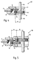
- Figure 3 shows a gear unit 30 of a size larger than that of Figure 1 and having three stages.
- the three stages have centre distances 'c', 'e' and 'g'.
- the high speed stage and intermediate stage have respectively the same centre distances 'c' and 'e' as the corresponding high speed and low speed stages of the two stage gear unit of a smaller size in Figure 1 and therefore utilise the same shafts 12 and 14 and wheels 12' and 14'.
- the housing blocks 32 of Figure 3 are each of a stepped type, symmetrically arranged, and the shafts 12 and 14 are both located in the narrower region of the housing.
- the high speed pinion shaft 12 is spaced from the step 33 in each housing block by at least the high speed stage centre distance 'c' so that the external extension 13 (or each extension if the shaft were of the double extension type) is readily available for use over its whole length without interference from the step(s) 33.
- a three stage gear unit 18 (see Figure 2) of the same size as the gear unit shown in Figure 1 the same wheel 12', pinion shaft 14, wheel 14' and output shaft 15 are employed for the stages having the corresponding centre distances 'c' and 'e'.
- the gear unit has a housing 17.
- the high speed pinion shaft 20 and the intermediate pinion shaft 21 with wheel 20' are additional components and can be utilised for example in a two stage gear unit of a smaller size as is apparent from the previous description of Figure 3 and comparison thereof with Figure 1.
- a high speed bevel gear input pinion shaft or shaft with pinion 7, mounting block 6, bevel wheel 8 first intermediate pinion shaft 14 and wheel 14' are common to both a two stage gear unit of a first size (size E) and a three stage gear unit of a second, larger size (size G).
- the present invention therefore provides high speed and intermediate pinion shafts of adequate stiffness and which are systematically standardised.
- the invention achieves this in a manner which also allows the provision of bevel gear set assemblies in the same housings and the selective reversal of shaft extensions, in each case the standardised high speed shaft of a three stage gear unit being spaced from the step in the housing so that there is good accessibility for example for coupling devices.
Landscapes
- Engineering & Computer Science (AREA)
- General Engineering & Computer Science (AREA)
- Mechanical Engineering (AREA)
- Gear Transmission (AREA)
- General Details Of Gearings (AREA)
Abstract
Claims (9)
- Série de trains d'engrenages (10, 18, 30, 40, 50) à couple croissant du type dans lequel chaque train d'engrenages comprend au moins deux étages comprenant des entre-axes d'arbres (a, c, e, ...) standardisés et des roues dentées standardisées, caractérisée en ce que pour chaque étage ayant un entre-axes (e) et un rapport d'engrenage donnés, le même arbre à pignon intermédiaire (14) est utilisé systématiquement dans un carter à deux étages sans gradin (11) et dans des carters à trois étages avec gradins (17, 32) dont les gradins sont symétriques par rapport à un plan qui s'étend transversalement audit arbre à pignon (14).
- Série de trains d'engrenages (10, 30) selon la revendication 1, caractérisée en ce que pour chaque étage de vitesse élevée ayant un entre-axes (c) et un rapport d'engrenage donnés, le même arbre à pignon de vitesse élevée (12) est utilisé systématiquement dans un carter à deux étages sans gradin (11) et dans un carter à trois étages avec gradins symétriques (32).
- Série de trains d'engrenages selon la revendication 1 ou la revendication 2, caractérisée en ce que des paires de trains d'engrenages de la série ont une disposition opposée du prolongement de l'un au moins des arbres d'entrée et de sortie.
- Série de trains d'engrenages selon la revendication 3, dans laquelle lesdites paires de trains d'engrenages sont de la même taille et utilisent le même carter, et en ce que les éléments internes de l'un des trains d'engrenages sont montés de manière inversée par rapport à ceux de l'autre train d'engrenages.
- Série de trains d'engrenages selon l'une quelconque des revendications précédentes, caractérisée en ce que l'arbre à pignon de vitesse élevée est du type à deux prolongements.
- Série de trains d'engrenages (10, 30; 40, 50) selon l'une quelconque des revendications précédentes, caractérisée en ce que le même étage intermédiaire ou de vitesse faible (14, 14') peut être combiné soit avec un étage de vitesse élevée à engrenages cylindriques standardisés (12, 12') soit avec un étage de vitesse élevée à engrenages coniques standardisés (7, 8).
- Série de trains d'engrenages selon l'une quelconque des revendications précédentes, caractérisée en ce que certains au moins des trains d'engrenages (10, 30; 40, 50) de la série comprennent des carters (11, 32) d'un type adapté pour recevoir et positionner un étage de vitesse élevée soit du type à engrenages cylindriques soit du type à engrenages coniques.
- Série de trains d'engrenages (40, 50) selon l'une quelconque des revendications précédentes, caractérisée en ce que pour chaque étage d'engrenages coniques de vitesse élevée ayant une taille et un rapport d'engrenage donnés, le même ensemble formant étage d'engrenages coniques (6, 7, 8) est utilisé systématiquement dans un carter à deux étages sans gradin (Il) et dans un carter à trois étages avec gradins symétriques (32).
- Série de trains d'engrenages (10, 18, 30; 40, 50) selon l'une quelconque des revendications précédentes, caractérisée en ce que le carter comprend un bloc de palier (11, 17, 32) dont une partie au moins s'étend d'une manière continue entre des arbres parallèles successifs et contribue à définir l'espacement de ceux-ci.
Priority Applications (1)
| Application Number | Priority Date | Filing Date | Title |
|---|---|---|---|
| EP93915725A EP0648317B1 (fr) | 1992-07-06 | 1993-06-29 | Serie de blocs d'engrenage |
Applications Claiming Priority (4)
| Application Number | Priority Date | Filing Date | Title |
|---|---|---|---|
| EP92306181 | 1992-07-06 | ||
| EP92306181 | 1992-07-06 | ||
| PCT/EP1993/001655 WO1994001700A1 (fr) | 1992-07-06 | 1993-06-29 | Serie de blocs d'engrenage |
| EP93915725A EP0648317B1 (fr) | 1992-07-06 | 1993-06-29 | Serie de blocs d'engrenage |
Publications (2)
| Publication Number | Publication Date |
|---|---|
| EP0648317A1 EP0648317A1 (fr) | 1995-04-19 |
| EP0648317B1 true EP0648317B1 (fr) | 1996-08-14 |
Family
ID=8211425
Family Applications (1)
| Application Number | Title | Priority Date | Filing Date |
|---|---|---|---|
| EP93915725A Expired - Lifetime EP0648317B1 (fr) | 1992-07-06 | 1993-06-29 | Serie de blocs d'engrenage |
Country Status (7)
| Country | Link |
|---|---|
| EP (1) | EP0648317B1 (fr) |
| JP (1) | JP2860164B2 (fr) |
| KR (1) | KR100187555B1 (fr) |
| AU (1) | AU4560493A (fr) |
| DE (1) | DE69304071T2 (fr) |
| FI (1) | FI108074B (fr) |
| WO (1) | WO1994001700A1 (fr) |
Families Citing this family (9)
| Publication number | Priority date | Publication date | Assignee | Title |
|---|---|---|---|---|
| IT1315391B1 (it) * | 2000-02-11 | 2003-02-10 | Antonio Valentini | Gruppo di trasmissione laterale per fresatrici per la lavorazione delterreno. |
| ES2593113T3 (es) * | 2003-08-07 | 2016-12-05 | Allergan, Inc. | Composiciones para el suministro de agentes terapéuticos en los ojos y métodos para obtener y usar los mismos |
| DE102005026657B4 (de) * | 2004-08-17 | 2012-04-12 | Sew-Eurodrive Gmbh & Co. Kg | Gehäuse, Getriebe und Getriebebaukasten |
| DE102005063570B4 (de) * | 2004-08-17 | 2013-09-19 | Sew-Eurodrive Gmbh & Co. Kg | Gehäuse, Getriebe und Getriebebaukasten |
| ATE450728T1 (de) * | 2004-10-08 | 2009-12-15 | Sew Eurodrive Gmbh & Co | Getriebereihe |
| JP2019120294A (ja) | 2017-12-28 | 2019-07-22 | 本田技研工業株式会社 | 駆動装置、部品セット及び組立方法 |
| CN108953537A (zh) * | 2018-08-03 | 2018-12-07 | 东南大学 | 一种模块化级联式变速器 |
| CN110261103B (zh) * | 2019-07-01 | 2020-12-29 | 重庆大学 | 一种基于数控系统的可变中心距齿轮接触疲劳试验台 |
| DE102023110052A1 (de) * | 2023-04-20 | 2024-10-24 | Knorr-Bremse Systeme für Nutzfahrzeuge GmbH | Verfahren zur Herstellung eines Getriebes und ein Getriebe |
Family Cites Families (6)
| Publication number | Priority date | Publication date | Assignee | Title |
|---|---|---|---|---|
| NL76635C (fr) * | 1949-10-31 | |||
| US3029661A (en) | 1959-07-09 | 1962-04-17 | Falk Corp | All purpose speed reducer |
| DE1932624A1 (de) * | 1969-06-27 | 1971-01-07 | Friedhelm Hitpass | Getriebe mit einem aus mehreren Gehaeuseelementen zusammensetzbaren Gehaeuse |
| BE747171A (nl) * | 1970-03-11 | 1970-09-11 | Machinery And Gears Hansen N V | Reeks tandwielreductiekasten, |
| DD290556A7 (de) * | 1989-05-29 | 1991-06-06 | Veb Getriebewerk Penig,De | Getriebegehaeuse fuer mehrstufige getriebereihen im baukastensystem |
| DE4012188A1 (de) * | 1990-04-14 | 1991-10-24 | Sumitomo Heavy Industries | Getriebebaureihe |
-
1993
- 1993-06-29 WO PCT/EP1993/001655 patent/WO1994001700A1/fr not_active Ceased
- 1993-06-29 JP JP6502892A patent/JP2860164B2/ja not_active Expired - Lifetime
- 1993-06-29 DE DE69304071T patent/DE69304071T2/de not_active Expired - Lifetime
- 1993-06-29 AU AU45604/93A patent/AU4560493A/en not_active Abandoned
- 1993-06-29 EP EP93915725A patent/EP0648317B1/fr not_active Expired - Lifetime
- 1993-06-29 KR KR1019950700025A patent/KR100187555B1/ko not_active Expired - Lifetime
-
1995
- 1995-01-02 FI FI950005A patent/FI108074B/fi active
Also Published As
| Publication number | Publication date |
|---|---|
| DE69304071D1 (de) | 1996-09-19 |
| FI950005L (fi) | 1995-02-08 |
| FI950005A0 (fi) | 1995-01-02 |
| EP0648317A1 (fr) | 1995-04-19 |
| WO1994001700A1 (fr) | 1994-01-20 |
| FI108074B (fi) | 2001-11-15 |
| DE69304071T2 (de) | 1996-12-19 |
| KR950702687A (ko) | 1995-07-29 |
| JPH07507861A (ja) | 1995-08-31 |
| JP2860164B2 (ja) | 1999-02-24 |
| KR100187555B1 (ko) | 1999-06-01 |
| AU4560493A (en) | 1994-01-31 |
Similar Documents
| Publication | Publication Date | Title |
|---|---|---|
| US5680793A (en) | Series of gear units | |
| EP0648317B1 (fr) | Serie de blocs d'engrenage | |
| EP1326032B1 (fr) | Serie de moteurs avec reducteur de vitesse | |
| EP2041861B1 (fr) | Engrenage magnetique | |
| EP0687837B1 (fr) | Moto-réducteurs | |
| US6931959B2 (en) | Train housing for pseudo-planetary kinematic transmission | |
| WO1993002300A1 (fr) | Differentiel constitue d'une combinaison d'engrenages a axes paralleles | |
| EP0559626B1 (fr) | Réducteur planétaire | |
| US5220852A (en) | Motor-equipped reduction gear device with a pre-stage | |
| EP0452739B2 (fr) | Série de transmissions | |
| KR100509325B1 (ko) | 하이포이드 감속장치 및 그 그룹 | |
| US6530138B2 (en) | Method for manufacturing a gear reducer | |
| US5376057A (en) | Multistage differential gear package | |
| JP3854346B2 (ja) | ギヤドモータのシリーズ | |
| US20040097319A1 (en) | Method of manufacturing wobbling inner gearing planetary gear system and gear system | |
| JPH06241282A (ja) | 内接噛合遊星歯車構造を採用したギヤドモータ及びそのシリーズ | |
| US5108353A (en) | Crossed-axis gear differential | |
| CN110848332B (zh) | 一种相交轴非圆面齿轮传动机构 | |
| JP4056614B2 (ja) | 平行軸歯車減速機 | |
| US6272941B1 (en) | Gear reducer having symmetrically disposed rotational shaft supports and method for making same | |
| JPH0763243A (ja) | 差動型内接噛合遊星歯車構造 | |
| JP3854345B2 (ja) | 変速機のシリーズ | |
| US5875690A (en) | Multistage angular reducer | |
| JP2002364716A (ja) | 増減速機のシリーズ | |
| JPS6124854A (ja) | 遊星歯車増減速機 |
Legal Events
| Date | Code | Title | Description |
|---|---|---|---|
| PUAI | Public reference made under article 153(3) epc to a published international application that has entered the european phase |
Free format text: ORIGINAL CODE: 0009012 |
|
| 17P | Request for examination filed |
Effective date: 19941227 |
|
| AK | Designated contracting states |
Kind code of ref document: A1 Designated state(s): DE FR GB IT |
|
| GRAG | Despatch of communication of intention to grant |
Free format text: ORIGINAL CODE: EPIDOS AGRA |
|
| GRAH | Despatch of communication of intention to grant a patent |
Free format text: ORIGINAL CODE: EPIDOS IGRA |
|
| 17Q | First examination report despatched |
Effective date: 19951219 |
|
| GRAH | Despatch of communication of intention to grant a patent |
Free format text: ORIGINAL CODE: EPIDOS IGRA |
|
| GRAA | (expected) grant |
Free format text: ORIGINAL CODE: 0009210 |
|
| AK | Designated contracting states |
Kind code of ref document: B1 Designated state(s): DE FR GB IT |
|
| ITF | It: translation for a ep patent filed | ||
| REF | Corresponds to: |
Ref document number: 69304071 Country of ref document: DE Date of ref document: 19960919 |
|
| ET | Fr: translation filed | ||
| PLBE | No opposition filed within time limit |
Free format text: ORIGINAL CODE: 0009261 |
|
| STAA | Information on the status of an ep patent application or granted ep patent |
Free format text: STATUS: NO OPPOSITION FILED WITHIN TIME LIMIT |
|
| 26N | No opposition filed | ||
| ET1 | Fr: translation filed ** revision of the translation of the patent or the claims | ||
| REG | Reference to a national code |
Ref country code: GB Ref legal event code: IF02 |
|
| REG | Reference to a national code |
Ref country code: GB Ref legal event code: 732E Free format text: REGISTERED BETWEEN 20110224 AND 20110302 |
|
| REG | Reference to a national code |
Ref country code: FR Ref legal event code: TP |
|
| REG | Reference to a national code |
Ref country code: DE Ref legal event code: R081 Ref document number: 69304071 Country of ref document: DE Owner name: HANSEN INDUSTRIAL TRANSMISSIONS N.V., BE Free format text: FORMER OWNER: HANSEN TRANSMISSIONS INTERNATIONAL N.V., EDEGEM, BE Effective date: 20110513 |
|
| PGFP | Annual fee paid to national office [announced via postgrant information from national office to epo] |
Ref country code: GB Payment date: 20120627 Year of fee payment: 20 |
|
| PGFP | Annual fee paid to national office [announced via postgrant information from national office to epo] |
Ref country code: IT Payment date: 20120619 Year of fee payment: 20 |
|
| PGFP | Annual fee paid to national office [announced via postgrant information from national office to epo] |
Ref country code: DE Payment date: 20120926 Year of fee payment: 20 |
|
| PGFP | Annual fee paid to national office [announced via postgrant information from national office to epo] |
Ref country code: FR Payment date: 20121030 Year of fee payment: 20 |
|
| REG | Reference to a national code |
Ref country code: DE Ref legal event code: R071 Ref document number: 69304071 Country of ref document: DE |
|
| REG | Reference to a national code |
Ref country code: GB Ref legal event code: PE20 Expiry date: 20130628 |
|
| PG25 | Lapsed in a contracting state [announced via postgrant information from national office to epo] |
Ref country code: GB Free format text: LAPSE BECAUSE OF EXPIRATION OF PROTECTION Effective date: 20130628 |
|
| PG25 | Lapsed in a contracting state [announced via postgrant information from national office to epo] |
Ref country code: DE Free format text: LAPSE BECAUSE OF EXPIRATION OF PROTECTION Effective date: 20130702 |