EP0645529B1 - Maschine mit thermischer Isolation - Google Patents
Maschine mit thermischer Isolation Download PDFInfo
- Publication number
- EP0645529B1 EP0645529B1 EP93307662A EP93307662A EP0645529B1 EP 0645529 B1 EP0645529 B1 EP 0645529B1 EP 93307662 A EP93307662 A EP 93307662A EP 93307662 A EP93307662 A EP 93307662A EP 0645529 B1 EP0645529 B1 EP 0645529B1
- Authority
- EP
- European Patent Office
- Prior art keywords
- thermally insulating
- chamber
- engine according
- air intake
- subcombustion
- Prior art date
- Legal status (The legal status is an assumption and is not a legal conclusion. Google has not performed a legal analysis and makes no representation as to the accuracy of the status listed.)
- Expired - Lifetime
Links
Images


Classifications
-
- F—MECHANICAL ENGINEERING; LIGHTING; HEATING; WEAPONS; BLASTING
- F01—MACHINES OR ENGINES IN GENERAL; ENGINE PLANTS IN GENERAL; STEAM ENGINES
- F01N—GAS-FLOW SILENCERS OR EXHAUST APPARATUS FOR MACHINES OR ENGINES IN GENERAL; GAS-FLOW SILENCERS OR EXHAUST APPARATUS FOR INTERNAL COMBUSTION ENGINES
- F01N13/00—Exhaust or silencing apparatus characterised by constructional features ; Exhaust or silencing apparatus, or parts thereof, having pertinent characteristics not provided for in, or of interest apart from, groups F01N1/00 - F01N5/00, F01N9/00, F01N11/00
- F01N13/08—Other arrangements or adaptations of exhaust conduits
- F01N13/10—Other arrangements or adaptations of exhaust conduits of exhaust manifolds
- F01N13/107—More than one exhaust manifold or exhaust collector
-
- F—MECHANICAL ENGINEERING; LIGHTING; HEATING; WEAPONS; BLASTING
- F02—COMBUSTION ENGINES; HOT-GAS OR COMBUSTION-PRODUCT ENGINE PLANTS
- F02B—INTERNAL-COMBUSTION PISTON ENGINES; COMBUSTION ENGINES IN GENERAL
- F02B19/00—Engines characterised by precombustion chambers
- F02B19/02—Engines characterised by precombustion chambers the chamber being periodically isolated from its cylinder
- F02B19/04—Engines characterised by precombustion chambers the chamber being periodically isolated from its cylinder the isolation being effected by a protuberance on piston or cylinder head
-
- F—MECHANICAL ENGINEERING; LIGHTING; HEATING; WEAPONS; BLASTING
- F02—COMBUSTION ENGINES; HOT-GAS OR COMBUSTION-PRODUCT ENGINE PLANTS
- F02B—INTERNAL-COMBUSTION PISTON ENGINES; COMBUSTION ENGINES IN GENERAL
- F02B19/00—Engines characterised by precombustion chambers
- F02B19/16—Chamber shapes or constructions not specific to sub-groups F02B19/02 - F02B19/10
- F02B19/165—The shape or construction of the pre-combustion chambers is specially adapted to be formed, at least in part, of ceramic material
-
- F—MECHANICAL ENGINEERING; LIGHTING; HEATING; WEAPONS; BLASTING
- F02—COMBUSTION ENGINES; HOT-GAS OR COMBUSTION-PRODUCT ENGINE PLANTS
- F02F—CYLINDERS, PISTONS OR CASINGS, FOR COMBUSTION ENGINES; ARRANGEMENTS OF SEALINGS IN COMBUSTION ENGINES
- F02F7/00—Casings, e.g. crankcases or frames
- F02F7/0085—Materials for constructing engines or their parts
- F02F7/0087—Ceramic materials
-
- F—MECHANICAL ENGINEERING; LIGHTING; HEATING; WEAPONS; BLASTING
- F02—COMBUSTION ENGINES; HOT-GAS OR COMBUSTION-PRODUCT ENGINE PLANTS
- F02B—INTERNAL-COMBUSTION PISTON ENGINES; COMBUSTION ENGINES IN GENERAL
- F02B37/00—Engines characterised by provision of pumps driven at least for part of the time by exhaust
- F02B37/007—Engines characterised by provision of pumps driven at least for part of the time by exhaust with exhaust-driven pumps arranged in parallel, e.g. at least one pump supplying alternatively
-
- F—MECHANICAL ENGINEERING; LIGHTING; HEATING; WEAPONS; BLASTING
- F05—INDEXING SCHEMES RELATING TO ENGINES OR PUMPS IN VARIOUS SUBCLASSES OF CLASSES F01-F04
- F05C—INDEXING SCHEME RELATING TO MATERIALS, MATERIAL PROPERTIES OR MATERIAL CHARACTERISTICS FOR MACHINES, ENGINES OR PUMPS OTHER THAN NON-POSITIVE-DISPLACEMENT MACHINES OR ENGINES
- F05C2201/00—Metals
- F05C2201/02—Light metals
- F05C2201/021—Aluminium
-
- Y—GENERAL TAGGING OF NEW TECHNOLOGICAL DEVELOPMENTS; GENERAL TAGGING OF CROSS-SECTIONAL TECHNOLOGIES SPANNING OVER SEVERAL SECTIONS OF THE IPC; TECHNICAL SUBJECTS COVERED BY FORMER USPC CROSS-REFERENCE ART COLLECTIONS [XRACs] AND DIGESTS
- Y02—TECHNOLOGIES OR APPLICATIONS FOR MITIGATION OR ADAPTATION AGAINST CLIMATE CHANGE
- Y02T—CLIMATE CHANGE MITIGATION TECHNOLOGIES RELATED TO TRANSPORTATION
- Y02T10/00—Road transport of goods or passengers
- Y02T10/10—Internal combustion engine [ICE] based vehicles
- Y02T10/12—Improving ICE efficiencies
Definitions
- This invention relates to a thermally insulating engine consisting of an assembly of a combustion chamber to burn fuel in the internal combustion engine and its air intake and exhaust passages.
- thermally insulating engines capable of withstanding high temperature and maintaining thermal insulation have been developed by using, for example, ceramics in the parts related to the combustion chamber of the engine.
- it is attempted to increase thermal efficiency and decrease the weight by omitting the cooling device, which was conventionally essential for engines.
- the combustion chamber will require a thermally insulating structure if higher thermal insulation is to be achieved.
- the combustion chamber must be positioned in the centre. The drawback of such an engine is that the space for the combustion chamber and the air intake and exhaust passages will be reduced, and their structure will be complex.
- EP-A-0397521 discloses an engine in which a projection on the piston extends into a hole connecting the main combustion chamber with a subcombustion chamber.
- WO-A-85/02884 discloses a ceramic engine head.
- thermoly insulating engine for which the areas near the combustion chamber are made of insulating material, the engine comprising:
- the combustion chamber is positioned in the centre and surrounded with the air intake and exhaust passages separated with side walls of ceramics made of material of low thermal conduction, so that the engine is structured into an assembly by the outer peripheral walls of the intake and exhaust passages.
- the said combustion chamber can be installed in the centre and the parts contacting high-temperature gas generated through combustion will be insulated. Therefore, the air intake system and the exhaust system can coexist, each system is provided with a wide space, and structural complexity can be avoided.
- the said engine may be equipped with a plurality of connection holes arranged in an oblique radial pattern to generate a vortex in the subcombustion chamber to facilitate mixture with injected fuel.
- the flame blown from the subcombustion chamber is carried by swirl generated by the oblique connection holes and mixed with air to perform good combustion.
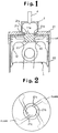
- Fig. 1 shows the cross-sectional profile of the combustion chamber of the thermally insulating engine related to the invention.
- Fig. 2 shows a top view of the main combustion chamber showing the combustion process.
- the piston 1 has the piston head 11 and the piston body 12 made of ceramics with high strength and heat resistance. They are mutually linked with the coupling ring 13.
- a truncated cone boss lla having a bottom with gentle outline is installed in the centre on the upper surface of the piston head 11.
- the upper surface of the piston head is formed in such a way that it slightly rises from the bottom to the peripheral portions and the main combustion chamber is formed between the upper inner wall of the cylinder and the upper surface of the piston head.
- the piston ring 14 is engaged in the upper portion of the piston body 12.
- the cylinder 2 has the cylinder head 21 and the cylinder liner 22 made of low thermal conductivity ceramics with resistance against high temperature.
- the subcombustion chamber 3 made of ceramics with high strength is installed on the upper portion of the hole 21a in the centre of the cylinder head 21.
- connection holes 21c are notched in the oblique radial direction at the specified angle.
- the connection holes 21c are arranged in an oblique pattern to the virtual face, which extends in the radial direction from the centre line of the cylinder 2.
- the nozzle 4, which injects fuel, is installed in the centre of the upper wall of the subcombustion chamber 3.
- the nozzle 4 is designed to inject the fuel to the subcombustion chamber 3 at the end of the compression process, and the fuel is ignited in the subcombustion chamber by air of high temperature, the temperature having risen during adiabatic compression.
- the internal pressure in the subcombustion chamber 3 rises within a short time and the fuel is injected from the said connection hole 21c into the main combustion chamber between the piston 1 and the cylinder 2.
- the reduction of the gap between the hole 21a of the cylinder head 21 and the bottom of the boss lla of the piston head 11 at the top-dead centre of the piston 1 is designed so that the gap area is between 3 and 10 percent in comparison with the area of the piston.
- the connection holes 21c connecting the subcombustion chamber 3 and the main combustion chamber need not always be holes as shown in the example, and may be grooves instead.
- the piston 1 goes up according to the rotation of the crankshaft and compresses air, then compresses air in the subcombustion chamber 3.
- the air current through the connection holes 21c generates a vortex in the subcombustion chamber when the peripheral edge of the boss lla approaches the lower edge of the hole 21a.
- This vortex expands from the lower portion towards the upper portion of the subcombustion chamber 3.
- the peripheral edge of the boss 11a reaches the upper edge of the hole 21a
- the space between the peripheral edge of the boss lla and the peripheral edge of the hole 21a is reduced. From this reduced space, air will be blown upwards through the hole 21a at high speed in the subcombustion chamber 3 because of the reduced area of the peripheral edge.
- the initial stage of combustion in the first example is performed with an abundance of fuel in the subcombustion chamber 3. Therefore, generation of NOx is controlled.
- the combustion condition of the middle to latter periods of combustion shows that unburned gas injected from the subcombustion chamber 3 into the main combustion chamber burns in an extensive area of the main combustion chamber and thus the fuel mixes well with air for combustion. Thus, generation of black smoke is controlled.
- the first example has the oblique connection holes to generate a vortex in the air, which passes between the main combustion chamber above the piston of the thermally insulating engine with a subcombustion chamber and the subcombustion chamber, or in the burning mixed air. Therefore, in the compression process, the air compressed by the piston generates a vortex in the subcombustion chamber and thus generation of mixed air is actively performed. As a result, mixed air, including flames from the subcombustion chamber, becomes a vortex in the combustion chamber above the piston during the initial stage of the combustion process. Thus, the vortex mixes well with air within the main combustion chamber for combustion. As a result, NOx and black smoke within exhaust gas will reduce.
- Fig. 3 shows the cross-sectional view of the second example of the thermally insulating engine according to the invention.
- Fig. 4 shows its longitudinal section.
- 102 is the cylinder
- 103 is the piston
- the combustor 101 in the second example is placed as the cylinder head on each cylinder.
- the combustor 101 has a flat cylindrical shape. Its structure will be explained in more detail below.
- Each of these combustors 101 is set into the cylinder head block (part of which is shown as 200 in Fig. 4), which is moulded by casting.
- the subcombustion chamber 111 is placed in the centre of the combustor 101.
- the air intake passage 112 and the exhaust passage 113 which are made into the shape of an arc, are provided.
- These passages as well as the side wall 114 of the subcombustion chamber 111 and the outer peripheral wall 115 have fine heat insulation.
- These parts use compound ceramics made of silicon nitride (Si 3 N 4 ), which has low thermal conductivity, and titanium oxide (TiO) or aluminum titanate (Al 2 TiO 5 ). To enhance moulding and casting performance, these parts are formed so that they have uniform wall thickness.
- the injection nozzle hole llla is drilled in the upper wall of the subcombustion chamber 111, and the hole 112a penetrating to the space 131, which is the combustion chamber on the top of the piston 103, is drilled in the lower wall.
- the outer wall 116 in the lower portion, which is coupled to the cylinder 102, uses ceramics made of silicon nitride (Si 3 N 4 ) with high strength.
- the boss 132 is installed on the top of the piston 103 and acts as the same as the boss lla in the first example.
- connection grooves 112b are cut to be oblique to the virtual face expanding in the radial direction from the centre line of the cylinder 102.
- the air intake 141 is equipped with the air intake valve 104 to guide fresh air by connecting the air intake passage 112 to the cylinder inside when the valve is open. To increase the area of the opening, two air intakes 141 are drilled, for example.
- the exhaust outlet 151 is equipped with the exhaust valve 105 to discharge exhaust gas after combustion via the exhaust passage 113 when the valve is open. Like the air intakes 141, two exhaust outlets are provided.
- the combustor 101 with the air intake/exhaust channels and the combustion chamber, as mentioned above, is moulded as a single unit by using ceramics only, without using metal.
- the subcombustion chamber 111 in which fuel is burned, and the exhaust passage 113 and the air intake passage 112, which are subject to high temperature, are separated by the side wall 114 and other parts made of ceramics of low thermal conductive material. Therefore, the high temperature caused by combustion heat will be blocked, even though these parts are adjacent to the subcombustion chamber by the single-unit structure. Thus, normal operation processes of the engine, including air intake, explosion and exhaust, will be performed without adverse influence. Also, the space required for the air intake passage 112 and the exhaust passage 113 can be reduced. In addition, a plurality of the air intakes 141 and the exhaust outlets 151 is installed, making air intake and exhaust to be efficiently performed. Thus, the piston 103 is powerfully driven to generate engine torque.
- the combustion chamber is positioned in the centre and the air intake and exhaust passages are arranged adjacent to the combustion chamber, the ceramics made of low thermal conductive material with heat resistance is used as side wall to form an assembly, and such an assembly is mounted on the top of the cylinder to form the thermally insulating engine.
- the ceramics made of low thermal conductive material with heat resistance is used as side wall to form an assembly, and such an assembly is mounted on the top of the cylinder to form the thermally insulating engine.
- Fig. 5 shows the top view of the third example of the invention.
- Fig. 6 shows the cross-sectional profile of part of the third example.
- Fig. 7 shows the channel drawing explaining the relationship between the air intake and exhaust channels as well as the valves of the third example.
- a box 201 is positioned above the engine having four cylinders. Inside the box, the subcombustion chambers 203a to 203d corresponding the four cylinders, the air intake channels 204a to 204d, the exhaust channels 205a to 205d, and the connection channels are integrated into an assembly. These parts use material flexible for casting. They are moulded by casting and stored in the box.
- the peripheral wall 231a which forms the subcombustion chamber 203a in its centre and which is made of ceramics using alumina (Al 2 O 3 ) or aluminum titanate (Al 2 TiO 5 ), the arc exhaust channel 205a to the left and the arc air intake channel 204a to the right are formed by the outer peripheral wall 202a and the air intake and exhaust partition 245a, which are made of ceramics of the same material.
- the combustion chamber and the air intake and exhaust channels are made into an assembly as the combustor 2A, below which the cylinder 12A with the piston 11A is installed as shown in Fig. 6.
- the engine having the air intake valve 13A and the exhaust valve 14A is formed.
- the boss 211 is installed on the top of the piston 11A and acts the same as the boss 11a in the first example.
- connection grooves 232 is provided around the peripheral edge of the hole 231 coupling the subcombustion chamber 203a and the main combustion chamber. Like the first example, the connection grooves 232 are cut to be slanted to the virtual face extending from the centre line of the cylinder 12A in the radial direction.
- the combustor 2B is adjacent to the right side of the combustor 2A in the Fig. 5, and is made into almost the same structure as with the combustor 2A.
- the air intake coupling channel 204ab couples the mutual air intake channels 204a and 204b.
- the exhaust channels 205a and 205b are coupled by the exhaust coupling channel 205ab.
- the set of combustors 2C and 2D is made into almost the same structure as with the set of combustors 2A and 2B in such a manner that the left and right are reversed.
- the exhaust coupling channel 205ab and the exhaust coupling channel 205cd of respective sets are connected with the coupling channel 205ad, and the opening/closing valve V5 is installed in the middle of the channel.
- the channels at both ends of the coupling channel 205ad are guided to the side face of the box 201 and openings are made in the specified positions as the exhaust sending outlets 205Ea and 205Ed.
- the air intake channel 204b of the combustor 2B and the air intake channel 204c of the combustor 2C are also coupled in such a manner that they are mutually connected. Because these air intake channels are connected to the supercharged air channel from the two turbochargers, they are branched into two channels and openings are made in the specified positions in the side face of the box 201 as the air intakes 204Ib and 204Ic.
- the turbochargers 206 and 207 have the turbines 261 and 271, the compressors 262 and 272, and the rotary electric machines 263 and 273. Respective turbines driven by exhaust energy rotate the compressors respectively coupled to the turbines and compress air to supply it to the engine as supercharged air. Respective rotary electric machines mounted to the turbine shaft are supplied with power from the battery, etc. when the engine rotates at a low speed and under a high load in accordance with the operation condition of the engine to operate as an electric motor.
- the rotary electric machines are designed to increase the engine torque by increasing the supercharged air, or operate as an electric generator when there is sufficient exhaust energy to collect exhaust energy as electric power and increase engine torque by supplying the said power, for example, to the electric motor combined to the crankshaft.
- the turbine housings 206a and 207a with the turbine scroll of the turbochargers 206 and 207 are moulded by using ceramics material with heat resistance and high strength. Their exhaust intakes 206b and 207b are formed so that they are directly connected to the said exhaust outlets 205Ea and 205Ed.
- the supercharged air supply outlets 206c and 207c of these turbochargers are directly connected to the said air intakes 204Ib and 204Ic.
- the supercharged air supply channel 206c in the lower portion of the turbocharger 206 is coupled to the fresh-air intake 207d via the connection tube 267.
- the opening/closing valve V1 is installed in the middle of the connection tube 267, and the opening/closing valve V2 is installed in the direction of outside air of the fresh-air intake 207d. Therefore, if the opening/closing valve V2 is closed and V1 is opened when both turbochargers 206 and 207 are driven, the supercharger system of the both turbochargers is connected in series to perform 2-stage supercharging so that high-pressure supercharged air is supplied to the engine.
- the opening/closing valve V3 is provided in the supercharged air supply channel of the turbocharger 206.
- the opening/closing valve V4 is provided in the exhaust insertion channel to the turbocharger 207. Opening/closing of the valves V3 and V4 as well as the said valves V1, V2 and V5 is designed to be controlled by instruction from the controller consisting of an electronic control device.
- the combustors 2A to 2D for the four cylinders are installed inside the box 201.
- the subcombustion chambers 203a to 203d, the air intake channels 204a to 204d, the exhaust channels 205a to 205d, and their coupling channels are cast so that they are mutually coupled as mentioned before with respective incoming/outgoing channels from/to the turbochargers 206 and 207. Therefore, the four-cylinder engine is assembled by installing the box 201 on the upper portion of the four cylinders.
- the combustors 2A to 2D are respectively equipped with the subcombustion chamber in the centre and the respective air intake channels and exhaust channels adjacent to the subcombustion chamber separated with the peripheral wall and the air intake/exhaust partition made of low thermal conductive material. Because of the good thermal insulation, normal air intake, explosion and exhaust processes are performed without any problem and adverse influence to operate the engine.
- both the turbochargers 206 and 207 are driven by exhaust energy from the set of combustors 2A and 2B and the set of combustors 2C and 2D, which consists of two cylinders respectively, to perform parallel operation.
- supercharged air is supplied to the four combustors to perform normal operation.
- the compressed air produced by the operations of the turbocharger 206 is guided to the turbocharger 207 via the channel equipped with the opening/closing valve V1 to be recompressed.
- strong supercharged air produced by the 2-stage turbochargers 206 and 207, which are serially connected, is supplied to the respective combustors 2A to 2D to perform operation.
- the combustion chamber for the four cylinders and its air intake and exhaust channels are separated with the wall made of material with low thermal conductivity to form the four compact combustors, which are placed adjacent, so that they are cast inside a single box. Therefore, the four-cylinder engine can be easily assembled by installing the box on the four cylinders.
- the supercharger system is designed to be flexibly switched between serial and parallel connection by installing the two turbochargers, which can be easily connected, and by controlling the opening/closing valves. Therefore, the supercharged air pressure can be properly controlled in accordance with the operation condition of the engine. As a result, a highly efficient engine can be obtained.
Landscapes
- Engineering & Computer Science (AREA)
- Chemical & Material Sciences (AREA)
- Combustion & Propulsion (AREA)
- Mechanical Engineering (AREA)
- General Engineering & Computer Science (AREA)
- Ceramic Engineering (AREA)
- Combustion Methods Of Internal-Combustion Engines (AREA)
Claims (11)
- Thermisch isolierter Motor, bei welchem die Flächen nahe dem Brennraum aus Isoliermaterial bestehen, wobei der Motor folgendes umfaßt:einen Zylinder (2, 102, 12A), in dem ein Kolben (1, 103, 11A) arbeitet;einen Vorsprung (11a, 132, 211) in der Mitte der oberen Oberfläche des Kolbens (1, 103, 11A);einen becherförmigen Zylinderkopf (21, 200, 201), der die Oberseite des Zylinders (2, 102, 12A) bedeckt;eine Öffnung (21a, 112a, 231), die auf der Mittelachse des Zylinderkopfs (21, 200, 201) angeordnet ist und in welche der Vorsprung (11a, 132, 211) an der oberen Oberfläche des Kolbens (1, 103, 11A) eingreift, wenn der Kolben (1, 103, 11A) den oberen Totpunkt erreicht;einen Nebenbrennraum (3, 111, 203a) aus Keramik, der über der Öffnung (21a, 112a, 231) angebracht ist und mit dem Hauptbrennraum, der durch den Zylinder gebildet wird, über die Öffnung (21a, 112a, 231) verbunden ist; undeine Brennstoffeinspritzdüse (4, 111a) zum Einspritzen von Brennstoff in den Nebenbrennraum (3, 111, 203a) ; gekennzeichnet durcheine Luftverbindungspassage (21c, 112b, 232) radial außerhalb der Öffnung (21a, 112a, 23 ), die entweder getrennt von der Öffnung oder als eine Nut in der Wand der Öffnung ausgebildet ist, zur Verbindung des Nebenbrennraums (3, 111, 203a) mit dem Hauptbrennraum, und dadurch, daßder Vorsprung (11a, 132, 211), der eine Kegelstumpfform aufweist, und der Zylinderkopf aus Keramik hergestellt ist.
- Thermisch isolierter Motor nach Anspruch 1, bei welchem die Luftverbindungspassage eine Mehrzahl von Öffnungen (21c) ist.
- Thermisch isolierter Motor nach Anspruch 1, bei welchem die Luftverbindungspassage eine Mehrzahl von Nuten (112b, 232) ist.
- Thermisch isolierter Motor nach einem der Ansprüche 1 bis 3, bei welchem die Luftverbindungspassage in einer schrägen Richtung zu der gedachten Fläche durchtritt, die sich von der Mittellinie des Zylinders in eine radiale Richtung erstreckt.
- Thermisch isolierter Motor nach einem der Ansprüche 1 bis 4, bei welchem die in dem Nebenbrennraum verwendete Keramik aus Siliciumnitrid ist.
- Thermisch isolierter Motor nach Anspruch 1, bei welchem:
der Nebenbrennraum (111) in der Mitte des Zylinderkopfs angeordnet und von Lufteinlaß- und -auslaßkanälen (112, 113) umgeben ist, wobei der Nebenbrennraum und die Lufteinlaß- und -auslaßkanäle durch Seitenwände (114) aus Keramik, die aus einem Material mit geringer Wärmeleitfähigkeit hergestellt sind, getrennt sind, so daß der Zylinderkopf als eine einzelne Baueinheit ausgebildet ist, welche den Nebenbrennraum und die Lufteinlaß- und -auslaßkanäle umfaßt. - Thermisch isolierter Motor nach Anspruch 6, bei welchem der Zylinderkopf in den Zylinderblock eingesetzt ist.
- Thermisch isolierter Motor nach Anspruch 6, bei welchem die Seitenwand des Nebenbrennraums und die äußere Umfangswand (115) des Zylinderkopfs mit gleichmäßiger Wanddicke ausgebildet sind.
- Thermisch isolierter Motor nach Anspruch 1, ferner umfassend:eine Mehrzahl von Zylindern, wobei sich in jedem ein Kolben hin- und herbewegt;einen Kasten (201), der über den Zylindern angebracht ist und eine Anordnung der Nebenbrennräume (203a-203d) enthält; wobei jeder Nebenbrennraum von einem umgebenden Lufteinlaß- und -auslaßkanal (204, 205) getrennt ist, wobei die Kanäle durch Trennwände (245a) getrennt sind, die aus einem Wärmeisoliermaterial hoher Festigkeit bestehen, so daß jeder Nebenbrennraum im Zentrum seiner Lufteinlaß- und -auslaßkanäle liegt;zwei Turbolader (206, 207), die mit den Lufteinlaß/auslaßkanälen verbunden sind und von welchen jeder Turbinenspiralen aufweist, die aus demselben Material wie die Trennwand hergestellt sind; undSchaltsteuermittel zum Umschalten des Ladesystems des Turboladers zwischen seriellem und parallelem Betrieb nach Maßgabe des Verbrennungszustands des Brennstoffes.
- Thermisch isolierter Motor nach Anspruch 9, bei welchem das Isoliermaterial aus Aluminiumoxid (Al2O3) oder Aluminiumtitanat (Al2TiO5) hergestellte Keramik ist.
- Thermisch isolierter Motor nach Anspruch 9 oder Anspruch 10, bei welchem die Schaltsteuermittel durch Anordnung von Öffnungs/Schließventilen in dem Ladekanal der beiden Turbolader und durch Umschalten des Ladesystems durch Auswahlsteuerung der Betätigung der Öffnungs/Schließventile gebildet werden.
Priority Applications (3)
| Application Number | Priority Date | Filing Date | Title |
|---|---|---|---|
| DE69316212T DE69316212T2 (de) | 1993-09-28 | 1993-09-28 | Maschine mit thermischer Isolation |
| EP93307662A EP0645529B1 (de) | 1993-09-28 | 1993-09-28 | Maschine mit thermischer Isolation |
| US08/127,372 US5447130A (en) | 1993-09-28 | 1993-09-28 | Thermally insulating engine |
Applications Claiming Priority (2)
| Application Number | Priority Date | Filing Date | Title |
|---|---|---|---|
| EP93307662A EP0645529B1 (de) | 1993-09-28 | 1993-09-28 | Maschine mit thermischer Isolation |
| US08/127,372 US5447130A (en) | 1993-09-28 | 1993-09-28 | Thermally insulating engine |
Publications (2)
| Publication Number | Publication Date |
|---|---|
| EP0645529A1 EP0645529A1 (de) | 1995-03-29 |
| EP0645529B1 true EP0645529B1 (de) | 1998-01-07 |
Family
ID=26134482
Family Applications (1)
| Application Number | Title | Priority Date | Filing Date |
|---|---|---|---|
| EP93307662A Expired - Lifetime EP0645529B1 (de) | 1993-09-28 | 1993-09-28 | Maschine mit thermischer Isolation |
Country Status (3)
| Country | Link |
|---|---|
| US (1) | US5447130A (de) |
| EP (1) | EP0645529B1 (de) |
| DE (1) | DE69316212T2 (de) |
Families Citing this family (11)
| Publication number | Priority date | Publication date | Assignee | Title |
|---|---|---|---|---|
| FR2776016B1 (fr) * | 1998-03-12 | 2000-06-30 | Lucas Conwell Frederic | Perfectionnement d'un moteur a combustion interne a injection |
| AU4744300A (en) * | 1999-05-25 | 2000-12-12 | Danfoss Compressors Gmbh | Axial piston refrigerant compressor |
| US6609490B2 (en) | 2001-11-15 | 2003-08-26 | John Flinchbaugh | Piston head for a spark ignition engine |
| US6510833B1 (en) * | 2001-12-20 | 2003-01-28 | American Diesel & Gas, Inc. | Fuel saving combustion engine insulation method and system |
| US7500464B2 (en) * | 2006-03-06 | 2009-03-10 | Lytesyde, Llc | Fuel processor apparatus and method for a diesel engine |
| US8205593B2 (en) * | 2009-06-17 | 2012-06-26 | De Versterre William I | DEV cycle engine |
| JP4975092B2 (ja) * | 2009-12-28 | 2012-07-11 | 川崎重工業株式会社 | 大型ガスエンジンの燃焼室 |
| US9086011B2 (en) * | 2010-01-22 | 2015-07-21 | Borgwarner Inc. | Directly communicated turbocharger |
| DE102010062415B4 (de) * | 2010-12-03 | 2020-03-12 | Continental Automotive Gmbh | Abgasturboladervorrichtung |
| DE102018005817B4 (de) * | 2018-07-20 | 2022-01-20 | Adrian Deckers | Verbrennungsmotor in Verbundbauweise mit annähernd parallel verlaufender Sekundärexpansion |
| CN114934838A (zh) * | 2022-05-26 | 2022-08-23 | 一汽解放汽车有限公司 | 一种预燃室结构、燃烧发动机及汽车 |
Family Cites Families (24)
| Publication number | Priority date | Publication date | Assignee | Title |
|---|---|---|---|---|
| USRE18429E (en) * | 1932-04-19 | Fuel injection engine | ||
| US2256776A (en) * | 1938-11-26 | 1941-09-23 | Kammer George Stephen | Compression ignition engine |
| US2511992A (en) * | 1945-04-11 | 1950-06-20 | Thomas E Quick | Internal-combustion engine |
| US2851020A (en) * | 1956-06-25 | 1958-09-09 | Gen Motors Corp | Cylinder construction for an internal combustion engine |
| US2983268A (en) * | 1959-05-07 | 1961-05-09 | Ralph M Heintz | Internal combustion engine |
| US3057334A (en) * | 1961-01-12 | 1962-10-09 | Caterpillar Tractor Co | Piston head with fuel directing means |
| FR1529533A (fr) * | 1965-11-23 | 1968-06-21 | Inst Francais Du Petrole | Perfectionnement aux moteurs à allumage par compression |
| DE3231112C2 (de) * | 1981-12-18 | 1984-12-06 | Boris Petrovič Bajkov | Brennkraftmaschine |
| JPS595862A (ja) * | 1982-06-30 | 1984-01-12 | Ngk Spark Plug Co Ltd | セラミツクシリンダ−ヘツド |
| US4791896A (en) * | 1982-07-29 | 1988-12-20 | Howard Bidwell | Water cooled scavenged crankcase type Otto internal combustion engine |
| US4594668A (en) * | 1983-02-16 | 1986-06-10 | Allied Corporation | Turbocharger control system |
| JPS61500862A (ja) * | 1983-12-27 | 1986-05-01 | フオ−ド モ−タ− カンパニ− | 内燃エンジン用のヘッド組立体 |
| US4561406A (en) * | 1984-05-25 | 1985-12-31 | Combustion Electromagnetics, Inc. | Winged reentrant electromagnetic combustion chamber |
| US4672933A (en) * | 1984-10-30 | 1987-06-16 | 501 NGK Spark Plug Co. Ltd. | Precombustion chamber with insulating means |
| JPS61145318A (ja) * | 1984-12-18 | 1986-07-03 | Kyocera Corp | セラミツクデイ−ゼルエンジン |
| US4781157A (en) * | 1987-12-24 | 1988-11-01 | Ford Motor Company | Multipart ceramic cylinder head |
| DE3903563C1 (de) * | 1988-07-19 | 1990-03-22 | Mtu Friedrichshafen Gmbh | |
| JP2718071B2 (ja) * | 1988-07-21 | 1998-02-25 | いすゞ自動車株式会社 | 副室式断熱エンジン |
| JPH086587B2 (ja) * | 1988-10-28 | 1996-01-24 | いすゞ自動車株式会社 | 副燃焼室式断熱エンジン |
| JP2711565B2 (ja) * | 1989-05-11 | 1998-02-10 | 株式会社いすゞセラミックス研究所 | エンジンのサイクル制御装置 |
| JPH0637852B2 (ja) * | 1989-07-17 | 1994-05-18 | いすゞ自動車株式会社 | 4サイクル断熱エンジン |
| JPH0668247B2 (ja) * | 1989-07-17 | 1994-08-31 | いすゞ自動車株式会社 | アルコール燃料を用いるセラミックエンジン |
| CA2056236C (en) * | 1991-11-26 | 2001-08-21 | Gary D. Webster | Internal combustion engine with high temperature variable geometry pre-combustion chamber |
| JPH05288123A (ja) * | 1992-04-10 | 1993-11-02 | Toyota Motor Corp | 内燃機関の排気ガス還流装置 |
-
1993
- 1993-09-28 EP EP93307662A patent/EP0645529B1/de not_active Expired - Lifetime
- 1993-09-28 US US08/127,372 patent/US5447130A/en not_active Expired - Fee Related
- 1993-09-28 DE DE69316212T patent/DE69316212T2/de not_active Expired - Fee Related
Also Published As
| Publication number | Publication date |
|---|---|
| US5447130A (en) | 1995-09-05 |
| DE69316212T2 (de) | 1998-07-16 |
| DE69316212D1 (de) | 1998-02-12 |
| EP0645529A1 (de) | 1995-03-29 |
Similar Documents
| Publication | Publication Date | Title |
|---|---|---|
| EP0645529B1 (de) | Maschine mit thermischer Isolation | |
| US5058537A (en) | Optimized high pressure internal combustion engines | |
| JP2002349272A (ja) | ピストン内燃機関 | |
| CA1054942A (en) | Compound spark-ignition and diesel engine | |
| KR101061862B1 (ko) | 2행정 왕복 내연기관의 작동 방법 | |
| JPS58152102A (ja) | 原動機 | |
| KR0145131B1 (ko) | 회전식 내연기관 및 압축기 | |
| WO2005121522A1 (ja) | 独立燃焼室式内燃機関 | |
| KR101045920B1 (ko) | 왕복 내연기관의 작동 방법 | |
| KR20010007159A (ko) | 대형 디젤 엔진용 과급기 군 | |
| JPH05156960A (ja) | 遮熱燃焼器とターボコンパウンド装置 | |
| US11441425B1 (en) | Separate compressor arrangements for engines | |
| WO1998003779A3 (en) | Engine having direct water injection during power stroke | |
| JP2993235B2 (ja) | 2サイクルエンジン | |
| KR19990022156A (ko) | 로우터리 내연기관 | |
| JP3074861B2 (ja) | 2サイクルエンジン | |
| CN210217907U (zh) | 一种滑片式内燃机 | |
| JPH0526051A (ja) | 断熱2−4サイクル切換エンジン | |
| PL145453B2 (en) | Turbine combustion engine in particular for powering vehicles | |
| TW202413792A (zh) | 二行程燃油引擎之改良 | |
| JPH10205332A (ja) | エンジンにおける燃焼室の構造 | |
| KR0171814B1 (ko) | 엔진의 에어공급장치 | |
| EP1497541B1 (de) | Drehkolben-verbrennungsmotor | |
| JP3096149B2 (ja) | 遮熱エンジンの燃焼室 | |
| JP2587276B2 (ja) | 断熱エンジン |
Legal Events
| Date | Code | Title | Description |
|---|---|---|---|
| PUAI | Public reference made under article 153(3) epc to a published international application that has entered the european phase |
Free format text: ORIGINAL CODE: 0009012 |
|
| AK | Designated contracting states |
Kind code of ref document: A1 Designated state(s): DE FR GB |
|
| 17P | Request for examination filed |
Effective date: 19950501 |
|
| 17Q | First examination report despatched |
Effective date: 19950717 |
|
| GRAG | Despatch of communication of intention to grant |
Free format text: ORIGINAL CODE: EPIDOS AGRA |
|
| GRAG | Despatch of communication of intention to grant |
Free format text: ORIGINAL CODE: EPIDOS AGRA |
|
| GRAH | Despatch of communication of intention to grant a patent |
Free format text: ORIGINAL CODE: EPIDOS IGRA |
|
| GRAH | Despatch of communication of intention to grant a patent |
Free format text: ORIGINAL CODE: EPIDOS IGRA |
|
| GRAA | (expected) grant |
Free format text: ORIGINAL CODE: 0009210 |
|
| AK | Designated contracting states |
Kind code of ref document: B1 Designated state(s): DE FR GB |
|
| REF | Corresponds to: |
Ref document number: 69316212 Country of ref document: DE Date of ref document: 19980212 |
|
| ET | Fr: translation filed | ||
| PLBE | No opposition filed within time limit |
Free format text: ORIGINAL CODE: 0009261 |
|
| STAA | Information on the status of an ep patent application or granted ep patent |
Free format text: STATUS: NO OPPOSITION FILED WITHIN TIME LIMIT |
|
| 26N | No opposition filed | ||
| PGFP | Annual fee paid to national office [announced via postgrant information from national office to epo] |
Ref country code: FR Payment date: 20000912 Year of fee payment: 8 |
|
| PGFP | Annual fee paid to national office [announced via postgrant information from national office to epo] |
Ref country code: DE Payment date: 20000918 Year of fee payment: 8 |
|
| PGFP | Annual fee paid to national office [announced via postgrant information from national office to epo] |
Ref country code: GB Payment date: 20000927 Year of fee payment: 8 |
|
| PG25 | Lapsed in a contracting state [announced via postgrant information from national office to epo] |
Ref country code: GB Free format text: LAPSE BECAUSE OF NON-PAYMENT OF DUE FEES Effective date: 20010928 |
|
| REG | Reference to a national code |
Ref country code: GB Ref legal event code: IF02 |
|
| PG25 | Lapsed in a contracting state [announced via postgrant information from national office to epo] |
Ref country code: DE Free format text: LAPSE BECAUSE OF NON-PAYMENT OF DUE FEES Effective date: 20020501 |
|
| GBPC | Gb: european patent ceased through non-payment of renewal fee |
Effective date: 20010928 |
|
| PG25 | Lapsed in a contracting state [announced via postgrant information from national office to epo] |
Ref country code: FR Free format text: LAPSE BECAUSE OF NON-PAYMENT OF DUE FEES Effective date: 20020531 |
|
| REG | Reference to a national code |
Ref country code: FR Ref legal event code: ST |