EP0645523B1 - Brennkraftmaschine - Google Patents
Brennkraftmaschine Download PDFInfo
- Publication number
- EP0645523B1 EP0645523B1 EP94108429A EP94108429A EP0645523B1 EP 0645523 B1 EP0645523 B1 EP 0645523B1 EP 94108429 A EP94108429 A EP 94108429A EP 94108429 A EP94108429 A EP 94108429A EP 0645523 B1 EP0645523 B1 EP 0645523B1
- Authority
- EP
- European Patent Office
- Prior art keywords
- valve
- intake valve
- combustion engine
- internal
- centre
- Prior art date
- Legal status (The legal status is an assumption and is not a legal conclusion. Google has not performed a legal analysis and makes no representation as to the accuracy of the status listed.)
- Expired - Lifetime
Links
Images


Classifications
-
- F—MECHANICAL ENGINEERING; LIGHTING; HEATING; WEAPONS; BLASTING
- F02—COMBUSTION ENGINES; HOT-GAS OR COMBUSTION-PRODUCT ENGINE PLANTS
- F02M—SUPPLYING COMBUSTION ENGINES IN GENERAL WITH COMBUSTIBLE MIXTURES OR CONSTITUENTS THEREOF
- F02M35/00—Combustion-air cleaners, air intakes, intake silencers, or induction systems specially adapted for, or arranged on, internal-combustion engines
- F02M35/10—Air intakes; Induction systems
- F02M35/10242—Devices or means connected to or integrated into air intakes; Air intakes combined with other engine or vehicle parts
- F02M35/10288—Air intakes combined with another engine part, e.g. cylinder head cover or being cast in one piece with the exhaust manifold, cylinder head or engine block
-
- F—MECHANICAL ENGINEERING; LIGHTING; HEATING; WEAPONS; BLASTING
- F01—MACHINES OR ENGINES IN GENERAL; ENGINE PLANTS IN GENERAL; STEAM ENGINES
- F01L—CYCLICALLY OPERATING VALVES FOR MACHINES OR ENGINES
- F01L1/00—Valve-gear or valve arrangements, e.g. lift-valve gear
- F01L1/26—Valve-gear or valve arrangements, e.g. lift-valve gear characterised by the provision of two or more valves operated simultaneously by same transmitting-gear; peculiar to machines or engines with more than two lift-valves per cylinder
- F01L1/265—Valve-gear or valve arrangements, e.g. lift-valve gear characterised by the provision of two or more valves operated simultaneously by same transmitting-gear; peculiar to machines or engines with more than two lift-valves per cylinder peculiar to machines or engines with three or more intake valves per cylinder
-
- F—MECHANICAL ENGINEERING; LIGHTING; HEATING; WEAPONS; BLASTING
- F01—MACHINES OR ENGINES IN GENERAL; ENGINE PLANTS IN GENERAL; STEAM ENGINES
- F01L—CYCLICALLY OPERATING VALVES FOR MACHINES OR ENGINES
- F01L13/00—Modifications of valve-gear to facilitate reversing, braking, starting, changing compression ratio, or other specific operations
- F01L13/0005—Deactivating valves
-
- F—MECHANICAL ENGINEERING; LIGHTING; HEATING; WEAPONS; BLASTING
- F02—COMBUSTION ENGINES; HOT-GAS OR COMBUSTION-PRODUCT ENGINE PLANTS
- F02B—INTERNAL-COMBUSTION PISTON ENGINES; COMBUSTION ENGINES IN GENERAL
- F02B27/00—Use of kinetic or wave energy of charge in induction systems, or of combustion residues in exhaust systems, for improving quantity of charge or for increasing removal of combustion residues
- F02B27/02—Use of kinetic or wave energy of charge in induction systems, or of combustion residues in exhaust systems, for improving quantity of charge or for increasing removal of combustion residues the systems having variable, i.e. adjustable, cross-sectional areas, chambers of variable volume, or like variable means
-
- F—MECHANICAL ENGINEERING; LIGHTING; HEATING; WEAPONS; BLASTING
- F02—COMBUSTION ENGINES; HOT-GAS OR COMBUSTION-PRODUCT ENGINE PLANTS
- F02B—INTERNAL-COMBUSTION PISTON ENGINES; COMBUSTION ENGINES IN GENERAL
- F02B27/00—Use of kinetic or wave energy of charge in induction systems, or of combustion residues in exhaust systems, for improving quantity of charge or for increasing removal of combustion residues
- F02B27/02—Use of kinetic or wave energy of charge in induction systems, or of combustion residues in exhaust systems, for improving quantity of charge or for increasing removal of combustion residues the systems having variable, i.e. adjustable, cross-sectional areas, chambers of variable volume, or like variable means
- F02B27/0205—Use of kinetic or wave energy of charge in induction systems, or of combustion residues in exhaust systems, for improving quantity of charge or for increasing removal of combustion residues the systems having variable, i.e. adjustable, cross-sectional areas, chambers of variable volume, or like variable means characterised by the charging effect
- F02B27/0215—Oscillating pipe charging, i.e. variable intake pipe length charging
- F02B27/0221—Resonance charging combined with oscillating pipe charging
-
- F—MECHANICAL ENGINEERING; LIGHTING; HEATING; WEAPONS; BLASTING
- F02—COMBUSTION ENGINES; HOT-GAS OR COMBUSTION-PRODUCT ENGINE PLANTS
- F02B—INTERNAL-COMBUSTION PISTON ENGINES; COMBUSTION ENGINES IN GENERAL
- F02B27/00—Use of kinetic or wave energy of charge in induction systems, or of combustion residues in exhaust systems, for improving quantity of charge or for increasing removal of combustion residues
- F02B27/02—Use of kinetic or wave energy of charge in induction systems, or of combustion residues in exhaust systems, for improving quantity of charge or for increasing removal of combustion residues the systems having variable, i.e. adjustable, cross-sectional areas, chambers of variable volume, or like variable means
- F02B27/0226—Use of kinetic or wave energy of charge in induction systems, or of combustion residues in exhaust systems, for improving quantity of charge or for increasing removal of combustion residues the systems having variable, i.e. adjustable, cross-sectional areas, chambers of variable volume, or like variable means characterised by the means generating the charging effect
- F02B27/0247—Plenum chambers; Resonance chambers or resonance pipes
- F02B27/0252—Multiple plenum chambers or plenum chambers having inner separation walls, e.g. comprising valves for the same group of cylinders
-
- F—MECHANICAL ENGINEERING; LIGHTING; HEATING; WEAPONS; BLASTING
- F02—COMBUSTION ENGINES; HOT-GAS OR COMBUSTION-PRODUCT ENGINE PLANTS
- F02B—INTERNAL-COMBUSTION PISTON ENGINES; COMBUSTION ENGINES IN GENERAL
- F02B27/00—Use of kinetic or wave energy of charge in induction systems, or of combustion residues in exhaust systems, for improving quantity of charge or for increasing removal of combustion residues
- F02B27/02—Use of kinetic or wave energy of charge in induction systems, or of combustion residues in exhaust systems, for improving quantity of charge or for increasing removal of combustion residues the systems having variable, i.e. adjustable, cross-sectional areas, chambers of variable volume, or like variable means
- F02B27/0226—Use of kinetic or wave energy of charge in induction systems, or of combustion residues in exhaust systems, for improving quantity of charge or for increasing removal of combustion residues the systems having variable, i.e. adjustable, cross-sectional areas, chambers of variable volume, or like variable means characterised by the means generating the charging effect
- F02B27/0289—Intake runners having multiple intake valves per cylinder
-
- F—MECHANICAL ENGINEERING; LIGHTING; HEATING; WEAPONS; BLASTING
- F02—COMBUSTION ENGINES; HOT-GAS OR COMBUSTION-PRODUCT ENGINE PLANTS
- F02B—INTERNAL-COMBUSTION PISTON ENGINES; COMBUSTION ENGINES IN GENERAL
- F02B75/00—Other engines
- F02B75/16—Engines characterised by number of cylinders, e.g. single-cylinder engines
- F02B75/18—Multi-cylinder engines
- F02B75/24—Multi-cylinder engines with cylinders arranged oppositely relative to main shaft and of "flat" type
- F02B75/243—Multi-cylinder engines with cylinders arranged oppositely relative to main shaft and of "flat" type with only one crankshaft of the "boxer" type, e.g. all connecting rods attached to separate crankshaft bearings
-
- F—MECHANICAL ENGINEERING; LIGHTING; HEATING; WEAPONS; BLASTING
- F02—COMBUSTION ENGINES; HOT-GAS OR COMBUSTION-PRODUCT ENGINE PLANTS
- F02F—CYLINDERS, PISTONS OR CASINGS, FOR COMBUSTION ENGINES; ARRANGEMENTS OF SEALINGS IN COMBUSTION ENGINES
- F02F1/00—Cylinders; Cylinder heads
- F02F1/24—Cylinder heads
- F02F1/42—Shape or arrangement of intake or exhaust channels in cylinder heads
- F02F1/4214—Shape or arrangement of intake or exhaust channels in cylinder heads specially adapted for four or more valves per cylinder
-
- F—MECHANICAL ENGINEERING; LIGHTING; HEATING; WEAPONS; BLASTING
- F02—COMBUSTION ENGINES; HOT-GAS OR COMBUSTION-PRODUCT ENGINE PLANTS
- F02M—SUPPLYING COMBUSTION ENGINES IN GENERAL WITH COMBUSTIBLE MIXTURES OR CONSTITUENTS THEREOF
- F02M35/00—Combustion-air cleaners, air intakes, intake silencers, or induction systems specially adapted for, or arranged on, internal-combustion engines
- F02M35/10—Air intakes; Induction systems
- F02M35/10006—Air intakes; Induction systems characterised by the position of elements of the air intake system in direction of the air intake flow, i.e. between ambient air inlet and supply to the combustion chamber
- F02M35/10026—Plenum chambers
- F02M35/10045—Multiple plenum chambers; Plenum chambers having inner separation walls
-
- F—MECHANICAL ENGINEERING; LIGHTING; HEATING; WEAPONS; BLASTING
- F02—COMBUSTION ENGINES; HOT-GAS OR COMBUSTION-PRODUCT ENGINE PLANTS
- F02M—SUPPLYING COMBUSTION ENGINES IN GENERAL WITH COMBUSTIBLE MIXTURES OR CONSTITUENTS THEREOF
- F02M35/00—Combustion-air cleaners, air intakes, intake silencers, or induction systems specially adapted for, or arranged on, internal-combustion engines
- F02M35/10—Air intakes; Induction systems
- F02M35/10006—Air intakes; Induction systems characterised by the position of elements of the air intake system in direction of the air intake flow, i.e. between ambient air inlet and supply to the combustion chamber
- F02M35/10072—Intake runners
-
- F—MECHANICAL ENGINEERING; LIGHTING; HEATING; WEAPONS; BLASTING
- F02—COMBUSTION ENGINES; HOT-GAS OR COMBUSTION-PRODUCT ENGINE PLANTS
- F02M—SUPPLYING COMBUSTION ENGINES IN GENERAL WITH COMBUSTIBLE MIXTURES OR CONSTITUENTS THEREOF
- F02M35/00—Combustion-air cleaners, air intakes, intake silencers, or induction systems specially adapted for, or arranged on, internal-combustion engines
- F02M35/10—Air intakes; Induction systems
- F02M35/104—Intake manifolds
- F02M35/1047—Intake manifolds characterised by some cylinders being fed from one side of engine block and the other cylinders being fed from the other side of engine block
-
- F—MECHANICAL ENGINEERING; LIGHTING; HEATING; WEAPONS; BLASTING
- F02—COMBUSTION ENGINES; HOT-GAS OR COMBUSTION-PRODUCT ENGINE PLANTS
- F02M—SUPPLYING COMBUSTION ENGINES IN GENERAL WITH COMBUSTIBLE MIXTURES OR CONSTITUENTS THEREOF
- F02M35/00—Combustion-air cleaners, air intakes, intake silencers, or induction systems specially adapted for, or arranged on, internal-combustion engines
- F02M35/10—Air intakes; Induction systems
- F02M35/104—Intake manifolds
- F02M35/108—Intake manifolds with primary and secondary intake passages
- F02M35/1085—Intake manifolds with primary and secondary intake passages the combustion chamber having multiple intake valves
-
- F—MECHANICAL ENGINEERING; LIGHTING; HEATING; WEAPONS; BLASTING
- F02—COMBUSTION ENGINES; HOT-GAS OR COMBUSTION-PRODUCT ENGINE PLANTS
- F02M—SUPPLYING COMBUSTION ENGINES IN GENERAL WITH COMBUSTIBLE MIXTURES OR CONSTITUENTS THEREOF
- F02M35/00—Combustion-air cleaners, air intakes, intake silencers, or induction systems specially adapted for, or arranged on, internal-combustion engines
- F02M35/10—Air intakes; Induction systems
- F02M35/104—Intake manifolds
- F02M35/116—Intake manifolds for engines with cylinders in V-arrangement or arranged oppositely relative to the main shaft
-
- F—MECHANICAL ENGINEERING; LIGHTING; HEATING; WEAPONS; BLASTING
- F02—COMBUSTION ENGINES; HOT-GAS OR COMBUSTION-PRODUCT ENGINE PLANTS
- F02M—SUPPLYING COMBUSTION ENGINES IN GENERAL WITH COMBUSTIBLE MIXTURES OR CONSTITUENTS THEREOF
- F02M35/00—Combustion-air cleaners, air intakes, intake silencers, or induction systems specially adapted for, or arranged on, internal-combustion engines
- F02M35/10—Air intakes; Induction systems
- F02M35/104—Intake manifolds
- F02M35/116—Intake manifolds for engines with cylinders in V-arrangement or arranged oppositely relative to the main shaft
- F02M35/1165—Boxer or pancake engines
-
- F—MECHANICAL ENGINEERING; LIGHTING; HEATING; WEAPONS; BLASTING
- F02—COMBUSTION ENGINES; HOT-GAS OR COMBUSTION-PRODUCT ENGINE PLANTS
- F02B—INTERNAL-COMBUSTION PISTON ENGINES; COMBUSTION ENGINES IN GENERAL
- F02B1/00—Engines characterised by fuel-air mixture compression
- F02B1/02—Engines characterised by fuel-air mixture compression with positive ignition
- F02B1/04—Engines characterised by fuel-air mixture compression with positive ignition with fuel-air mixture admission into cylinder
-
- F—MECHANICAL ENGINEERING; LIGHTING; HEATING; WEAPONS; BLASTING
- F02—COMBUSTION ENGINES; HOT-GAS OR COMBUSTION-PRODUCT ENGINE PLANTS
- F02B—INTERNAL-COMBUSTION PISTON ENGINES; COMBUSTION ENGINES IN GENERAL
- F02B75/00—Other engines
- F02B75/02—Engines characterised by their cycles, e.g. six-stroke
- F02B2075/022—Engines characterised by their cycles, e.g. six-stroke having less than six strokes per cycle
- F02B2075/027—Engines characterised by their cycles, e.g. six-stroke having less than six strokes per cycle four
-
- F—MECHANICAL ENGINEERING; LIGHTING; HEATING; WEAPONS; BLASTING
- F02—COMBUSTION ENGINES; HOT-GAS OR COMBUSTION-PRODUCT ENGINE PLANTS
- F02B—INTERNAL-COMBUSTION PISTON ENGINES; COMBUSTION ENGINES IN GENERAL
- F02B75/00—Other engines
- F02B75/16—Engines characterised by number of cylinders, e.g. single-cylinder engines
- F02B75/18—Multi-cylinder engines
- F02B2075/1804—Number of cylinders
- F02B2075/1824—Number of cylinders six
-
- F—MECHANICAL ENGINEERING; LIGHTING; HEATING; WEAPONS; BLASTING
- F02—COMBUSTION ENGINES; HOT-GAS OR COMBUSTION-PRODUCT ENGINE PLANTS
- F02B—INTERNAL-COMBUSTION PISTON ENGINES; COMBUSTION ENGINES IN GENERAL
- F02B2275/00—Other engines, components or details, not provided for in other groups of this subclass
- F02B2275/18—DOHC [Double overhead camshaft]
-
- F—MECHANICAL ENGINEERING; LIGHTING; HEATING; WEAPONS; BLASTING
- F02—COMBUSTION ENGINES; HOT-GAS OR COMBUSTION-PRODUCT ENGINE PLANTS
- F02F—CYLINDERS, PISTONS OR CASINGS, FOR COMBUSTION ENGINES; ARRANGEMENTS OF SEALINGS IN COMBUSTION ENGINES
- F02F7/00—Casings, e.g. crankcases
- F02F7/006—Camshaft or pushrod housings
-
- F—MECHANICAL ENGINEERING; LIGHTING; HEATING; WEAPONS; BLASTING
- F02—COMBUSTION ENGINES; HOT-GAS OR COMBUSTION-PRODUCT ENGINE PLANTS
- F02M—SUPPLYING COMBUSTION ENGINES IN GENERAL WITH COMBUSTIBLE MIXTURES OR CONSTITUENTS THEREOF
- F02M35/00—Combustion-air cleaners, air intakes, intake silencers, or induction systems specially adapted for, or arranged on, internal-combustion engines
- F02M35/10—Air intakes; Induction systems
- F02M35/10006—Air intakes; Induction systems characterised by the position of elements of the air intake system in direction of the air intake flow, i.e. between ambient air inlet and supply to the combustion chamber
- F02M35/10078—Connections of intake systems to the engine
- F02M35/10085—Connections of intake systems to the engine having a connecting piece, e.g. a flange, between the engine and the air intake being foreseen with a throttle valve, fuel injector, mixture ducts or the like
-
- Y—GENERAL TAGGING OF NEW TECHNOLOGICAL DEVELOPMENTS; GENERAL TAGGING OF CROSS-SECTIONAL TECHNOLOGIES SPANNING OVER SEVERAL SECTIONS OF THE IPC; TECHNICAL SUBJECTS COVERED BY FORMER USPC CROSS-REFERENCE ART COLLECTIONS [XRACs] AND DIGESTS
- Y02—TECHNOLOGIES OR APPLICATIONS FOR MITIGATION OR ADAPTATION AGAINST CLIMATE CHANGE
- Y02T—CLIMATE CHANGE MITIGATION TECHNOLOGIES RELATED TO TRANSPORTATION
- Y02T10/00—Road transport of goods or passengers
- Y02T10/10—Internal combustion engine [ICE] based vehicles
- Y02T10/12—Improving ICE efficiencies
Definitions
- the invention relates to an internal combustion engine according to the preamble of Claim 1.
- a four-stroke internal combustion engine is known from EP 0 063 385 B1 each combustion chamber work three intake valves and two exhaust valves with which the Charge itself and the charge changes when operating the internal combustion engine should be improved.
- an internal combustion engine is also with four valves per cylinder known, three of which as intake valves and one as Exhaust valve are formed.
- the valves are arranged so that a first and a second intake valve on one side of the median longitudinal plane of the cylinder bank and that third inlet valve together with the outlet valve on the other side of the Central longitudinal plane are arranged.
- first and third intake valve each designed as a throttle valve Inlet control valve is arranged with which the air supply in the combustion chamber can be controlled.
- the object of the invention is to provide a multi-valve arrangement for an advanced Four stroke internal combustion engine to create using three intake valves and an exhaust valve the operation of this internal combustion engine with good performance and high torque with regard to consumption and elimination of exhaust emissions improved. But it should also be ensured that the construction effort is within a reasonable range.
- the first and the second inlet valve are according to the invention by means of switching elements controllable, e.g. switched between the camshaft and these intake valves can be hydraulic ram, as described in PCT / EP92 / 00502.
- switching elements controllable e.g. switched between the camshaft and these intake valves can be hydraulic ram, as described in PCT / EP92 / 00502.
- power, torque, consumption and exhaust emissions are the Internal combustion engine can be influenced favorably.
- the third permanently actuated intake valve is arranged on the side of the exhaust valve, resulting in a desired rapid heating of the associated with this part-load valve Suction line leads.
- said valve arrangement is a combination based on cross-flow and uni-flow principle in the cylinder head.
- Another advantage of this training is that the three intake valves and The design of the exhaust valve is an optimum between three-valve technology (two intake valves; one exhaust valve) and five-valve technology (three intake valves, two Represent exhaust valves).
- This multi-valve configuration only requires two existing camshafts.
- This training can be advantageously combined with separate Suction lines for the first and the second inlet valve and the third, respectively Intake valve take place, the suction line of the third inlet valve at least can be integrated in sections into the cylinder head cover.
- valves are arranged in the combustion chamber in such a way that spatially advantageous conditions arise, also in connection with separate Suction lines.
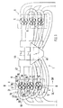
- An internal combustion engine 1 of the reciprocating type with multiple ignition comprises a plurality of cylinders 2, 3, 4 and 5, 6, 7 and opposing rows of cylinders 8, 9.
- the cylinders 2, 3, 4 are accommodated in a cylinder crankcase 10 which has a cylinder head 11 with combustion chambers 12, 13, 14 includes.
- Gas exchange valves operate in each combustion chamber 12, which are represented by three inlet valves, namely a first inlet valve 15, a second inlet valve 16 and a third inlet valve 17 and an outlet valve 18.
- the valves, for example second inlet valve 16 and third inlet valve 17, are globe valves with valve stem 19 and valve disk 20 (FIG. 3).
- valves work together with the aid of hydraulic tappets 21, 22 with camshafts 23, 23 'which are arranged in the cylinder head 11 or between the latter and a cylinder hood 24 covering the cylinder head.
- the valve plates 20 of the valves 15, 16, 17, 18 act on valve openings 25, 26, 27, 28, which limit the suction channels 29, 30, 31 and an outlet channel 32 with respect to the combustion chamber 12.
- the valve openings 25, 26, 27, 28 surround valve opening centers 33, 34, 35, 36 (FIG. 2). With Ev1 and Ev2, injection valves for the intake valves 16 and 17 are designated.
- valve opening centers 33, 34 of the first intake valve 15 and the second Inlet valve 16 are on one side SR of a central longitudinal plane B-B Internal combustion engine 1, for example, a center line of a not shown Can include crankshaft.
- valve opening centers 35, 36 of the third inlet valve 17 and the outlet valve 18 on the other side SL of this Central longitudinal plane B-B arranged.
- the diameter D 17 of the valve opening 27 of the third valve 17 is smaller than that Diameter D 15 and D 16 of the other intake valves 16 and 17, however, is the Diameter D 16 of the valve opening 26 of the second inlet valve 16 is smaller than that Diameter D 15 of the valve opening 25 of the first inlet valve 15.
- the valve opening 28 of the exhaust valve 18 is larger than the valve openings of the intake valves, the The size of all valves is determined mathematically / iteratively or empirically.
- the third inlet valve 17 as well as the outlet valve 18 is during the Operation of the internal combustion engine 1 permanently actuated by the camshaft 23 '.
- the first inlet valve 15 and the second inlet valve 16 from Switching elements 37 during operation of the internal combustion engine switched off. Switching elements of this type are dealt with by the PCT / EP92 / 00502.
- the connection is, for example, dependent on load and speed.
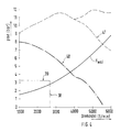
- Fig. 4 shows a diagram in which on the abscissa the speed (1 / min) and on which the ordinate of the mean pressure pme is plotted.
- One vertical and one horizontal lines 38, 39 delimit an area of the field that has a favorable consumption and represents a cheaper mass emission.
- At 40 is a first full load line referred to, below which only the third inlet valve 17 operates. Beyond This First Full load line 40, the second inlet valve 16 is switched on - switching element 37 - so that then the third inlet valve 17 and the second inlet valve 16 together work.
- a further full load line 41 is also entered in the diagram, ab which all inlet valves 15, 16, 17 are effective.
- a driving resistance line a motor vehicle is designated Fwsl.
- the first inlet valve 15 and the second inlet valve 16 are over a first direct suction line 42 and the third inlet valve 17 via a second Suction line 43 medium, a fuel-air mixture, supplied.
- the second suction line 43 can be designed as a deflection line with a 90 ° bend 44. However, it does exist also the possibility of closing the second suction line 43 into the cylinder head cover 24 integrate (Fig. 3), both versions crossing the cylinder head 11.
- At 43 ' is a separate connecting pipe section between the suction line 43 and the cylinder head 11 indicated.
- the first suction line 42 is part of a first suction system 44, the second Suction line 43 of a second suction system 45. Both suction lines 44 and 45 are separated from each other.
- the first suction line 42 is relatively short and relatively large cross-section - for full load range -; whereas the second suction line 43 is relatively long and with a relatively small cross section - for part-load range -.
- spark plug bore 47 is indicated, the Spark plug center ZKz is located near the combustion chamber center Bz.
Landscapes
- Engineering & Computer Science (AREA)
- Mechanical Engineering (AREA)
- General Engineering & Computer Science (AREA)
- Chemical & Material Sciences (AREA)
- Combustion & Propulsion (AREA)
- Valve-Gear Or Valve Arrangements (AREA)
- Valve Device For Special Equipments (AREA)
- Cylinder Crankcases Of Internal Combustion Engines (AREA)
Description
- Fig. 1
- eine schematische Ansicht von oben auf eine mehrzylindrige Brennkraftmaschine mit der erfindungsgemäßen multiplen Ventilanordnung,
- Fig. 2
- eine Einzelheit X der Fig. 1 in größerem Maßstab,
- Fig. 3
- einen Schnitt nach der Linie III-III der Fig. 2,
- Fig. 4
- ein Diagramm, aus dem Betriebszustände der Brennkraftmaschine hervorgehen.
Mit Ev1 und Ev2 sind Einspritzventile für die Einlaßventile 16 und 17 bezeichnet.
- Der Winkel w3 für das Ventilöffnungszentrum 33 der Ventilöffnung 25 des ersten Einlaßventils 15 beträgt zwischen 15° und 25°
- der Winkel w4 für das Ventilöffnungszentrum 34 der Ventilöffnung 26 des zweiten Einlaßventils 16 beträgt zwischen 50° und 60°
- der Winkel w5 für das Ventilöffnungszentrum 35 der Ventilöffnung 27 des dritten Einlaßventils 17 beträgt zwischen 50° und 60°
- der Winkel w6 für das Ventilöffnungszentrum 36 der Ventilöffnung 28 des Auslaßventils 18 beträgt zwischen 40°und 50°.
Claims (10)
- Brennkraftmaschine der Viertaktbauart mit mindestens einer Zylinderreihe mit drei Einlaßventilen und einem Auslaßventil pro Zylinder, wobei diese Ventile von in einem Zylinderkopf angeordneten Nockenwellen betätigt werden und mit Ventiltellern auf unterschiedliche Durchmesser aufweisende Ventilöffnungen eines Brennraums einwirken, deren Ventilöffnungszentren beiderseits einer Mittellängsebene liegen, wobei die Ventile (15, 16, 17, 18) in der Weise angeordnet sind, daß die Ventilöffnungszentren (33, 34) der Ventilöffnungen (25, 26) des ersten Einlaßventils (15) und des zweiten Einlaßventils (16) auf der einen Seite SR der Mittellängsebene B-B liegen, wogegen die Ventilöffnungszentren (35, 36) der Ventilöffnungen (27, 28) des dritten Einlaßventils (17) und des Auslaßventils (18) auf der anderen Seite SL der Mittellängsebene B-B liegen, dadurch gekennzeichnet, daß das dritte Einlaßventil (17) während des Betriebs der Brennkraftmaschine (1) permanent betätigt wird und daß das erste Einlaßventil (15) und das zweite Einlaßventil (16) mittels Schaltelementen (37) und in Abhängigkeit von Brennkraftmaschinenparametern wie Last, Drehzahl oder dgl. zuschaltbar ist.
- Brennkraftmaschine nach Anspruch 1, bei der die Ventile im Querschnitt des Zylinderkopfs gesehen im Winkel zu der Mittellängsebene angeordnet sind, dadurch gekennzeichnet, daß das zweite Ventil (16) und das dritte Ventil (17) in etwa mit gleichem Winkel (w1; w2) zur Mittellängsebene B-B angeordnet sind.
- Brennkraftmaschine nach Anspruch 1, dadurch gekennzeichnet, daß der Durchmesser (D 16) der Ventilöffnung (27) des dritten Ventils (16) kleiner ist als der Durchmesser (D 15 und D 16) der übrigen Einlaßventile (15, 16).
- Brennkraftmaschine nach Anspruch 1, dadurch gekennzeichnet, daß der Durchmesser (D 5) der Ventilöffnung (26) des zweiten Einlaßventils (16) größer ist als der Durchmesser (D 16) der Ventilöffnung (27) des dritten Einlaßventils (17), jedoch ist dieser Durchmesser (D 16) kleiner als der Durchmesser (D 14) der Ventilöffnung (25) des ersten Einlaßventils (15).
- Brennkraftmaschine nach einem der Ansprüche 1 bis 4, dadurch gekennzeichnet, daß dem ersten Einlaßventil (15) und dem zweiten Einlaßventil (16) über eine erste direkte Saugleitung (42) und dem dritten Einlaßventil (17) über eine zweite, den Zylinderkopf (11) überquerende Saugleitung (43) Medium zugeführt wird.
- Brennkraftmaschine nach Anspruch 5, dadurch gekennzeichnet, daß die zweite Saugleitung (43) in eine Zylinderkopfhaube (24) integriert ist.
- Brennkraftmaschine nach den Ansprüchen 5 und 6, dadurch gekennzeichnet, daß die erste Saugleitung (42) und die zweite Saugleitung (43) jeweils Bestandteil von getrennten Sauganlagen (44, 45) sind.
- Brennkraftmaschine nach einem oder mehreren der vorangehenden Ansprüche, bei der der jeweilige Brennraum - von oben gesehen - von einer Umfangslinie begrenzt wird und ein Brennraumzentrum umfaßt, das eine Querebene des Zylinderkopfs einschließt und die Ventilöffnungszentren der Ventilöffnungen auf, das Brennraumzentrum schneidenden, radialen Konstruktionslinien liegen, die zur Querbene im Winkel angeordnet sind, dadurch gekennzeichnet, daßder Winkel w3 für das Ventilöffnungszentrum (33) der Ventilöffnung (25) des ersten Einlaßventils (15) zwischen 15° und 25° beträgt;der Winkel w4 für das Ventilöffnungszentrum (34) der Ventilöffnung (26) des zweiten Einlaßventils (16) zwischen 50° und 60° beträgt;der Winkel w5 für das Ventilöffnungszentrum (35) der Ventilöffnung (27) des dritten Einlaßventils (17) zwischen 50° und 60° beträgt;der Winkel w4 für das Ventilöffnungszentrum (36) der Ventilöffnung (28) des Auslaßventils (18) zwischen 40° und 50° beträgt.
- Brennkraftmaschine nach einem oder mehreren der vorangehenden Ansprüche mit einer ein Zündkerzenzentrum aufweisenden Zündkerzenbohrung und einem ein Brennraumzentrum umfassenden Brennraum, dadurch gekennzeichnet, daß das Zündkerzenzentrum (ZKz) benachbart dem Brennraumzentrum (Bz) im Brennraum (13) liegt.
- Verfahren zum Betrieb der Brennkraftmaschine nach Anspruch 6, dadurch gekennzeichnet, daß die Zuschaltung des ersten Einlaßventils (14) oberhalb einer ersten Vollastlinie (40) und des zweiten Einlaßventils (15) oberhalb einer zweiten Vollastlinie (41) erfolgt.
Applications Claiming Priority (2)
| Application Number | Priority Date | Filing Date | Title |
|---|---|---|---|
| DE4332198 | 1993-09-22 | ||
| DE4332198A DE4332198A1 (de) | 1993-09-22 | 1993-09-22 | Brennkraftmaschine |
Publications (2)
| Publication Number | Publication Date |
|---|---|
| EP0645523A1 EP0645523A1 (de) | 1995-03-29 |
| EP0645523B1 true EP0645523B1 (de) | 1998-05-06 |
Family
ID=6498304
Family Applications (1)
| Application Number | Title | Priority Date | Filing Date |
|---|---|---|---|
| EP94108429A Expired - Lifetime EP0645523B1 (de) | 1993-09-22 | 1994-06-01 | Brennkraftmaschine |
Country Status (4)
| Country | Link |
|---|---|
| US (1) | US5515827A (de) |
| EP (1) | EP0645523B1 (de) |
| JP (1) | JPH07150907A (de) |
| DE (2) | DE4332198A1 (de) |
Families Citing this family (3)
| Publication number | Priority date | Publication date | Assignee | Title |
|---|---|---|---|---|
| US5934246A (en) * | 1998-01-05 | 1999-08-10 | Sato; Jun | Intake and exhaust method for achieving lean combustion in an engine |
| US6098595A (en) * | 1998-08-17 | 2000-08-08 | Cummins Engine Company, Inc. | Intake port injection system with shared injectors |
| DE112008000775A5 (de) * | 2007-04-10 | 2010-05-20 | Mahle International Gmbh | Brennkraftmaschine und Frischluftanlage |
Citations (1)
| Publication number | Priority date | Publication date | Assignee | Title |
|---|---|---|---|---|
| DE3508763A1 (de) * | 1984-07-10 | 1986-01-23 | Toyota Jidosha K.K., Toyota, Aichi | Brennkraftmaschine mit mehreren einlassventilen |
Family Cites Families (11)
| Publication number | Priority date | Publication date | Assignee | Title |
|---|---|---|---|---|
| JPS57176311A (en) * | 1981-04-22 | 1982-10-29 | Yamaha Motor Co Ltd | Four-cycle engine |
| US4587936A (en) * | 1981-09-10 | 1986-05-13 | Honda Giken Kogyo Kabushiki Kaisha | Control apparatus for intake and exhaust valves of an internal combustion engine |
| EP0105934B1 (de) * | 1982-08-18 | 1987-12-23 | Yamaha Motor Co., Ltd. | Ansaugsystem für eine Brennkraftmaschine |
| JPS6149120A (ja) * | 1984-08-15 | 1986-03-11 | Yamaha Motor Co Ltd | 4行程内燃機関 |
| DE3600408A1 (de) * | 1986-01-09 | 1987-07-16 | Audi Ag | Hubkolbenbrennkraftmaschine |
| DE3724495A1 (de) * | 1987-07-24 | 1989-02-02 | Audi Ag | Ventilgesteuerte, fremdgezuendete viertakt-hubkolbenbrennkraftmaschine |
| CH677004A5 (de) * | 1988-11-18 | 1991-03-28 | Nicholas J Johannes | |
| FR2665730B1 (fr) * | 1990-08-07 | 1993-08-06 | Peugeot | Moteur a combustion interne a dispositif d'admission d'air integre dans la culasse. |
| US5205259A (en) * | 1991-08-30 | 1993-04-27 | Caterpillar Inc. | Modified cylinder head |
| JPH05195736A (ja) * | 1992-01-20 | 1993-08-03 | Mazda Motor Corp | エンジンのバルブ駆動装置 |
| DE4205230A1 (de) * | 1992-02-21 | 1993-08-26 | Audi Ag | Ventilbetaetigungsmechanismus fuer eine brennkraftmaschine |
-
1993
- 1993-09-22 DE DE4332198A patent/DE4332198A1/de not_active Ceased
-
1994
- 1994-06-01 DE DE59405885T patent/DE59405885D1/de not_active Expired - Fee Related
- 1994-06-01 EP EP94108429A patent/EP0645523B1/de not_active Expired - Lifetime
- 1994-06-16 JP JP6134580A patent/JPH07150907A/ja not_active Withdrawn
- 1994-09-16 US US08/307,159 patent/US5515827A/en not_active Expired - Fee Related
Patent Citations (1)
| Publication number | Priority date | Publication date | Assignee | Title |
|---|---|---|---|---|
| DE3508763A1 (de) * | 1984-07-10 | 1986-01-23 | Toyota Jidosha K.K., Toyota, Aichi | Brennkraftmaschine mit mehreren einlassventilen |
Also Published As
| Publication number | Publication date |
|---|---|
| EP0645523A1 (de) | 1995-03-29 |
| US5515827A (en) | 1996-05-14 |
| JPH07150907A (ja) | 1995-06-13 |
| DE4332198A1 (de) | 1995-03-23 |
| DE59405885D1 (de) | 1998-06-10 |
Similar Documents
| Publication | Publication Date | Title |
|---|---|---|
| DE3034053C2 (de) | Viertakt-Brennkraftmaschine mit länglichem Querschnitt für Zylinder, Kolben und Brennkammer | |
| DE69030035T2 (de) | Auslassventilsteuervorrichtung für einen parallelen Mehrzylinder-Zweitaktmotor | |
| DE69017614T2 (de) | Zylinderkopf und Ventilanordnung für Mehrventil-Brennkraftmaschine. | |
| DE102004046534B4 (de) | Verfahren und Vorrichtung zum Betreiben eines Motors | |
| DE60303039T2 (de) | Brennkraftmaschine | |
| DE19708288B4 (de) | Innenverbrennungsmotor | |
| DE3883501T2 (de) | Mehrventilzylinderkopf. | |
| DE3874101T2 (de) | Einlassvorrichtung fuer mehrzylinderbrennkraftmaschinen. | |
| DE69924432T2 (de) | Brennkraftmaschine | |
| DE10239224B4 (de) | Ventiltrieb für Doppelnockenwellenmotor mit drei Ventilen | |
| DE3044200A1 (de) | Zylinderkopf fuer selbstansaugende verbrennungsmotoren | |
| DE3601274C2 (de) | ||
| DE69414557T2 (de) | Zylinderkopfanordnung für eine Mehrventil-Brennkraftmaschine mit obenliegender Nockenwelle | |
| CH677004A5 (de) | ||
| DE3806031C2 (de) | Mehrzylindermotorblock für einen Zweitaktverbrennungsmotor | |
| DE60127478T2 (de) | Zylinderkopf für eine Brennkraftmaschine | |
| DE69519326T2 (de) | Brennkraftmaschine | |
| EP0645523A1 (de) | Brennkraftmaschine | |
| DE10035239B4 (de) | Brennkraftmaschine | |
| DE2501590A1 (de) | Fremdgezuendete kolben-brennkraftmaschine | |
| DE19735183A1 (de) | Vierventil-Zylinderkopf einer Brennkraftmaschine | |
| DE4344501A1 (de) | Mehrzylinder-Brennkraftmaschine | |
| DE69910249T2 (de) | Zylinderkopf für eine flüssigkeitsgekühlte brennkraftmaschine | |
| DE3402605A1 (de) | Ventilsteuerung fuer eine hubkolben-brennkraftmaschine | |
| DE3831333A1 (de) | Mehrzylinder-brennkraftmaschine |
Legal Events
| Date | Code | Title | Description |
|---|---|---|---|
| PUAI | Public reference made under article 153(3) epc to a published international application that has entered the european phase |
Free format text: ORIGINAL CODE: 0009012 |
|
| AK | Designated contracting states |
Kind code of ref document: A1 Designated state(s): DE FR GB IT |
|
| 17P | Request for examination filed |
Effective date: 19950912 |
|
| 17Q | First examination report despatched |
Effective date: 19961218 |
|
| GRAG | Despatch of communication of intention to grant |
Free format text: ORIGINAL CODE: EPIDOS AGRA |
|
| GRAG | Despatch of communication of intention to grant |
Free format text: ORIGINAL CODE: EPIDOS AGRA |
|
| GRAH | Despatch of communication of intention to grant a patent |
Free format text: ORIGINAL CODE: EPIDOS IGRA |
|
| ITF | It: translation for a ep patent filed | ||
| GRAH | Despatch of communication of intention to grant a patent |
Free format text: ORIGINAL CODE: EPIDOS IGRA |
|
| GRAA | (expected) grant |
Free format text: ORIGINAL CODE: 0009210 |
|
| AK | Designated contracting states |
Kind code of ref document: B1 Designated state(s): DE FR GB IT |
|
| PGFP | Annual fee paid to national office [announced via postgrant information from national office to epo] |
Ref country code: GB Payment date: 19980601 Year of fee payment: 5 |
|
| GBT | Gb: translation of ep patent filed (gb section 77(6)(a)/1977) |
Effective date: 19980511 |
|
| REF | Corresponds to: |
Ref document number: 59405885 Country of ref document: DE Date of ref document: 19980610 |
|
| PGFP | Annual fee paid to national office [announced via postgrant information from national office to epo] |
Ref country code: DE Payment date: 19980619 Year of fee payment: 5 |
|
| PGFP | Annual fee paid to national office [announced via postgrant information from national office to epo] |
Ref country code: FR Payment date: 19980629 Year of fee payment: 5 |
|
| ET | Fr: translation filed | ||
| PLBE | No opposition filed within time limit |
Free format text: ORIGINAL CODE: 0009261 |
|
| STAA | Information on the status of an ep patent application or granted ep patent |
Free format text: STATUS: NO OPPOSITION FILED WITHIN TIME LIMIT |
|
| 26N | No opposition filed | ||
| PG25 | Lapsed in a contracting state [announced via postgrant information from national office to epo] |
Ref country code: GB Free format text: LAPSE BECAUSE OF NON-PAYMENT OF DUE FEES Effective date: 19990601 |
|
| PG25 | Lapsed in a contracting state [announced via postgrant information from national office to epo] |
Ref country code: FR Free format text: THE PATENT HAS BEEN ANNULLED BY A DECISION OF A NATIONAL AUTHORITY Effective date: 19990630 |
|
| GBPC | Gb: european patent ceased through non-payment of renewal fee |
Effective date: 19990601 |
|
| PG25 | Lapsed in a contracting state [announced via postgrant information from national office to epo] |
Ref country code: DE Free format text: LAPSE BECAUSE OF NON-PAYMENT OF DUE FEES Effective date: 20000503 |
|
| REG | Reference to a national code |
Ref country code: FR Ref legal event code: ST |
|
| PG25 | Lapsed in a contracting state [announced via postgrant information from national office to epo] |
Ref country code: IT Free format text: LAPSE BECAUSE OF NON-PAYMENT OF DUE FEES;WARNING: LAPSES OF ITALIAN PATENTS WITH EFFECTIVE DATE BEFORE 2007 MAY HAVE OCCURRED AT ANY TIME BEFORE 2007. THE CORRECT EFFECTIVE DATE MAY BE DIFFERENT FROM THE ONE RECORDED. Effective date: 20050601 |