EP0645277A1 - Détection du point du contact d'un embrayage - Google Patents
Détection du point du contact d'un embrayage Download PDFInfo
- Publication number
- EP0645277A1 EP0645277A1 EP94306940A EP94306940A EP0645277A1 EP 0645277 A1 EP0645277 A1 EP 0645277A1 EP 94306940 A EP94306940 A EP 94306940A EP 94306940 A EP94306940 A EP 94306940A EP 0645277 A1 EP0645277 A1 EP 0645277A1
- Authority
- EP
- European Patent Office
- Prior art keywords
- clutch
- touch point
- signal
- speed
- friction clutch
- Prior art date
- Legal status (The legal status is an assumption and is not a legal conclusion. Google has not performed a legal analysis and makes no representation as to the accuracy of the status listed.)
- Granted
Links
Images


Classifications
-
- B—PERFORMING OPERATIONS; TRANSPORTING
- B60—VEHICLES IN GENERAL
- B60W—CONJOINT CONTROL OF VEHICLE SUB-UNITS OF DIFFERENT TYPE OR DIFFERENT FUNCTION; CONTROL SYSTEMS SPECIALLY ADAPTED FOR HYBRID VEHICLES; ROAD VEHICLE DRIVE CONTROL SYSTEMS FOR PURPOSES NOT RELATED TO THE CONTROL OF A PARTICULAR SUB-UNIT
- B60W10/00—Conjoint control of vehicle sub-units of different type or different function
- B60W10/04—Conjoint control of vehicle sub-units of different type or different function including control of propulsion units
- B60W10/06—Conjoint control of vehicle sub-units of different type or different function including control of propulsion units including control of combustion engines
-
- B—PERFORMING OPERATIONS; TRANSPORTING
- B60—VEHICLES IN GENERAL
- B60W—CONJOINT CONTROL OF VEHICLE SUB-UNITS OF DIFFERENT TYPE OR DIFFERENT FUNCTION; CONTROL SYSTEMS SPECIALLY ADAPTED FOR HYBRID VEHICLES; ROAD VEHICLE DRIVE CONTROL SYSTEMS FOR PURPOSES NOT RELATED TO THE CONTROL OF A PARTICULAR SUB-UNIT
- B60W10/00—Conjoint control of vehicle sub-units of different type or different function
- B60W10/02—Conjoint control of vehicle sub-units of different type or different function including control of driveline clutches
-
- B—PERFORMING OPERATIONS; TRANSPORTING
- B60—VEHICLES IN GENERAL
- B60W—CONJOINT CONTROL OF VEHICLE SUB-UNITS OF DIFFERENT TYPE OR DIFFERENT FUNCTION; CONTROL SYSTEMS SPECIALLY ADAPTED FOR HYBRID VEHICLES; ROAD VEHICLE DRIVE CONTROL SYSTEMS FOR PURPOSES NOT RELATED TO THE CONTROL OF A PARTICULAR SUB-UNIT
- B60W10/00—Conjoint control of vehicle sub-units of different type or different function
- B60W10/04—Conjoint control of vehicle sub-units of different type or different function including control of propulsion units
-
- B—PERFORMING OPERATIONS; TRANSPORTING
- B60—VEHICLES IN GENERAL
- B60W—CONJOINT CONTROL OF VEHICLE SUB-UNITS OF DIFFERENT TYPE OR DIFFERENT FUNCTION; CONTROL SYSTEMS SPECIALLY ADAPTED FOR HYBRID VEHICLES; ROAD VEHICLE DRIVE CONTROL SYSTEMS FOR PURPOSES NOT RELATED TO THE CONTROL OF A PARTICULAR SUB-UNIT
- B60W10/00—Conjoint control of vehicle sub-units of different type or different function
- B60W10/10—Conjoint control of vehicle sub-units of different type or different function including control of change-speed gearings
-
- B—PERFORMING OPERATIONS; TRANSPORTING
- B60—VEHICLES IN GENERAL
- B60W—CONJOINT CONTROL OF VEHICLE SUB-UNITS OF DIFFERENT TYPE OR DIFFERENT FUNCTION; CONTROL SYSTEMS SPECIALLY ADAPTED FOR HYBRID VEHICLES; ROAD VEHICLE DRIVE CONTROL SYSTEMS FOR PURPOSES NOT RELATED TO THE CONTROL OF A PARTICULAR SUB-UNIT
- B60W30/00—Purposes of road vehicle drive control systems not related to the control of a particular sub-unit, e.g. of systems using conjoint control of vehicle sub-units, or advanced driver assistance systems for ensuring comfort, stability and safety or drive control systems for propelling or retarding the vehicle
- B60W30/18—Propelling the vehicle
- B60W30/1819—Propulsion control with control means using analogue circuits, relays or mechanical links
-
- B—PERFORMING OPERATIONS; TRANSPORTING
- B60—VEHICLES IN GENERAL
- B60W—CONJOINT CONTROL OF VEHICLE SUB-UNITS OF DIFFERENT TYPE OR DIFFERENT FUNCTION; CONTROL SYSTEMS SPECIALLY ADAPTED FOR HYBRID VEHICLES; ROAD VEHICLE DRIVE CONTROL SYSTEMS FOR PURPOSES NOT RELATED TO THE CONTROL OF A PARTICULAR SUB-UNIT
- B60W30/00—Purposes of road vehicle drive control systems not related to the control of a particular sub-unit, e.g. of systems using conjoint control of vehicle sub-units, or advanced driver assistance systems for ensuring comfort, stability and safety or drive control systems for propelling or retarding the vehicle
- B60W30/18—Propelling the vehicle
- B60W30/19—Improvement of gear change, e.g. by synchronisation or smoothing gear shift
-
- F—MECHANICAL ENGINEERING; LIGHTING; HEATING; WEAPONS; BLASTING
- F16—ENGINEERING ELEMENTS AND UNITS; GENERAL MEASURES FOR PRODUCING AND MAINTAINING EFFECTIVE FUNCTIONING OF MACHINES OR INSTALLATIONS; THERMAL INSULATION IN GENERAL
- F16D—COUPLINGS FOR TRANSMITTING ROTATION; CLUTCHES; BRAKES
- F16D48/00—External control of clutches
- F16D48/06—Control by electric or electronic means, e.g. of fluid pressure
- F16D48/066—Control of fluid pressure, e.g. using an accumulator
-
- B—PERFORMING OPERATIONS; TRANSPORTING
- B60—VEHICLES IN GENERAL
- B60W—CONJOINT CONTROL OF VEHICLE SUB-UNITS OF DIFFERENT TYPE OR DIFFERENT FUNCTION; CONTROL SYSTEMS SPECIALLY ADAPTED FOR HYBRID VEHICLES; ROAD VEHICLE DRIVE CONTROL SYSTEMS FOR PURPOSES NOT RELATED TO THE CONTROL OF A PARTICULAR SUB-UNIT
- B60W10/00—Conjoint control of vehicle sub-units of different type or different function
- B60W10/10—Conjoint control of vehicle sub-units of different type or different function including control of change-speed gearings
- B60W10/11—Stepped gearings
-
- B—PERFORMING OPERATIONS; TRANSPORTING
- B60—VEHICLES IN GENERAL
- B60W—CONJOINT CONTROL OF VEHICLE SUB-UNITS OF DIFFERENT TYPE OR DIFFERENT FUNCTION; CONTROL SYSTEMS SPECIALLY ADAPTED FOR HYBRID VEHICLES; ROAD VEHICLE DRIVE CONTROL SYSTEMS FOR PURPOSES NOT RELATED TO THE CONTROL OF A PARTICULAR SUB-UNIT
- B60W2510/00—Input parameters relating to a particular sub-units
- B60W2510/06—Combustion engines, Gas turbines
- B60W2510/0638—Engine speed
- B60W2510/0652—Speed change rate
-
- B—PERFORMING OPERATIONS; TRANSPORTING
- B60—VEHICLES IN GENERAL
- B60W—CONJOINT CONTROL OF VEHICLE SUB-UNITS OF DIFFERENT TYPE OR DIFFERENT FUNCTION; CONTROL SYSTEMS SPECIALLY ADAPTED FOR HYBRID VEHICLES; ROAD VEHICLE DRIVE CONTROL SYSTEMS FOR PURPOSES NOT RELATED TO THE CONTROL OF A PARTICULAR SUB-UNIT
- B60W2510/00—Input parameters relating to a particular sub-units
- B60W2510/10—Change speed gearings
- B60W2510/1015—Input shaft speed, e.g. turbine speed
-
- B—PERFORMING OPERATIONS; TRANSPORTING
- B60—VEHICLES IN GENERAL
- B60W—CONJOINT CONTROL OF VEHICLE SUB-UNITS OF DIFFERENT TYPE OR DIFFERENT FUNCTION; CONTROL SYSTEMS SPECIALLY ADAPTED FOR HYBRID VEHICLES; ROAD VEHICLE DRIVE CONTROL SYSTEMS FOR PURPOSES NOT RELATED TO THE CONTROL OF A PARTICULAR SUB-UNIT
- B60W2710/00—Output or target parameters relating to a particular sub-units
- B60W2710/06—Combustion engines, Gas turbines
- B60W2710/0644—Engine speed
- B60W2710/065—Idle condition
-
- F—MECHANICAL ENGINEERING; LIGHTING; HEATING; WEAPONS; BLASTING
- F16—ENGINEERING ELEMENTS AND UNITS; GENERAL MEASURES FOR PRODUCING AND MAINTAINING EFFECTIVE FUNCTIONING OF MACHINES OR INSTALLATIONS; THERMAL INSULATION IN GENERAL
- F16D—COUPLINGS FOR TRANSMITTING ROTATION; CLUTCHES; BRAKES
- F16D2500/00—External control of clutches by electric or electronic means
- F16D2500/10—System to be controlled
- F16D2500/104—Clutch
- F16D2500/10443—Clutch type
- F16D2500/1045—Friction clutch
-
- F—MECHANICAL ENGINEERING; LIGHTING; HEATING; WEAPONS; BLASTING
- F16—ENGINEERING ELEMENTS AND UNITS; GENERAL MEASURES FOR PRODUCING AND MAINTAINING EFFECTIVE FUNCTIONING OF MACHINES OR INSTALLATIONS; THERMAL INSULATION IN GENERAL
- F16D—COUPLINGS FOR TRANSMITTING ROTATION; CLUTCHES; BRAKES
- F16D2500/00—External control of clutches by electric or electronic means
- F16D2500/10—System to be controlled
- F16D2500/11—Application
- F16D2500/1107—Vehicles
- F16D2500/1112—Heavy vehicle
-
- F—MECHANICAL ENGINEERING; LIGHTING; HEATING; WEAPONS; BLASTING
- F16—ENGINEERING ELEMENTS AND UNITS; GENERAL MEASURES FOR PRODUCING AND MAINTAINING EFFECTIVE FUNCTIONING OF MACHINES OR INSTALLATIONS; THERMAL INSULATION IN GENERAL
- F16D—COUPLINGS FOR TRANSMITTING ROTATION; CLUTCHES; BRAKES
- F16D2500/00—External control of clutches by electric or electronic means
- F16D2500/30—Signal inputs
- F16D2500/302—Signal inputs from the actuator
- F16D2500/3024—Pressure
-
- F—MECHANICAL ENGINEERING; LIGHTING; HEATING; WEAPONS; BLASTING
- F16—ENGINEERING ELEMENTS AND UNITS; GENERAL MEASURES FOR PRODUCING AND MAINTAINING EFFECTIVE FUNCTIONING OF MACHINES OR INSTALLATIONS; THERMAL INSULATION IN GENERAL
- F16D—COUPLINGS FOR TRANSMITTING ROTATION; CLUTCHES; BRAKES
- F16D2500/00—External control of clutches by electric or electronic means
- F16D2500/30—Signal inputs
- F16D2500/302—Signal inputs from the actuator
- F16D2500/3026—Stroke
-
- F—MECHANICAL ENGINEERING; LIGHTING; HEATING; WEAPONS; BLASTING
- F16—ENGINEERING ELEMENTS AND UNITS; GENERAL MEASURES FOR PRODUCING AND MAINTAINING EFFECTIVE FUNCTIONING OF MACHINES OR INSTALLATIONS; THERMAL INSULATION IN GENERAL
- F16D—COUPLINGS FOR TRANSMITTING ROTATION; CLUTCHES; BRAKES
- F16D2500/00—External control of clutches by electric or electronic means
- F16D2500/30—Signal inputs
- F16D2500/304—Signal inputs from the clutch
- F16D2500/3042—Signal inputs from the clutch from the output shaft
- F16D2500/30426—Speed of the output shaft
-
- F—MECHANICAL ENGINEERING; LIGHTING; HEATING; WEAPONS; BLASTING
- F16—ENGINEERING ELEMENTS AND UNITS; GENERAL MEASURES FOR PRODUCING AND MAINTAINING EFFECTIVE FUNCTIONING OF MACHINES OR INSTALLATIONS; THERMAL INSULATION IN GENERAL
- F16D—COUPLINGS FOR TRANSMITTING ROTATION; CLUTCHES; BRAKES
- F16D2500/00—External control of clutches by electric or electronic means
- F16D2500/30—Signal inputs
- F16D2500/308—Signal inputs from the transmission
- F16D2500/3081—Signal inputs from the transmission from the input shaft
- F16D2500/30816—Speed of the input shaft
-
- F—MECHANICAL ENGINEERING; LIGHTING; HEATING; WEAPONS; BLASTING
- F16—ENGINEERING ELEMENTS AND UNITS; GENERAL MEASURES FOR PRODUCING AND MAINTAINING EFFECTIVE FUNCTIONING OF MACHINES OR INSTALLATIONS; THERMAL INSULATION IN GENERAL
- F16D—COUPLINGS FOR TRANSMITTING ROTATION; CLUTCHES; BRAKES
- F16D2500/00—External control of clutches by electric or electronic means
- F16D2500/50—Problem to be solved by the control system
- F16D2500/502—Relating the clutch
- F16D2500/50245—Calibration or recalibration of the clutch touch-point
- F16D2500/50251—During operation
- F16D2500/50254—Brake actuated
-
- F—MECHANICAL ENGINEERING; LIGHTING; HEATING; WEAPONS; BLASTING
- F16—ENGINEERING ELEMENTS AND UNITS; GENERAL MEASURES FOR PRODUCING AND MAINTAINING EFFECTIVE FUNCTIONING OF MACHINES OR INSTALLATIONS; THERMAL INSULATION IN GENERAL
- F16D—COUPLINGS FOR TRANSMITTING ROTATION; CLUTCHES; BRAKES
- F16D2500/00—External control of clutches by electric or electronic means
- F16D2500/70—Details about the implementation of the control system
- F16D2500/704—Output parameters from the control unit; Target parameters to be controlled
- F16D2500/70402—Actuator parameters
- F16D2500/7041—Position
-
- F—MECHANICAL ENGINEERING; LIGHTING; HEATING; WEAPONS; BLASTING
- F16—ENGINEERING ELEMENTS AND UNITS; GENERAL MEASURES FOR PRODUCING AND MAINTAINING EFFECTIVE FUNCTIONING OF MACHINES OR INSTALLATIONS; THERMAL INSULATION IN GENERAL
- F16D—COUPLINGS FOR TRANSMITTING ROTATION; CLUTCHES; BRAKES
- F16D2500/00—External control of clutches by electric or electronic means
- F16D2500/70—Details about the implementation of the control system
- F16D2500/704—Output parameters from the control unit; Target parameters to be controlled
- F16D2500/70422—Clutch parameters
- F16D2500/70424—Outputting a clutch engaged-disengaged signal
-
- F—MECHANICAL ENGINEERING; LIGHTING; HEATING; WEAPONS; BLASTING
- F16—ENGINEERING ELEMENTS AND UNITS; GENERAL MEASURES FOR PRODUCING AND MAINTAINING EFFECTIVE FUNCTIONING OF MACHINES OR INSTALLATIONS; THERMAL INSULATION IN GENERAL
- F16D—COUPLINGS FOR TRANSMITTING ROTATION; CLUTCHES; BRAKES
- F16D2500/00—External control of clutches by electric or electronic means
- F16D2500/70—Details about the implementation of the control system
- F16D2500/704—Output parameters from the control unit; Target parameters to be controlled
- F16D2500/7049—Brake parameters
-
- F—MECHANICAL ENGINEERING; LIGHTING; HEATING; WEAPONS; BLASTING
- F16—ENGINEERING ELEMENTS AND UNITS; GENERAL MEASURES FOR PRODUCING AND MAINTAINING EFFECTIVE FUNCTIONING OF MACHINES OR INSTALLATIONS; THERMAL INSULATION IN GENERAL
- F16D—COUPLINGS FOR TRANSMITTING ROTATION; CLUTCHES; BRAKES
- F16D2500/00—External control of clutches by electric or electronic means
- F16D2500/70—Details about the implementation of the control system
- F16D2500/706—Strategy of control
- F16D2500/70668—Signal filtering
-
- F—MECHANICAL ENGINEERING; LIGHTING; HEATING; WEAPONS; BLASTING
- F16—ENGINEERING ELEMENTS AND UNITS; GENERAL MEASURES FOR PRODUCING AND MAINTAINING EFFECTIVE FUNCTIONING OF MACHINES OR INSTALLATIONS; THERMAL INSULATION IN GENERAL
- F16H—GEARING
- F16H2342/00—Calibrating
- F16H2342/04—Calibrating engagement of friction elements
- F16H2342/042—Point of engagement
Definitions
- the technical field of this invention is that of automatic clutch controls, and more particularly the determination of the clutch position for initial torque transmission in an automatic clutch controller.
- Friction clutches used exhibit considerable motion prior to initial clutch engagement. This point of initial clutch engagement is called the touch point. No torque can be transferred through the clutch for clutch engagement before the touch point.
- the clutch controller preferably uses the touch point as the zero position for its control algorithm. Since no controlled torque transfer can take place prior to the touch point, the clutch controller preferably rapidly advances the clutch to this point when controlling clutch engagement.
- This invention provides automatic and reliable determination of the touch point of a clutch controlled by an automatic clutch actuation controller.
- This invention is employed in a combination including an engine, a friction clutch, a multi-speed transmission having a neutral position, at least one inertially-loaded traction wheel connected to the output of the multi-speed transmission, and an automatic clutch controller.
- This invention determines the touch point while idling the engine, with the transmission in neutral and an inertial brake applied.
- This inertial brake is ordinarily used to slow the transmission input shaft to match speeds during up shifts.
- the braking torque of the inertial brake is about 5% of the idling torque of the engine.
- the clutch actuation controller engages the clutch so that the measured transmission input speed matches a reference speed signal less than the idle speed.
- the reference speed signal is between 40% and 60% of the idle speed.
- the clutch actuation controller preferably subtracts a filtered measured transmission input speed signal from a reference speed signal filtered to prevent application of a step function input. This error speed is used to control the degree of clutch engagement. This reliably provides the degree of clutch engagement at a small torque matching the braking torque.
- This invention detects when the transmission input speed is within a predetermined amount of the reference speed signal. In the preferred embodiment this predetermined amount is 4% of the reference speed signal. Upon detection of these conditions, this invention determines the clutch touch point corresponding to the degree of clutch engagement.
- This degree of clutch engagement may be a clutch position signal or a clutch pressure signal produced by an existing sensor used in the automatic clutch control. If no measured clutch engagement signal is available, this degree of clutch engagement may be the clutch engagement signal used to control the degree of clutch engagement.
- the signal corresponding to the degree of clutch engagement is preferably low pass filtered.
- the touch point is set as the difference between this degree of clutch engagement for the small torque and a clutch touch point offset. This clutch touch point offset shifts the signal to take into account the difference in clutch engagement between that which provides the small torque to overcome the brake and that which first provides a non-zero torque.
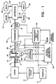
- FIG. 1 illustrates in schematic form the drive train of a motor vehicle including the automatic clutch controller of the present invention.
- the motor vehicle includes engine 10 as a source of motive power.
- engine 10 would be a diesel internal combustion engine.
- Throttle filter 12 filters the throttle signal supplied to engine 10 by supplying a ramped throttle signal upon receipt of a step throttle increase via throttle 11.
- Engine 10 produces torque on engine shaft 15.
- Engine speed sensor 13 detects the rotational velocity of engine shaft 15.
- the actual site of rotational velocity detection by engine speed sensor may be at the engine flywheel.
- Engine speed sensor 13 is preferably a multitooth wheel whose tooth rotation is detected by a magnetic sensor.
- Friction clutch 20 includes fixed plate 21 and movable plate 23 that are capable of full or partial engagement.
- Fixed plate 21 may be embodied by the engine flywheel.
- Friction clutch 20 couples torque from engine shaft 15 to transmission input shaft 25 corresponding to the degree of engagement between fixed plate 21 and movable plate 23. Note that while Figure 1 illustrates only a single pair of fixed and movable plates, those skilled in the art would realize that clutch 20 could include multiple pairs of such plates.
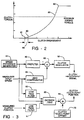
- FIG. 1 A typical torque verses clutch position function is illustrated in Figure 2.
- Clutch torque/position curve 80 is initially zero for a range of engagements before initial touch point 81. Clutch torque rises monotonically with increasing clutch engagement. In the example illustrated in Figure 2, clutch torque rises slowly at first and then more steeply until the maximum clutch torque is reached upon full engagement at point 82.
- the typical clutch design calls for the maximum clutch torque upon full engagement to be about 1.5 times the maximum engine torque. This ensures that clutch 20 can transfer the maximum torque produced by engine 10 without slipping.
- Clutch actuator 27 is coupled to movable plate 23 for control of clutch 20 from disengagement through partial engagement to full engagement.
- Clutch actuator 27 may be an electrical, hydraulic or pneumatic actuator and may be position or pressure controlled.
- Clutch actuator 27 controls the degree of clutch engagement according to a clutch engagement signal from clutch actuation controller 60.
- clutch actuator 27 is a closed loop controller.
- Clutch actuator 27 controls the degree of clutch engagement to cause the measured clutch position from clutch position sensor 29 to follow the clutch engagement signal.
- the touch point determination preferably employs the measured clutch position from clutch position sensor 29.
- clutch actuator 27 may be pressure controlled by a clutch actuation signal corresponding to the desired clutch pressure and employ clutch pressure feedback measured by a clutch pressure sensor.
- Transmission input speed sensor 31 senses the rotational velocity of transmission input shaft 25, which is the input to transmission 30.
- Transmission 30 provides selectable drive ratios to drive shaft 35 under the control of transmission shift controller 33.
- Drive shaft 35 is coupled to differential 40.
- Transmission output speed sensor 37 senses the rotational velocity of drive shaft 35.
- Transmission input speed sensor 31 and transmission output speed sensor 37 are preferably constructed in the same manner as engine speed sensor 13. In the preferred embodiment of the present invention, in which the motor vehicle is a large truck, differential 40 drives four axle shafts 41 to 44 that are in turn coupled to respective wheels 51 to 54.
- Transmission shift controller 33 receives input signals from throttle 11, engine speed sensor 13, transmission input speed sensor 31 and transmission output speed sensor 37. Transmission shift controller 33 generates gear select signals for control of transmission 30 and clutch engage/disengage signals coupled to clutch actuation controller 60. Transmission shift controller 33 preferably changes the final gear ratio provided by transmission 30 corresponding to the throttle setting, engine speed, transmission input speed and transmission output speed. Transmission shift controller 33 provides respective engage and disengage signals to clutch actuation controller 60 depending on whether friction clutch 20 should be engaged or disengaged. Transmission shift controller also transmits a gear signal to clutch actuation controller 60. This gear signal permits recall of the set of coefficients corresponding to the selected gear. Transmission shift controller 33 preferably briefly engages inertial brake 29 during upshifts.
- transmission shift controller 33 forms no part of the present invention and will not be further described.
- Clutch actuation controller 60 provides a clutch engagement signal to clutch actuator 27 for controlling the position of movable plate 23. This controls the amount of torque transferred by clutch 20 according to clutch torque/position curve 80 of Figure 2.
- Clutch actuation controller 60 operates under the control of transmission shift controller 33.
- Clutch actuation controller 60 controls the movement of moving plate 23 from disengagement to at least partial engagement or full engagement upon receipt of the engage signal from transmission shift controller 33.
- the clutch engagement signal will indicate a desired clutch position.
- Clutch actuator 27 preferably includes a closed loop control system employing the measured clutch position from clutch position sensor 29 for controlling movable plate 23 to this desired position.
- clutch engagement signal may represent a desired clutch pressure with clutch actuator 27 providing closed loop control to this desired pressure.
- clutch actuator 27 may be feasible for clutch actuator 27 to operate in an open loop fashion. The exact details of clutch actuator 27 are not crucial to this invention and will not be further discussed.
- Clutch actuation controller 60 preferably generates a predetermined open loop clutch disengagement signal for a ramped out disengagement of clutch 20 upon receipt of the disengage signal from transmission shift controller 33. No adverse oscillatory responses are anticipated for this predetermined open loop disengagement of clutch 20.
- clutch actuation controller 60 The control function of clutch actuation controller 60 is needed only for clutch positions between touch point 81 and full engagement. Clutch engagement less than that corresponding to touch point 81 provide no possibility of torque transfer because clutch 20 is fully disengaged.
- the present invention is a manner of detection of the clutch position corresponding to touch point 81. Upon receipt of the engage signal from transmission shift controller 33, clutch actuation controller 60 preferably rapidly advances clutch 20 to a point corresponding to touch point 81. This sets the zero of the clutch engagement control at touch point 81. Thereafter the clutch engagement is controlled by the control function of clutch actuation controller 60.
- FIG 3 illustrates schematically the determination of the touch point for clutch 20. This process is preferably a subset of the control function of clutch actuation controller 60. Determination of the touch point involves putting transmission 30 in neutral and applying inertial brake 29. Clutch 20 is progressively engaged while engine 10 is idling until the transmission input speed reaches a predetermined fraction of the engine idle speed. This degree of clutch engagement, corresponding to point 83 of Figure 2, transfers torque through clutch 20 to overcome the slight braking torque of inertial brake 29. A small, fixed offset 85 is subtracted from this degree of clutch engagement to determine the touch point 81.
- the touch point determination process begins with setting the proper initial conditions. These initial conditions include engine 10 idling, transmission 30 in neutral and inertial brake 29 engaged. Inertial brake 29 is normally present to aid in matching the rotational speed of transmission input shaft 25 to that of drive shaft 35 during upshifts. Because clutch 20 is disengaged during the shift the amount of braking needed is very small. Inertial brake 29 need only develop a braking torque of about 5% of the idling engine torque.
- Speed reference generator 61 generates a reference speed signal.
- This reference speed signal should correspond to about 40% to 60% of the engine idle speed. This reference speed signal must be less than the engine idle speed because the touch point determination requires clutch slippage while engine 10 idles.
- the speed reference signal is filtered via prefilter 62. Prefilter 62 is provided to prevent the application of a step function speed reference signal to the control process.
- An error speed signal is formed in algebraic summer 63.
- the error speed signal is the difference between the speed reference signal filtered by prefilter 62 minus a filtered input speed signal.
- Transmission input speed sensor 31 generates a transmission input speed signal corresponding to the rotational speed of the transmission input shaft 25.
- a lead compensator 64 filters the transmission input speed signal prior to formation of the difference.
- the speed error signal drives clutch regulator 65, which produces a clutch engagement signal for application to clutch actuator 27.
- clutch actuator 27 engages clutch 20 to a degree corresponding to the clutch actuation signal. Because the degree of clutch engagement determines the amount of torque coupled to transmission input shaft 25 and hence the measured transmission input speed, this forms a feedback system. Selection of the reference speed signal less than the engine idle speed ensures that clutch 20 slips when the speed error signal is driven to zero. The amount of torque required to overcome the braking torque of inertial brake 29 is so small that it does not stall engine 10.
- Decision logic unit 68 makes the clutch touch point determination.
- Decision logic unit 68 receives the measured transmission input speed signal filtered via low pass filter 66.
- Decision logic unit 68 also receives the measured clutch position signal from clutch position sensor 29 filtered via low pass filter 67.
- decision logic unit 68 receives the reference speed signal from speed reference generator 61.
- Decision logic unit 68 determines when a steady state is reached by comparing the filtered input speed signal with the reference speed signal. Steady state is defined as when the filtered input speed signal is within a predetermined fraction, such as 4%, of the reference speed signal. When this state is reached, decision logic unit 68 determines point 83 as the filtered measured clutch position signal.
- a second algebraic summer 69 determines the clutch position for touch point 81.
- Clutch touch point offset generator 70 generates a clutch touch point offset signal corresponding to the distance 85 shown in Figure 2. This amount is fixed for a particular vehicle and depends upon the clutch torque/position curve 80 and the braking torque of inertial brake 29. In the preferred embodiment of this invention this clutch touch point offset signal is 6.8% of the full travel of clutch 20.
- Second algebraic summer 69 forms a clutch touch point signal corresponding to the difference between the filtered measured clutch position signal from decision logic unit 68 minus the clutch touch point offset signal.
- Figure 4 illustrates an alternative embodiment of this invention. This alternative may be used when no measurement of the degree of clutch engagement is available.
- Low pass filter 71 which is similar to low pass filter 67 illustrated in Figure 3, filters the clutch engagement signal from clutch regulator 65. Since this signal will be available, and because clutch actuator 27 provides clutch engagement corresponding to this signal, it may be used as the measure of clutch engagement.
- Decision logic unit 68 determines when the filtered input speed signal is within 4% of the reference speed signal. When this state is reached, decision logic unit 68 determines point 83 as the filtered clutch engagement signal.
- Other portions of the embodiment of Figure 4 operate as previously described in conjunction with Figure 3.
- Clutch actuation controller 60 is preferably realized via a microcontroller circuit.
- Inputs corresponding to the engine speed, the transmission input speed, the throttle setting and clutch position must be in digital form. These input signals are preferably sampled at a rate consistent with the rate of operation of the microcontroller and fast enough to provide the desired control.
- the engine speed, transmission input speed and transmission output speed are preferably detected via multitooth wheels whose teeth rotation is detected by magnetic sensors.
- the pulse trains detected by the magnetic sensors are counted during predetermined intervals. The respective counts are directly proportional to the measured speed. For proper control the sign of the transmission input speed signal must be negative if the vehicle is moving backwards.
- the throttle setting and clutch position are preferably detected via analog sensors such as potentiometers. These analog signals are digitized via an analog-to-digital converter for use by the microcontroller.
- the microcontroller executes the processes illustrated in Figures 3 and 4 by discrete difference equations in a manner known in the art. The control processes illustrated in Figure 3 and 4 should therefore be regarded as an indication of how to program the microcontroller embodying the invention rather than discrete hardware. It is feasible for the same microcontroller, if of sufficient capacity and properly programmed, to act as both clutch actuation controller 60, including the clutch point determination of this invention, and as transmission shift controller 33. It is believed that an Intel 80C196 microcontroller has sufficient computation capacity to serve in this manner.
- the elements of Figures 3 and 4 are preferably implemented via discrete difference equations in a microcontroller.
- the numerical values in the descrete difference equations are a function of the processor sampling rate. The particular values given below are based upon a sampling rate of 100KHz. A lower sampling rate is feasible, which would require different coefficient values to achieve the same filter response. Adjustment of these coefficients for the sampling rate is within the ordinary skill in the art.
- CEng i CEng i-1 + SErr i - 0.98 SErr i-1
- CEng i-1 is the immediately preceding value of the clutch engagement signal
- SErr i is the current value of the speed error signal
- SErr i-1 is the immediately preceding value of the speed error signal.
- This technique provides an advantageous determination of the touch point.
- This technique is based upon a measure of clutch engagement which transfers a known, small torque. Because the transmission is in the neutral position, there are no other torques applied to transmission input shaft 25 and thus no disturbing forces. By measuring the clutch engagement which transfers this known, small torque the touch point may be more reliably estimated than looking for the initial torque transfer point. The feedback system ensures that the degree of engagement that transfers this small torque is reliably reached. This cannot be done as easily at the initial torque transfer point. Additionally, the inertial brake and the clutch engagement sensor are generally already provided in the base system, thus no additional hardware is required.
- the amended system is the same as that of Figure 3 except for the addition of a touch point memory circuit 90 and an initialization circuit 92.
- the touch point memory 90 has an input coupled to the output of the summer 69 and stores the most recent of the previously determined touch points, or even several of the most recent touch points for determination of a running average.
- the memory preferably comprises a portion of the system microcontroller memory.
- the initialization circuit 92 is coupled to the memory 90 and the clutch regulator 65 and calculates an initial clutch position IP based on one or more of the recent known touch points.
- the initial clutch position IP must be sufficiently above the previous touch point to assure that it is also above the current touch point so that further release movement of the clutch can be used to find the touch point.
- the initial clutch position may, for example, be the previous touch point plus a fixed increment.
- a signal is sent from the initializer 92 to the clutch regulator 65 to force the clutch to the position IP.
- the previously described clutch control based on the difference between the measured input speed and the reference speed, takes over to gradually move to the point 83 or somewhat below point 83.
- the clutch touch point offset is applied as for the Figure 3 system to determine the actual touch point, but the offset may have a smaller value.
Applications Claiming Priority (2)
| Application Number | Priority Date | Filing Date | Title |
|---|---|---|---|
| US08/126,107 US5337868A (en) | 1992-01-02 | 1993-09-23 | Touch point identification for automatic clutch controller |
| US126107 | 1993-09-23 |
Publications (2)
| Publication Number | Publication Date |
|---|---|
| EP0645277A1 true EP0645277A1 (fr) | 1995-03-29 |
| EP0645277B1 EP0645277B1 (fr) | 1997-12-10 |
Family
ID=22423025
Family Applications (1)
| Application Number | Title | Priority Date | Filing Date |
|---|---|---|---|
| EP94306940A Expired - Lifetime EP0645277B1 (fr) | 1993-09-23 | 1994-09-21 | Détection du point du contact d'un embrayage |
Country Status (11)
| Country | Link |
|---|---|
| US (1) | US5337868A (fr) |
| EP (1) | EP0645277B1 (fr) |
| JP (1) | JP3569874B2 (fr) |
| KR (1) | KR100329494B1 (fr) |
| AT (1) | ATE160974T1 (fr) |
| CA (1) | CA2132655C (fr) |
| CZ (1) | CZ290074B6 (fr) |
| DE (1) | DE69407243T2 (fr) |
| ES (1) | ES2111254T3 (fr) |
| RU (1) | RU2199448C2 (fr) |
| ZA (1) | ZA947458B (fr) |
Cited By (7)
| Publication number | Priority date | Publication date | Assignee | Title |
|---|---|---|---|---|
| WO1997017552A1 (fr) * | 1995-11-03 | 1997-05-15 | Robert Bosch Gmbh | Systeme de commande d'embrayage automatique |
| FR2742480A1 (fr) * | 1995-12-15 | 1997-06-20 | Renault | Procede de commande de l'alimentation en carburant d'un moteur a combustion interne |
| FR2751388A1 (fr) * | 1996-07-19 | 1998-01-23 | Renault | Procede d'apprentissage du fonctionnement d'un embrayage mecanique |
| FR2756228A1 (fr) * | 1996-11-22 | 1998-05-29 | Renault | Procede d'apprentissage du point de debut de passage de couple d'un embrayage |
| EP1177932A3 (fr) * | 2000-08-02 | 2006-12-06 | Toyota Jidosha Kabushiki Kaisha | Appareil de régulation automatique du démarrage d'un moteur à combustion interne et détecteur de l'état d'un embrayage |
| WO2007014636A1 (fr) * | 2005-08-03 | 2007-02-08 | Daimlerchrysler Ag | Procede et dispositif de commande permettant de regler une vitesse de rotation d'un arbre d'une boite de vitesses a engrenages |
| CN104769332A (zh) * | 2012-10-31 | 2015-07-08 | 丰田自动车株式会社 | 车辆的行驶控制装置 |
Families Citing this family (55)
| Publication number | Priority date | Publication date | Assignee | Title |
|---|---|---|---|---|
| US5393274A (en) * | 1993-07-19 | 1995-02-28 | Eaton Corporation | Touch point identification algorithm for automatic clutch controller |
| US5439428A (en) * | 1994-02-22 | 1995-08-08 | Eaton Corporation | Method and apparatus for robust automatic clutch control with pid regulation |
| GB2291199A (en) * | 1994-07-09 | 1996-01-17 | Rolls Royce Plc | Steady state sensor |
| DE4434111A1 (de) * | 1994-09-23 | 1996-03-28 | Kongsberg Automotive Technolog | Steuerung für eine automatisch betätigte Kupplung |
| JP3237419B2 (ja) * | 1994-10-21 | 2001-12-10 | トヨタ自動車株式会社 | 車両用クラッチ制御装置 |
| GB9421350D0 (en) * | 1994-10-24 | 1994-12-07 | Eaton Corp | Automated clutch control and calibration |
| US5630773A (en) | 1996-02-02 | 1997-05-20 | Eaton Corporation | Method and apparatus for slip mode control of automatic clutch |
| GB9617930D0 (en) | 1996-08-28 | 1996-10-09 | Eaton Corp | Actuator system for vehicular automated clutches with electric motor actuator and pressurized override |
| DE19639289C1 (de) | 1996-09-25 | 1997-11-20 | Daimler Benz Ag | Automatisch gesteuerte Kupplung |
| GB9626527D0 (en) * | 1996-12-20 | 1997-02-05 | Ap Kongsberg Holdings Ltd | Clutches |
| US6050379A (en) * | 1998-07-10 | 2000-04-18 | Chrysler Corporation | Algorithm for electro-mechanical clutch actuator |
| US6022295A (en) * | 1998-11-12 | 2000-02-08 | Eaton Corporation | Touch point identification for vehicle master clutch |
| US5980428A (en) * | 1998-11-13 | 1999-11-09 | Eaton Corporation | Vehicle launch automated master clutch control |
| US6071211A (en) * | 1998-11-18 | 2000-06-06 | Eaton Corporation | Idle drive torque control for automated vehicle master clutch |
| AU4390800A (en) | 1999-03-15 | 2000-10-04 | Luk Lamellen Und Kupplungsbau Beteiligungs Kg | Control system for automatically controlling a clutch during starting |
| DE10037544A1 (de) * | 1999-08-31 | 2001-03-01 | Luk Lamellen & Kupplungsbau | Getriebe |
| DE19951527C1 (de) * | 1999-10-26 | 2001-06-13 | Siemens Ag | Steuerung für eine automatisch betätigte Kupplung eines Kraftfahrzeugs und Verfahren zum Steuern einer automatisch betätigten Kupplung |
| GB2361980A (en) | 2000-05-05 | 2001-11-07 | Eaton Corp | Dry clutch control system using idle drive torque so as to provide vehicle crawl speed |
| DE10191985D2 (de) * | 2000-05-17 | 2003-07-03 | Luk Lamellen & Kupplungsbau | Getriebe mit Kupplung sowie Verfahren zum Betreiben einer Kupplung |
| DE10038331A1 (de) * | 2000-08-05 | 2002-02-14 | Daimler Chrysler Ag | Verfahren zum Erfassen des Betriebszustandes einer reibschlüssigen Kupplung |
| DE10060642C2 (de) | 2000-12-06 | 2003-04-30 | Siemens Ag | Steuerug für eine automatisch betätigte Kupplung |
| DE10159267B4 (de) * | 2000-12-14 | 2015-01-15 | Schaeffler Technologies Gmbh & Co. Kg | Verfahren zur Lageregelung eines Kupplungsaktuators |
| DE10116544C1 (de) * | 2001-04-03 | 2002-06-27 | Siemens Ag | Betätigungssystem für die Kupplung eines mit einem automatisierten Schaltgetriebe versehenen Kraftfahrzeugantriebs und Verfahren zum Steuern eines solchen Betätigungssystems |
| DE10228709A1 (de) * | 2001-07-12 | 2003-02-13 | Luk Lamellen & Kupplungsbau | Verfahren zum Adaptieren der Einstellung einer Kupplung in einem unkonventionellen Antriebsstrang eines Fahrzeugs |
| DE10306934A1 (de) * | 2003-02-19 | 2004-09-02 | Zf Friedrichshafen Ag | Verfahren zur Anlegepunktbestimmung der Kupplung eines automatisierten Schaltgetriebes |
| FR2859258B1 (fr) * | 2003-08-29 | 2006-02-24 | Renault Sa | Procede pour selectioner une loi de commande du systeme de pilotage d'un embrayage en determinant trois points de fonctionnement |
| US20050109141A1 (en) * | 2003-11-25 | 2005-05-26 | Devore James H. | Automated mechanical transmission system |
| US7048106B2 (en) * | 2004-03-26 | 2006-05-23 | Cnh America Llc | Power take-off control system and method |
| DE102006042356A1 (de) * | 2006-09-08 | 2008-03-27 | Zf Friedrichshafen Ag | Verfahren zur Detektierung des Anlegepunktes einer Kupplung, insbesondere einer nassen Anfahrkupplung |
| DE102007013495A1 (de) | 2007-03-21 | 2008-09-25 | Zf Friedrichshafen Ag | Verfahren zur Steuerung einer automatisierten Reibungskupplung eines Doppelkupplungsgetriebes |
| DE102007022792A1 (de) * | 2007-05-11 | 2008-11-20 | Knorr-Bremse Systeme für Nutzfahrzeuge GmbH | Kupplungsstellvorrichtung für ein manuelles Schaltgetriebe eines Fahrzeugs und entsprechendes Steuerungsverfahren |
| FR2918334B1 (fr) * | 2007-07-06 | 2009-09-11 | Renault Sas | Procede de traitement de donnees dans un dispositif d'assistance aux manoeuvres en cote d'un vehicule automobile |
| DE102007038150B4 (de) * | 2007-08-13 | 2010-04-29 | Magna Powertrain Ag & Co Kg | Steuerverfahren für Kupplungsanordnung |
| DE102007050301B4 (de) | 2007-10-22 | 2021-10-21 | Robert Bosch Gmbh | Verfahren und Vorrichtung zum Erkennen einer Fehlfunktion einer Kupplung |
| DE102008000341A1 (de) | 2008-02-19 | 2009-08-20 | Zf Friedrichshafen Ag | Verfahren zur Steuerung eines Planeten-Automatgetriebes |
| JP5162767B2 (ja) * | 2008-03-28 | 2013-03-13 | 本田技研工業株式会社 | クラッチ制御装置 |
| US8738256B2 (en) * | 2008-07-01 | 2014-05-27 | Eaton Corporation | Automatic calibration of the torque transfer touch point in an electrically actuated clutch in a hybrid vehicle |
| SE534255C2 (sv) * | 2009-09-01 | 2011-06-21 | Scania Cv Ab | Anordning och förfarande för att utföra ett växlingssteg hos ett fordon |
| SE534111C2 (sv) * | 2009-09-14 | 2011-05-03 | Scania Cv Ab | Metod och system för styrning av en koppling |
| SE534245C2 (sv) * | 2009-09-14 | 2011-06-14 | Scania Cv Ab | Metod och system för bestämning av kontaktpunkten för en koppling vid ett fordon |
| DE102010039172B4 (de) * | 2010-08-11 | 2023-12-07 | Zf Friedrichshafen Ag | Verfahren zur Ermittlung eines Anlegebetätigungsdruckwertes eines reibschlüssigen Schaltelements |
| KR101371461B1 (ko) * | 2012-09-06 | 2014-03-10 | 기아자동차주식회사 | 하이브리드 차량의 엔진클러치의 토크전달 시작점 학습 제어 방법 및 시스템 |
| KR101416375B1 (ko) * | 2012-12-18 | 2014-07-08 | 기아자동차 주식회사 | 하이브리드 차량의 엔진클러치의 학습 주기 설정 방법 및 시스템 |
| DE112014006208B4 (de) * | 2014-01-20 | 2024-03-21 | Schaeffler Technologies AG & Co. KG | Verfahren zur Steuerung einer Reibungskupplung |
| CN107250589B (zh) * | 2014-11-19 | 2019-03-08 | Gkn汽车有限公司 | 用于使离合器运行的方法和机动车 |
| EP3221609B1 (fr) * | 2014-11-19 | 2021-07-07 | Dana Automotive Systems Group, LLC | Procédé de régulation de la force d'embrayage dans un embrayage |
| CN104879491B (zh) * | 2015-04-28 | 2017-03-08 | 上海汽车变速器有限公司 | 同步器同步点辨识方法及系统 |
| DE102015222007B4 (de) | 2015-11-09 | 2020-07-09 | Audi Ag | Verfahren zum Betreiben einer elektrohydraulischen Getriebekupplung eines Kraftfahrzeugs, Steuervorrichtung für eine elektrohydraulische Getriebekupplung eines Kraftfahrzeugs sowie Kraftfahrzeug mit einer elektrohydraulischen Getriebekupplung |
| KR101847641B1 (ko) | 2016-07-25 | 2018-05-28 | 현대오트론 주식회사 | 클러치 터치포인트 탐색 방법 |
| DE102017109403B4 (de) | 2017-05-03 | 2023-06-22 | Schaeffler Technologies AG & Co. KG | Verfahren und Vorrichtung zur Absolutpositionsbestimmung eines sich um eine Drehachse drehenden Bauteiles eines Aktors, insbesondere eines Kupplungsaktors |
| RU196789U1 (ru) * | 2019-08-23 | 2020-03-16 | Леонид Александрович Румянцев | Устройство управления сцеплением нормально разомкнутого типа |
| CN112432787B (zh) * | 2019-08-26 | 2023-10-27 | 上海汽车集团股份有限公司 | 单向离合器有效性确定方法及装置 |
| CN110595769B (zh) * | 2019-09-20 | 2021-03-12 | 北华大学 | 一种联轴器可靠性试验系统 |
| CN113696882B (zh) * | 2021-09-30 | 2023-12-15 | 潍柴动力股份有限公司 | 一种离合器滑摩点的位置的确定方法、装置及汽车 |
| CN114151469B (zh) * | 2021-12-01 | 2023-09-26 | 中国第一汽车股份有限公司 | 离合器半结合点位置自学习控制方法、装置、设备及介质 |
Citations (7)
| Publication number | Priority date | Publication date | Assignee | Title |
|---|---|---|---|---|
| GB2170571A (en) * | 1985-01-31 | 1986-08-06 | Eaton Corp | Automatic clutch control |
| EP0320261A1 (fr) * | 1987-12-11 | 1989-06-14 | Isuzu Motors Limited | Dispositif automatique de contrôle d'un embrayage |
| EP0385629A2 (fr) * | 1989-03-02 | 1990-09-05 | Eaton Corporation | Méthode et système d'actualisation de la valeur de commande indiquant le point de commencement d'engagement de l'embrayage principal |
| EP0392762A2 (fr) * | 1989-04-12 | 1990-10-17 | Diesel Kiki Co. Ltd. | Méthode de correction des données utilisées pendant une opération de commande d'embrayage |
| FR2645805A1 (fr) * | 1989-04-17 | 1990-10-19 | Luk Lamellen & Kupplungsbau | Procede de commande d'un embrayage a friction automatise agissant entre un moteur d'entrainement et une transmission, appareillage pour la mise en oeuvre du procede, et regulation associee d'un embrayage a friction |
| EP0550222A2 (fr) * | 1992-01-02 | 1993-07-07 | Eaton Corporation | Détection du point de contact pour dispositif de commande d'un embrayage automatique |
| US5337874A (en) * | 1993-03-19 | 1994-08-16 | Eaton Corporation | Method/system for determining clutch touch point |
Family Cites Families (16)
| Publication number | Priority date | Publication date | Assignee | Title |
|---|---|---|---|---|
| US3297926A (en) * | 1961-10-19 | 1967-01-10 | Gen Motors Corp | Vehicle propulsion and control system |
| US4081065A (en) * | 1976-12-23 | 1978-03-28 | Smyth Robert Ralston | Controlled power clutch |
| US4457411A (en) * | 1980-06-02 | 1984-07-03 | Mitsubishi Jidosha Kogyo Kabushiki Kaisha | Torque transmission device |
| US4576265A (en) * | 1982-10-22 | 1986-03-18 | Nissan Motor Co., Ltd. | Control system for hydraulic automatic clutch |
| DE3404156A1 (de) * | 1984-02-07 | 1985-08-14 | Daimler-Benz Ag, 7000 Stuttgart | Einrichtung zur automatischen betaetigung einer kupplung von fahrzeugen waehrend des anfahrens |
| DE3590104T (de) * | 1984-03-16 | 1986-06-05 | Mitsubishi Jidosha Kogyo K.K., Tokio/Tokyo | Getriebeautomatik für Fahrzeuge |
| JPS61196831A (ja) * | 1985-02-26 | 1986-09-01 | Diesel Kiki Co Ltd | 内燃機関車輛用自動発進制御装置 |
| US4674609A (en) * | 1985-06-03 | 1987-06-23 | Borg-Warner Corporation | Torsional vibration dampening system |
| US4768635A (en) * | 1985-11-25 | 1988-09-06 | Honda Giken Kogyo Kabushiki Kaisha | Control for the clutch of a fluid torque converter in a vehicular transmission |
| US4792902A (en) * | 1985-12-12 | 1988-12-20 | Ford Motor Company | Engine ignition timing for a clutch engagement control system |
| US4766967A (en) * | 1985-12-27 | 1988-08-30 | Eaton Corporation | Oscillation control system for electric motor drive |
| JPH0796377B2 (ja) * | 1986-04-24 | 1995-10-18 | 富士重工業株式会社 | 車両用自動クラツチの制御装置 |
| US4724939A (en) * | 1986-07-17 | 1988-02-16 | General Motors Corporation | Closed loop clutch slip control system with turbine roughness control |
| US4993527A (en) * | 1988-04-29 | 1991-02-19 | Chrysler Corporation | Method of determining and controlling the lock-up of a torque converter in an electronic automatic transmission system |
| US5170868A (en) * | 1990-10-31 | 1992-12-15 | Suzuki Motor Corporation | Automatic starting clutch control method |
| US5293316A (en) * | 1991-10-07 | 1994-03-08 | Eaton Corporation | Closed loop launch and creep control for automatic clutch |
-
1993
- 1993-09-23 US US08/126,107 patent/US5337868A/en not_active Expired - Lifetime
-
1994
- 1994-09-21 EP EP94306940A patent/EP0645277B1/fr not_active Expired - Lifetime
- 1994-09-21 ES ES94306940T patent/ES2111254T3/es not_active Expired - Lifetime
- 1994-09-21 DE DE69407243T patent/DE69407243T2/de not_active Expired - Fee Related
- 1994-09-21 AT AT94306940T patent/ATE160974T1/de not_active IP Right Cessation
- 1994-09-22 RU RU94034118/28A patent/RU2199448C2/ru not_active IP Right Cessation
- 1994-09-22 CZ CZ19942323A patent/CZ290074B6/cs not_active IP Right Cessation
- 1994-09-22 CA CA002132655A patent/CA2132655C/fr not_active Expired - Fee Related
- 1994-09-23 ZA ZA947458A patent/ZA947458B/xx unknown
- 1994-09-23 KR KR1019940023984A patent/KR100329494B1/ko not_active IP Right Cessation
- 1994-09-24 JP JP25442294A patent/JP3569874B2/ja not_active Expired - Fee Related
Patent Citations (7)
| Publication number | Priority date | Publication date | Assignee | Title |
|---|---|---|---|---|
| GB2170571A (en) * | 1985-01-31 | 1986-08-06 | Eaton Corp | Automatic clutch control |
| EP0320261A1 (fr) * | 1987-12-11 | 1989-06-14 | Isuzu Motors Limited | Dispositif automatique de contrôle d'un embrayage |
| EP0385629A2 (fr) * | 1989-03-02 | 1990-09-05 | Eaton Corporation | Méthode et système d'actualisation de la valeur de commande indiquant le point de commencement d'engagement de l'embrayage principal |
| EP0392762A2 (fr) * | 1989-04-12 | 1990-10-17 | Diesel Kiki Co. Ltd. | Méthode de correction des données utilisées pendant une opération de commande d'embrayage |
| FR2645805A1 (fr) * | 1989-04-17 | 1990-10-19 | Luk Lamellen & Kupplungsbau | Procede de commande d'un embrayage a friction automatise agissant entre un moteur d'entrainement et une transmission, appareillage pour la mise en oeuvre du procede, et regulation associee d'un embrayage a friction |
| EP0550222A2 (fr) * | 1992-01-02 | 1993-07-07 | Eaton Corporation | Détection du point de contact pour dispositif de commande d'un embrayage automatique |
| US5337874A (en) * | 1993-03-19 | 1994-08-16 | Eaton Corporation | Method/system for determining clutch touch point |
Cited By (9)
| Publication number | Priority date | Publication date | Assignee | Title |
|---|---|---|---|---|
| WO1997017552A1 (fr) * | 1995-11-03 | 1997-05-15 | Robert Bosch Gmbh | Systeme de commande d'embrayage automatique |
| FR2742480A1 (fr) * | 1995-12-15 | 1997-06-20 | Renault | Procede de commande de l'alimentation en carburant d'un moteur a combustion interne |
| FR2751388A1 (fr) * | 1996-07-19 | 1998-01-23 | Renault | Procede d'apprentissage du fonctionnement d'un embrayage mecanique |
| FR2756228A1 (fr) * | 1996-11-22 | 1998-05-29 | Renault | Procede d'apprentissage du point de debut de passage de couple d'un embrayage |
| EP1177932A3 (fr) * | 2000-08-02 | 2006-12-06 | Toyota Jidosha Kabushiki Kaisha | Appareil de régulation automatique du démarrage d'un moteur à combustion interne et détecteur de l'état d'un embrayage |
| WO2007014636A1 (fr) * | 2005-08-03 | 2007-02-08 | Daimlerchrysler Ag | Procede et dispositif de commande permettant de regler une vitesse de rotation d'un arbre d'une boite de vitesses a engrenages |
| US8062181B2 (en) | 2005-08-03 | 2011-11-22 | Daimler Ag | Method and control device for adjusting a rotational speed of a shaft of a gear change transmission |
| CN104769332A (zh) * | 2012-10-31 | 2015-07-08 | 丰田自动车株式会社 | 车辆的行驶控制装置 |
| CN104769332B (zh) * | 2012-10-31 | 2016-12-14 | 丰田自动车株式会社 | 车辆的行驶控制装置 |
Also Published As
| Publication number | Publication date |
|---|---|
| DE69407243D1 (de) | 1998-01-22 |
| KR950008196A (ko) | 1995-04-17 |
| ZA947458B (en) | 1996-03-25 |
| ATE160974T1 (de) | 1997-12-15 |
| RU94034118A (ru) | 1996-07-27 |
| DE69407243T2 (de) | 1998-07-09 |
| ES2111254T3 (es) | 1998-03-01 |
| RU2199448C2 (ru) | 2003-02-27 |
| CA2132655A1 (fr) | 1995-03-24 |
| US5337868A (en) | 1994-08-16 |
| CZ290074B6 (cs) | 2002-05-15 |
| EP0645277B1 (fr) | 1997-12-10 |
| CZ232394A3 (en) | 1995-04-12 |
| JP3569874B2 (ja) | 2004-09-29 |
| KR100329494B1 (ko) | 2002-11-13 |
| CA2132655C (fr) | 1999-05-11 |
| JPH07158667A (ja) | 1995-06-20 |
Similar Documents
| Publication | Publication Date | Title |
|---|---|---|
| EP0645277B1 (fr) | Détection du point du contact d'un embrayage | |
| EP0550222B1 (fr) | Détection du point de contact pour dispositif de commande d'un embrayage automatique | |
| EP0635391B1 (fr) | Algorithme d'identification du point de contact pour dispositif de commande d'embrayage automatique | |
| EP0601729B1 (fr) | Système de commande d'un moteur avec régulaton automatique de l'embrayage | |
| EP0601728B1 (fr) | Logique de régulation des modes d'un embrayage | |
| US5630773A (en) | Method and apparatus for slip mode control of automatic clutch | |
| CA2143061C (fr) | Methode et dispositif pour eliminer les oscillations provoquees par les embrayages, faisant appel a un regulateur p.i.d. | |
| EP0536932B1 (fr) | Régulation de démarrage et de rampage pour un embrayage automatique | |
| CA2079754C (fr) | Dispositif de controle asservi de l'engagement et du glissement a algorithme robuste pour embrayage automatique |
Legal Events
| Date | Code | Title | Description |
|---|---|---|---|
| PUAI | Public reference made under article 153(3) epc to a published international application that has entered the european phase |
Free format text: ORIGINAL CODE: 0009012 |
|
| AK | Designated contracting states |
Kind code of ref document: A1 Designated state(s): AT DE ES FR GB IT NL SE |
|
| 17P | Request for examination filed |
Effective date: 19950922 |
|
| 17Q | First examination report despatched |
Effective date: 19951018 |
|
| GRAG | Despatch of communication of intention to grant |
Free format text: ORIGINAL CODE: EPIDOS AGRA |
|
| GRAH | Despatch of communication of intention to grant a patent |
Free format text: ORIGINAL CODE: EPIDOS IGRA |
|
| GRAH | Despatch of communication of intention to grant a patent |
Free format text: ORIGINAL CODE: EPIDOS IGRA |
|
| GRAA | (expected) grant |
Free format text: ORIGINAL CODE: 0009210 |
|
| ITF | It: translation for a ep patent filed |
Owner name: STUDIO GLP S.R.L. |
|
| AK | Designated contracting states |
Kind code of ref document: B1 Designated state(s): AT DE ES FR GB IT NL SE |
|
| REF | Corresponds to: |
Ref document number: 160974 Country of ref document: AT Date of ref document: 19971215 Kind code of ref document: T |
|
| REF | Corresponds to: |
Ref document number: 69407243 Country of ref document: DE Date of ref document: 19980122 |
|
| REG | Reference to a national code |
Ref country code: ES Ref legal event code: FG2A Ref document number: 2111254 Country of ref document: ES Kind code of ref document: T3 |
|
| ET | Fr: translation filed | ||
| PLBE | No opposition filed within time limit |
Free format text: ORIGINAL CODE: 0009261 |
|
| STAA | Information on the status of an ep patent application or granted ep patent |
Free format text: STATUS: NO OPPOSITION FILED WITHIN TIME LIMIT |
|
| NLT2 | Nl: modifications (of names), taken from the european patent patent bulletin |
Owner name: EATON CORPORATION |
|
| 26N | No opposition filed | ||
| REG | Reference to a national code |
Ref country code: GB Ref legal event code: IF02 |
|
| PGFP | Annual fee paid to national office [announced via postgrant information from national office to epo] |
Ref country code: AT Payment date: 20050701 Year of fee payment: 12 |
|
| PGFP | Annual fee paid to national office [announced via postgrant information from national office to epo] |
Ref country code: NL Payment date: 20050808 Year of fee payment: 12 |
|
| PGFP | Annual fee paid to national office [announced via postgrant information from national office to epo] |
Ref country code: FR Payment date: 20050902 Year of fee payment: 12 |
|
| PGFP | Annual fee paid to national office [announced via postgrant information from national office to epo] |
Ref country code: ES Payment date: 20050919 Year of fee payment: 12 |
|
| PG25 | Lapsed in a contracting state [announced via postgrant information from national office to epo] |
Ref country code: AT Free format text: LAPSE BECAUSE OF NON-PAYMENT OF DUE FEES Effective date: 20060921 |
|
| PGFP | Annual fee paid to national office [announced via postgrant information from national office to epo] |
Ref country code: IT Payment date: 20060930 Year of fee payment: 13 |
|
| PG25 | Lapsed in a contracting state [announced via postgrant information from national office to epo] |
Ref country code: NL Free format text: LAPSE BECAUSE OF NON-PAYMENT OF DUE FEES Effective date: 20070401 |
|
| NLV4 | Nl: lapsed or anulled due to non-payment of the annual fee |
Effective date: 20070401 |
|
| REG | Reference to a national code |
Ref country code: FR Ref legal event code: ST Effective date: 20070531 |
|
| REG | Reference to a national code |
Ref country code: ES Ref legal event code: FD2A Effective date: 20060922 |
|
| PG25 | Lapsed in a contracting state [announced via postgrant information from national office to epo] |
Ref country code: ES Free format text: LAPSE BECAUSE OF NON-PAYMENT OF DUE FEES Effective date: 20060922 |
|
| PG25 | Lapsed in a contracting state [announced via postgrant information from national office to epo] |
Ref country code: FR Free format text: LAPSE BECAUSE OF NON-PAYMENT OF DUE FEES Effective date: 20061002 |
|
| PGFP | Annual fee paid to national office [announced via postgrant information from national office to epo] |
Ref country code: GB Payment date: 20080808 Year of fee payment: 15 |
|
| PGFP | Annual fee paid to national office [announced via postgrant information from national office to epo] |
Ref country code: DE Payment date: 20080930 Year of fee payment: 15 |
|
| PGFP | Annual fee paid to national office [announced via postgrant information from national office to epo] |
Ref country code: SE Payment date: 20080905 Year of fee payment: 15 |
|
| PG25 | Lapsed in a contracting state [announced via postgrant information from national office to epo] |
Ref country code: IT Free format text: LAPSE BECAUSE OF NON-PAYMENT OF DUE FEES Effective date: 20070921 |
|
| EUG | Se: european patent has lapsed | ||
| GBPC | Gb: european patent ceased through non-payment of renewal fee |
Effective date: 20090921 |
|
| PG25 | Lapsed in a contracting state [announced via postgrant information from national office to epo] |
Ref country code: DE Free format text: LAPSE BECAUSE OF NON-PAYMENT OF DUE FEES Effective date: 20100401 |
|
| PG25 | Lapsed in a contracting state [announced via postgrant information from national office to epo] |
Ref country code: GB Free format text: LAPSE BECAUSE OF NON-PAYMENT OF DUE FEES Effective date: 20090921 |
|
| PG25 | Lapsed in a contracting state [announced via postgrant information from national office to epo] |
Ref country code: SE Free format text: LAPSE BECAUSE OF NON-PAYMENT OF DUE FEES Effective date: 20090922 |