EP0644648B1 - Control method and apparatus and malefunction detection method and apparatus for AC motor - Google Patents
Control method and apparatus and malefunction detection method and apparatus for AC motor Download PDFInfo
- Publication number
- EP0644648B1 EP0644648B1 EP94114548A EP94114548A EP0644648B1 EP 0644648 B1 EP0644648 B1 EP 0644648B1 EP 94114548 A EP94114548 A EP 94114548A EP 94114548 A EP94114548 A EP 94114548A EP 0644648 B1 EP0644648 B1 EP 0644648B1
- Authority
- EP
- European Patent Office
- Prior art keywords
- value
- magnetizing current
- motor
- estimated
- obtaining
- Prior art date
- Legal status (The legal status is an assumption and is not a legal conclusion. Google has not performed a legal analysis and makes no representation as to the accuracy of the status listed.)
- Expired - Lifetime
Links
Images


Classifications
-
- H—ELECTRICITY
- H02—GENERATION; CONVERSION OR DISTRIBUTION OF ELECTRIC POWER
- H02P—CONTROL OR REGULATION OF ELECTRIC MOTORS, ELECTRIC GENERATORS OR DYNAMO-ELECTRIC CONVERTERS; CONTROLLING TRANSFORMERS, REACTORS OR CHOKE COILS
- H02P21/00—Arrangements or methods for the control of electric machines by vector control, e.g. by control of field orientation
- H02P21/14—Estimation or adaptation of machine parameters, e.g. flux, current or voltage
- H02P21/16—Estimation of constants, e.g. the rotor time constant
-
- H—ELECTRICITY
- H02—GENERATION; CONVERSION OR DISTRIBUTION OF ELECTRIC POWER
- H02P—CONTROL OR REGULATION OF ELECTRIC MOTORS, ELECTRIC GENERATORS OR DYNAMO-ELECTRIC CONVERTERS; CONTROLLING TRANSFORMERS, REACTORS OR CHOKE COILS
- H02P21/00—Arrangements or methods for the control of electric machines by vector control, e.g. by control of field orientation
- H02P21/50—Vector control arrangements or methods not otherwise provided for in H02P21/00- H02P21/36
-
- H—ELECTRICITY
- H02—GENERATION; CONVERSION OR DISTRIBUTION OF ELECTRIC POWER
- H02P—CONTROL OR REGULATION OF ELECTRIC MOTORS, ELECTRIC GENERATORS OR DYNAMO-ELECTRIC CONVERTERS; CONTROLLING TRANSFORMERS, REACTORS OR CHOKE COILS
- H02P29/00—Arrangements for regulating or controlling electric motors, appropriate for both AC and DC motors
- H02P29/02—Providing protection against overload without automatic interruption of supply
- H02P29/024—Detecting a fault condition, e.g. short circuit, locked rotor, open circuit or loss of load
- H02P29/0241—Detecting a fault condition, e.g. short circuit, locked rotor, open circuit or loss of load the fault being an overvoltage
-
- G—PHYSICS
- G01—MEASURING; TESTING
- G01R—MEASURING ELECTRIC VARIABLES; MEASURING MAGNETIC VARIABLES
- G01R31/00—Arrangements for testing electric properties; Arrangements for locating electric faults; Arrangements for electrical testing characterised by what is being tested not provided for elsewhere
- G01R31/34—Testing dynamo-electric machines
- G01R31/343—Testing dynamo-electric machines in operation
Definitions
- the present invention relates to a control method and apparatus for an AC motor that detects a primary resistance of the AC motor with excellent accuracy and to a malfunction detection method and apparatus that detects a malfunction by comparing estimated primary resistance values of each phase.
- Magnetic flux and torque of an AC motor can be controlled by resolving a current flowing through the AC motor into a magnetizing current component parallel to the magnetic flux and a torque current component perpendicular to the magnetic flux, and by controlling the magnetizing current and the torque current components independently. It is well known that the speed of the AC motor can be controlled highly accurately by the so-called transvector control method that treats the current of the AC motor as a vector consisting of two components.
- control constants based on the equivalent circuit constants are pre-set to a control apparatus.
- designed values of the motor constants are used as these control constants.
- control errors Variations of the motor constants during driving the motor also cause control errors.
- the transvector control method can not be applied when the constants of the motor already in service are unknown.
- the induced electromotive force is calculated by subtracting the voltage drop across the internal impedance of the motor from the terminal voltage of the motor.
- the voltage drop across the internal impedance of the motor is obtained by multiplying the magnetizing current component and a primary resistance value of the motor. Generated torque becomes insufficient especially when the motor is driven at low speed, because an appropriate output reference voltage value can not be calculated when the primary resistance value is different from the pre-set value.
- the method of calculating the primary resistance value by dividing output voltage by the phase current requires high precision detectors, because the prior art method is affected by the precision of the voltage and current detectors.
- the primary resistance value of a large capacity motor is small, even the high precision detectors would not improve accuracy of the measurements.
- induced electromotive force of the magnetizing inductance is added to the voltage drop across the primary resistance. Since decay time of the induced electromotive force is prolonged in an AC motor of large secondary time constant, for example a large capacity AC motor, it takes long time for the resistance value obtained by dividing output voltage by a current to reach a true primary resistance value.
- motor windings through which a current flows or semiconductor switching elements of the power converter are different depending on a phase angle of voltage applied to the AC motor. Since resistance values of the motor windings or the semiconductor switching elements show variations, the measured primary resistance value shows variation depending on phase angle difference which further causes a control error. In controlling the general-purpose AC motors, actual torque is not always used for further control of the AC motors.
- an object of the present invention is to provide a control method and apparatus that measures, without using high precision detectors, the primary resistance of an AC motor with high accuracy in a short time by eliminating the errors caused by the phase angle difference.
- Another object of the present invention is to provide a control method and apparatus that detects malfunctions such as breaking of wiring, open phases and three-phase unbalance of the AC motor or the power converting means.
- the control method obtains an estimated primary resistance R 1 # as a result of an integral operation or a proportional plus integral operation on the difference between a reference magnetizing current value I M * and a detected magnetizing current value I M .
- the voltage drop across the primary resistance is estimated by multiplying the estimated primary resistance value R 1 # and the reference magnetizing current value I M *.
- a reference magnetizing voltage value V M * is obtained by adding an amplified deviation of the reference magnetizing current value I M * from the detected magnetizing current value I M and the estimated voltage drop value.
- the reference magnetizing voltage value V M * is expressed by the following equation 1.
- the estimated primary resistance R 1 # is expressed by the following equation 2 or 3.
- K A is a proportional gain of an amplifying means
- K P a proportional gain of a proportional plus integral means
- K I an integral gain of an integral means or the proportional plus integral means.
- V M * K A (I M *-I M )+R 1 # ⁇ I M *
- R 1 # K I ⁇ (I M *-I M ) ⁇ dt
- R 1 # K p (I M *-I M )+K I ⁇ (I M *-I M ) ⁇ dt
- the estimated primary resistance value R 1 # increases when the deviation between the reference and detected magnetizing current values (I M *-I M ) is positive and R 1 # decreases when the deviation (I M *-I M ) is negative, the reference magnetizing voltage value V M * is corrected by equation 1. Therefore, when the deviation (I M *-I M ) decreases to zero, the estimated primary resistance value R 1 # coincides with the actual primary resistance value R 1 from equation 5.
- a control method obtains a total resistance value of the winding resistance of each phase, the wiring resistance between the power converting means and the AC motor, and the resistance of the switching elements of the power converting means by switching-on one switching element on the positive side and another switching element on the negative side (while avoiding pairs which cause an arm short circuit) and by measuring six sets of resistance values of two phases of the three-phase AC motor when a current is made to flow through the two phases.
- the most appropriate primary resistance value for the control is obtained by calculating a mean value of the total resistance values of all the phases.
- the control method determines in advance a reference magnetizing current pattern in which the reference magnetizing current value I M * decreases from an initial large value at the start of the AC motor to a predetermined value after a predetermined period of time has elapsed.
- the necessary time for estimating the primary resistance value is shortened, because an actual magnetizing current takes a large value immediately after the start of the AC motor, by which influence of the induced electromagnetic force on the voltage drop across the primary resistance is reduced.
- Yet another embodiment of the invention obtains a total resistance value of winding resistance of each phase, wiring resistance between the power converting means and the AC motor, and resistance of the switching elements of the power converting means, compares the resistance values of all the phases, and then detects malfunctions such as breaking of wire, open phases and three-phase unbalance of the AC motor or power converting means.
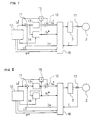
- FIG. 1 is a circuit block diagram showing a control apparatus for an AC motor.
- a current detector 17 detects a current flowing from a power converter 3 to an AC motor 2.
- a voltage current control circuit 16 resolves the detected current value I into a detected magnetizing current value I M and a detected torque current value I T orthogonal to each other. Since the torque current value I T and a reference torque voltage value V T * do not relate to the present invention, their explanations are omitted.
- a multiplier 15 multiplies the thus obtained estimated primary resistance value R 1 # and the reference magnetizing current value I M * to obtain the voltage drop across the primary resistance.
- a reference magnetizing voltage value V M * is obtained, as equation 1 expresses, by adding in an adder 12 the voltage drop and the output from the amplifier circuit 13.
- the reference torque voltage value V T * is also used for controlling the power converter 3 through the voltage current control circuit 16.
- ⁇ * designates a reference phase value.
- Figure 2 is a circuit block diagram showing a first modification of the apparatus of Fig. 1.
- the circuit is configured similarly to that of Fig. 1 except that the output signal from the amplifier circuit 13 is fed to the regulator circuit 14 comprised of an integral circuit or a proportional plus integral circuit.
- the regulator circuit 14 comprised of an integral circuit or a proportional plus integral circuit.
- the same effect is obtained irrespective of whether the input signal to the regulator circuit 14 is the calculation result of the adder 11 or the amplified calculation result of the adder 11 amplified through the amplifier circuit 13.
- the control methods explained above obtain the estimated primary resistance value R 1 # based on the difference between the detected magnetizing current value I M and the reference magnetizing current value I M *. Since, according to the prior art, the primary resistance value is obtained directly from the current and voltage drop, precision of the detectors have affected the measured values and improvement of the detector precision has not contributed to the accuracy improvement of the measured values in the case of large capacity AC motors.
- the present control method facilitates estimating the primary resistance value R 1 # at any time without being affected by the detector precision even when the resistance value varies with temperature rise.
- the present control method also facilitates compensating wiring resistance between the power converting means and the AC motor or the voltage drop across the switching elements. The present control method is effective for safely estimating the primary resistance because the present control method simultaneously conducts current control.
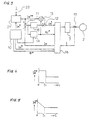
- Figure 3 is a circuit block diagram showing a second modification of the apparatus of Fig. 1.
- names, functions and applications of the AC motor 2, power converter 3, reference value generator circuit 10, adders 11 and 12, amplifier circuit 13, regulator circuit 14, multiplier 15, voltage current control circuit 15 and current detector 17 are all the same with those in the apparatus of Fig. 1, and their explanations are omitted.
- the apparatus of Fig. 3 is different from that of Fig. 1 in that the apparatus of Fig. 3 converts the reference magnetizing current value I M * output from the reference value generator circuit 10 through a current pattern generator 21 to a varying reference magnetizing current value I M **, and that an operation command switch 22 is incorporated.
- the calculation result of the adder 11 is input to the regulator circuit 14 in Fig. 3 similarly as in the apparatus of Fig.1, the amplified result of the amplifier 13, that amplifies the calculation result of the adder 11, may be input to the regulator circuit 14 in the same way as in the apparatus of Fig.2.
- the apparatus of Fig. 3 inputs a start command which indicates start point of the AC motor 2 to the current pattern generator 21 through the operation command switch 22.
- the current pattern generator 21 outputs, in response to the input start command, the varying reference magnetizing current value I M ** decreasing according to the current pattern from the initial large value to a predetermined value after a predetermined period of time has elapsed and shortens the time for the estimated resistance value to reach the true primary resistance value.
- Figure 4 is a graph showing a first example of an output variation of the current pattern generator 21 of Fig. 3.
- the abscissa represents time and the ordinate the varying reference magnetizing current value I M **, I M ** takes a large value at the zero point of time when the AC motor 2 starts and decreases to a predetermined value at T1 when a predetermined time has elapsed.
- Figure 5 is a graph showing a second example of an output variation of the current pattern generator 21 of Fig. 3.
- the abscissa represents time and the ordinate the varying reference magnetizing current value I M **.
- I M ** takes a large value at the zero point of time when the AC motor 2 starts, decreases linearly with elapse of time and reaches the predetermined value at T1 when a predetermined time has elapsed.
- Figure 6 is a graph showing a third example of an output variation of the current pattern generator 21 of Fig. 3.
- the abscissa represents time and the ordinate the varying reference magnetizing current value I M **.
- I M ** decreases exponentially with elapse of time from the initial large value at the time when the AC motor 2 starts and finally reaches the predetermined value.
- this apparatus of Fig. 3 varies the reference magnetizing current value by means of the current pattern generator to reduce the effect of induced electromotive force of the motor which affects estimation of the primary resistance value at the start of the motor, facilitates estimating the primary resistance value in a short time even if the motor is of large capacity, the secondary time constant of which is large.
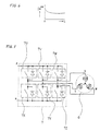
- Figure 7 is a circuit diagram showing connections between a three-phase electric power converter 7 which converts a DC current to a three-phase AC current and a three-phase AC motor 6 driven by the three-phase electric power supplied from the power converter 7.
- the three-phase electric power converter 7 is constructed by bridge-connecting six switching elements, 7U, 7V, 7W on the positive side and 7X, 7Y, 7Z on the negative side.
- a current flows through two phases of the three-phase AC motor 6 when either one of the switching elements 7U, 7V or 7W on the positive side and either one of the switching elements 7X, 7Y or 7Z on the negative side are turned on, while avoiding arm short circuit, that is, simultaneous turning-on of the switching elements which belong to the same phase.
- Figure 8 is a circuit block diagram showing a first embodiment according to the present invention.
- names, functions and applications of the reference value generator circuit 10, adders 11 and 12, amplifier circuit 13, regulator circuit 14, multiplier 15, voltage current control circuit 15 and current detector 17 are all the same with those in the apparatus of Fig. 1, and their explanations are omitted.
- the three-phase electric power converter 7 supplies three-phase AC electric power to the three-phase AC motor 6.
- Phases through which a current flows and switching elements of the power converter 7 to be turned on change with the variation of phase angle of voltage applied to the three-phase AC motor 6. Because of this, the actual primary resistance value varies with the variation of the phase angle, which may cause control accuracy deterioration.
- the first embodiment outputs a reference phase value ⁇ * which assigns a respective one of six sets or pairs of the switching elements of the power converter 7 to be simultaneously turned-on according to the assignment listed in Table 1.
- the estimated primary resistance values R 1 # s for the six pairs listed in Table 1, output from the regulator circuit 14, are stored in a phase resistance value storage circuit 31 with reference to each phase angle. Alternatively, converted estimated primary resistance values for each phase are stored in the phase resistance value storage circuit 31.
- a mean value calculation circuit 32 calculates a mean value of the stored data and the calculated mean primary resistance value R 1M # is stored in a mean resistance value storage circuit 33. The stored mean primary resistance value R 1M # is used for calculating the voltage drop across the primary resistance of the three-phase AC motor 6.
- the calculation result of the adder 11 is input to the regulator circuit 14 in Fig. 8 similarly as in the apparatus of Fig. 1, the amplified result of the amplifier 13, that amplifies the calculation result of the adder 11, may be input to the regulator circuit 14 in the same way as in the apparatus of Fig. 2.
- Figure 9 is a circuit block diagram showing a second embodiment.
- the second embodiment of Fig. 9 is constructed by providing the first embodiment of Fig. 8 with the current pattern generator circuit 21 and the operation command switch 22.
- the functions of the current pattern generator circuit 21 and the operation command switch 22 are the same with those of the apparatus of Fig. 3, and the functions of the constituents are the same with those of the first embodiment of Fig. 8. So, further explanations of the second embodiment are omitted.
- the calculation result of the adder 11 is input to the regulator circuit 14 in Fig. 9 similarly as in the apparatus of Fig. 1, the amplified result of the amplifier 13, that amplifies the calculation result of the adder 11, may be input to the regulator circuit 14 in the same way as in the apparatus of Fig. 2.
- each pair of the switching elements comprising one switching element on the positive side and another on the negative, side to be turned on at the same time to make a current flow through two phases of the three-phase AC motor.
- the primary resistance values for the six pairs are estimated and the voltage drop is obtained by using the mean value of the estimated primary resistance values.
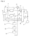
- Figure 10 is a circuit block diagram showing a third embodiment.
- names, functions and applications of the three-phase AC motor 6, three-phase electric power converter 7, reference value generator circuit 10, adders 11 and 12, amplifier circuit 13, regulator circuit 14, multiplier 15, voltage current control circuit 15 and current detector 17 are all the same with those in the first embodiment of Fig. 8, and their explanations are omitted.
- the calculation result of the adder 11 is input to the regulator circuit 14 in Fig. 10 similarly as in the apparatus of Fig. 1, the amplified result of the amplifier 13, that amplifies the calculation result of the adder 11, may be input to the regulator circuit 14 in the same way as in the apparatus of Fig. 2.
- the three-phase AC motor 6 is driven in an open phase state or an unbalance between phase currents occurs when any of the switching elements of the power converter 7 malfunctions, when the wiring between the power converter 7 and the motor 6 is broken or when the wiring is mis-connected. To solve these problems, a following test is conducted prior to driving the motor 6 to check whether the above malfunctions exist or not.
- the reference value generator circuit 10 outputs the reference phase value ⁇ * which assigns a respective one of six sets or pairs of the switching elements of the power converter 7 to be simultaneously turned on according to the assignment listed in Table 1.
- the estimated primary resistance values R 1 *s for the six pairs listed in Table 1, output from the regulator circuit 14, are stored in the phase resistance value storage circuit 31 with reference to each phase angle.
- converted estimated primary resistance values R 1 *s for each phase are stored in the phase resistance value storage circuit 31.
- a resistance value comparing circuit 41 compares the stored phase resistance values with each other and outputs deviations as the result of the comparison to a comparator 42.
- the comparator 42 outputs an alarm signal when an input deviation exceeds a predetermined value set from a deviation setter 43.
- the malfunction detection aspect of the third embodiment may advantageously be combined with any of the preceding embodiments when applied to control a multi-phase AC motor.
- the malfunction detection method estimates the primary resistance values for the six pairs and compares the estimated primary resistance values with each other to detect an intolerable unbalance between the resistance values of the phases.
- This malfunction detection method is effective for easily detecting the malfunctions in advance such as malfunctions of the switching elements, breaking of wire, open phase operation of the motor caused by breaking or mis-connection of the motor windings, and unbalance among the phase currents. Malfunctions other than the malfunctions of the switching elements, which need not consider allowable pairs of the switching elements, can be detected from at least three pairs of the switching elements.
Landscapes
- Engineering & Computer Science (AREA)
- Power Engineering (AREA)
- Control Of Ac Motors In General (AREA)
Priority Applications (1)
| Application Number | Priority Date | Filing Date | Title |
|---|---|---|---|
| EP96105889A EP0726645A2 (en) | 1993-09-17 | 1994-09-15 | Control method and apparatus for AC motor |
Applications Claiming Priority (4)
| Application Number | Priority Date | Filing Date | Title |
|---|---|---|---|
| JP230648/93 | 1993-09-17 | ||
| JP23064893 | 1993-09-17 | ||
| JP9708994 | 1994-05-11 | ||
| JP97089/94 | 1994-05-11 |
Related Child Applications (1)
| Application Number | Title | Priority Date | Filing Date |
|---|---|---|---|
| EP96105889.8 Division-Into | 1994-09-15 |
Publications (2)
| Publication Number | Publication Date |
|---|---|
| EP0644648A1 EP0644648A1 (en) | 1995-03-22 |
| EP0644648B1 true EP0644648B1 (en) | 1996-12-27 |
Family
ID=26438297
Family Applications (2)
| Application Number | Title | Priority Date | Filing Date |
|---|---|---|---|
| EP94114548A Expired - Lifetime EP0644648B1 (en) | 1993-09-17 | 1994-09-15 | Control method and apparatus and malefunction detection method and apparatus for AC motor |
| EP96105889A Withdrawn EP0726645A2 (en) | 1993-09-17 | 1994-09-15 | Control method and apparatus for AC motor |
Family Applications After (1)
| Application Number | Title | Priority Date | Filing Date |
|---|---|---|---|
| EP96105889A Withdrawn EP0726645A2 (en) | 1993-09-17 | 1994-09-15 | Control method and apparatus for AC motor |
Country Status (3)
| Country | Link |
|---|---|
| US (1) | US5623190A (show.php) |
| EP (2) | EP0644648B1 (show.php) |
| DE (1) | DE69401256T2 (show.php) |
Families Citing this family (11)
| Publication number | Priority date | Publication date | Assignee | Title |
|---|---|---|---|---|
| JPH0974794A (ja) * | 1995-09-05 | 1997-03-18 | Toyota Motor Corp | 交流電動機制御回路の異常検出装置 |
| US5880572A (en) * | 1996-04-18 | 1999-03-09 | Fuji Electric Co., Ltd. | Variable-speed control method and apparatus for AC motor |
| DE29717369U1 (de) * | 1997-09-29 | 1998-02-12 | Siemens AG, 80333 München | Digitaleingabeeinheit |
| FI112735B (fi) * | 1997-12-03 | 2003-12-31 | Kone Corp | Menetelmä synkronisen kestomagneettimoottorin ohjaamiseksi |
| JP3801471B2 (ja) * | 2001-08-31 | 2006-07-26 | 株式会社ジェイテクト | ブラシレスdcモータの電力供給線の断線検出方法、それを用いたブラシレスdcモータの制御装置、電気式動力舵取装置およびコンピュータプログラム |
| JP2004320945A (ja) * | 2003-04-18 | 2004-11-11 | Yaskawa Electric Corp | Acサーボドライバのモータ動力線断線検出方法 |
| DE102006028940B3 (de) * | 2006-06-23 | 2008-01-10 | Siemens Ag | Regler und Verfahren zur Regelung eines stufenlosen elektrischen Getriebs |
| JP4968089B2 (ja) * | 2008-01-28 | 2012-07-04 | アイシン・エィ・ダブリュ株式会社 | 電動機制御装置および駆動装置 |
| SE534522C2 (sv) * | 2008-11-13 | 2011-09-20 | Subsee Ab | Förfarande och apparat för off-line testning av flerfasiga växelströmsmaskiner |
| EP2616823B1 (en) | 2010-09-15 | 2019-10-30 | Carrier Corporation | Refrigeration system and method for determining proper wiring of multiple three-phase motors |
| WO2017152040A1 (en) | 2016-03-03 | 2017-09-08 | Eaton Corporation | Electrical motor coil short detection and protection |
Family Cites Families (12)
| Publication number | Priority date | Publication date | Assignee | Title |
|---|---|---|---|---|
| US4442393A (en) * | 1982-03-04 | 1984-04-10 | Westinghouse Electric Corp. | Apparatus and method for determining the operation of an induction motor |
| US4680526A (en) * | 1984-08-21 | 1987-07-14 | Hitachi, Ltd. | Method of controlling inverter-driven induction motor |
| FI872593A7 (fi) * | 1986-08-18 | 1988-02-19 | Siemens Ag | Foerfarande och anordning foer att driva en faeltorienterad, med en styrbar omriktare matad vridfaeltmaskin. |
| CA1284349C (en) * | 1986-08-27 | 1991-05-21 | Craig R. Conner | Flux profile control for startup of an induction motor |
| JP2585376B2 (ja) * | 1987-06-12 | 1997-02-26 | 株式会社日立製作所 | 誘導電動機の制御方法 |
| US4914386A (en) * | 1988-04-28 | 1990-04-03 | Abb Power Distribution Inc. | Method and apparatus for providing thermal protection for large motors based on accurate calculations of slip dependent rotor resistance |
| JPH02241389A (ja) * | 1989-03-14 | 1990-09-26 | Sumitomo Heavy Ind Ltd | 誘導電動機のベクトル制御装置 |
| JPH07110160B2 (ja) * | 1989-12-21 | 1995-11-22 | 三菱電機株式会社 | 誘導電動機の制御装置 |
| JP2634333B2 (ja) * | 1991-07-22 | 1997-07-23 | 三菱電機株式会社 | 誘導電動機の制御装置 |
| EP0500121B1 (en) * | 1991-02-22 | 1996-11-27 | Mitsubishi Denki Kabushiki Kaisha | Controller for induction motor |
| CA2101796C (en) * | 1992-07-21 | 1996-10-01 | Tetsuo Yamada | Vector control apparatus for induction motor |
| KR950010191B1 (ko) * | 1991-09-18 | 1995-09-11 | 삼성전자주식회사 | 유도전동기의 회전자저항 추정장치 |
-
1994
- 1994-09-15 DE DE69401256T patent/DE69401256T2/de not_active Expired - Fee Related
- 1994-09-15 EP EP94114548A patent/EP0644648B1/en not_active Expired - Lifetime
- 1994-09-15 EP EP96105889A patent/EP0726645A2/en not_active Withdrawn
- 1994-09-16 US US08/307,895 patent/US5623190A/en not_active Expired - Fee Related
Also Published As
| Publication number | Publication date |
|---|---|
| US5623190A (en) | 1997-04-22 |
| EP0644648A1 (en) | 1995-03-22 |
| DE69401256T2 (de) | 1997-05-28 |
| EP0726645A2 (en) | 1996-08-14 |
| EP0726645A3 (show.php) | 1996-08-28 |
| DE69401256D1 (de) | 1997-02-06 |
Similar Documents
| Publication | Publication Date | Title |
|---|---|---|
| US7039542B2 (en) | Method of measuring motor constant for induction motor | |
| US5594670A (en) | Apparatus for measuring circuit constant of induction motor with vector control system and method therefor | |
| EP0233948B1 (en) | Method of controlling a three-phase induction motor | |
| EP0644648B1 (en) | Control method and apparatus and malefunction detection method and apparatus for AC motor | |
| JPWO2017122309A1 (ja) | 電動機制御装置 | |
| US20190162773A1 (en) | Motor driving device and measuring method | |
| JPH0775399A (ja) | 可変速装置 | |
| US9397554B2 (en) | Motor drive device having function of estimating dead time in output stage | |
| US6452360B1 (en) | Auto tuning and parameter identification of a control circuit | |
| JP3019653B2 (ja) | 交流電動機の制御装置及び交流電動機の定数測定方法 | |
| JP3141688B2 (ja) | 交流電動機の制御方法と異常検出方法 | |
| JP3092839B2 (ja) | 定数測定設定機能付きインバータ装置 | |
| JP5333411B2 (ja) | 誘導電動機のベクトル制御装置 | |
| JP2850096B2 (ja) | 定数測定設定機能付きインバータ制御方法 | |
| JP3638030B2 (ja) | 定数測定設定機能付きインバ−タの制御方法 | |
| JP2000095453A (ja) | エレベータの制御装置 | |
| JP2716920B2 (ja) | Pwmインバータ装置 | |
| US20250150015A1 (en) | Method for monitoring an electrical machine, inverter arrangement and drive system | |
| JP3329672B2 (ja) | 誘導電動機定数測定装置 | |
| JP2730017B2 (ja) | インバータ装置 | |
| JP7644073B2 (ja) | 誘導電動機駆動装置 | |
| JP2665125B2 (ja) | インバータ装置 | |
| JP3849857B2 (ja) | 交流電動機の抵抗測定方法 | |
| JP3302799B2 (ja) | インバータ装置 | |
| Sayed-Ahmed et al. | Diagnosis of inter-turn short circuit for a polyphase induction motor in closed-loop vector-controlled drives |
Legal Events
| Date | Code | Title | Description |
|---|---|---|---|
| PUAI | Public reference made under article 153(3) epc to a published international application that has entered the european phase |
Free format text: ORIGINAL CODE: 0009012 |
|
| AK | Designated contracting states |
Kind code of ref document: A1 Designated state(s): DE GB IT |
|
| 17P | Request for examination filed |
Effective date: 19950621 |
|
| 17Q | First examination report despatched |
Effective date: 19950719 |
|
| GRAG | Despatch of communication of intention to grant |
Free format text: ORIGINAL CODE: EPIDOS AGRA |
|
| GRAH | Despatch of communication of intention to grant a patent |
Free format text: ORIGINAL CODE: EPIDOS IGRA |
|
| GRAH | Despatch of communication of intention to grant a patent |
Free format text: ORIGINAL CODE: EPIDOS IGRA |
|
| GRAA | (expected) grant |
Free format text: ORIGINAL CODE: 0009210 |
|
| AK | Designated contracting states |
Kind code of ref document: B1 Designated state(s): DE GB IT |
|
| XX | Miscellaneous (additional remarks) |
Free format text: TEILANMELDUNG 96105889.8 EINGEREICHT AM 15/04/96. |
|
| ITF | It: translation for a ep patent filed | ||
| REF | Corresponds to: |
Ref document number: 69401256 Country of ref document: DE Date of ref document: 19970206 |
|
| PLBE | No opposition filed within time limit |
Free format text: ORIGINAL CODE: 0009261 |
|
| STAA | Information on the status of an ep patent application or granted ep patent |
Free format text: STATUS: NO OPPOSITION FILED WITHIN TIME LIMIT |
|
| 26N | No opposition filed | ||
| REG | Reference to a national code |
Ref country code: GB Ref legal event code: IF02 |
|
| REG | Reference to a national code |
Ref country code: GB Ref legal event code: 746 Effective date: 20020620 |
|
| PGFP | Annual fee paid to national office [announced via postgrant information from national office to epo] |
Ref country code: GB Payment date: 20030910 Year of fee payment: 10 |
|
| PGFP | Annual fee paid to national office [announced via postgrant information from national office to epo] |
Ref country code: DE Payment date: 20030925 Year of fee payment: 10 |
|
| PG25 | Lapsed in a contracting state [announced via postgrant information from national office to epo] |
Ref country code: GB Free format text: LAPSE BECAUSE OF NON-PAYMENT OF DUE FEES Effective date: 20040915 |
|
| PG25 | Lapsed in a contracting state [announced via postgrant information from national office to epo] |
Ref country code: DE Free format text: LAPSE BECAUSE OF NON-PAYMENT OF DUE FEES Effective date: 20050401 |
|
| GBPC | Gb: european patent ceased through non-payment of renewal fee |
Effective date: 20040915 |
|
| PG25 | Lapsed in a contracting state [announced via postgrant information from national office to epo] |
Ref country code: IT Free format text: LAPSE BECAUSE OF NON-PAYMENT OF DUE FEES;WARNING: LAPSES OF ITALIAN PATENTS WITH EFFECTIVE DATE BEFORE 2007 MAY HAVE OCCURRED AT ANY TIME BEFORE 2007. THE CORRECT EFFECTIVE DATE MAY BE DIFFERENT FROM THE ONE RECORDED. Effective date: 20050915 |