EP0644115B1 - Schleppfahrzeug für Flugzeuge mit oder ohne angehobenem Bugrad - Google Patents
Schleppfahrzeug für Flugzeuge mit oder ohne angehobenem Bugrad Download PDFInfo
- Publication number
- EP0644115B1 EP0644115B1 EP94113662A EP94113662A EP0644115B1 EP 0644115 B1 EP0644115 B1 EP 0644115B1 EP 94113662 A EP94113662 A EP 94113662A EP 94113662 A EP94113662 A EP 94113662A EP 0644115 B1 EP0644115 B1 EP 0644115B1
- Authority
- EP
- European Patent Office
- Prior art keywords
- tractor
- wheels
- aircraft
- rollers
- idle
- Prior art date
- Legal status (The legal status is an assumption and is not a legal conclusion. Google has not performed a legal analysis and makes no representation as to the accuracy of the status listed.)
- Expired - Lifetime
Links
Images




Classifications
-
- B—PERFORMING OPERATIONS; TRANSPORTING
- B64—AIRCRAFT; AVIATION; COSMONAUTICS
- B64F—GROUND OR AIRCRAFT-CARRIER-DECK INSTALLATIONS SPECIALLY ADAPTED FOR USE IN CONNECTION WITH AIRCRAFT; DESIGNING, MANUFACTURING, ASSEMBLING, CLEANING, MAINTAINING OR REPAIRING AIRCRAFT, NOT OTHERWISE PROVIDED FOR; HANDLING, TRANSPORTING, TESTING OR INSPECTING AIRCRAFT COMPONENTS, NOT OTHERWISE PROVIDED FOR
- B64F1/00—Ground or aircraft-carrier-deck installations
- B64F1/22—Ground or aircraft-carrier-deck installations for handling aircraft
- B64F1/223—Ground or aircraft-carrier-deck installations for handling aircraft for towing aircraft
- B64F1/225—Vehicles specially adapted therefor, e.g. aircraft tow tractors
- B64F1/227—Vehicles specially adapted therefor, e.g. aircraft tow tractors for direct connection to aircraft, e.g. tow tractors without towing bars
-
- B—PERFORMING OPERATIONS; TRANSPORTING
- B64—AIRCRAFT; AVIATION; COSMONAUTICS
- B64F—GROUND OR AIRCRAFT-CARRIER-DECK INSTALLATIONS SPECIALLY ADAPTED FOR USE IN CONNECTION WITH AIRCRAFT; DESIGNING, MANUFACTURING, ASSEMBLING, CLEANING, MAINTAINING OR REPAIRING AIRCRAFT, NOT OTHERWISE PROVIDED FOR; HANDLING, TRANSPORTING, TESTING OR INSPECTING AIRCRAFT COMPONENTS, NOT OTHERWISE PROVIDED FOR
- B64F1/00—Ground or aircraft-carrier-deck installations
- B64F1/22—Ground or aircraft-carrier-deck installations for handling aircraft
-
- Y—GENERAL TAGGING OF NEW TECHNOLOGICAL DEVELOPMENTS; GENERAL TAGGING OF CROSS-SECTIONAL TECHNOLOGIES SPANNING OVER SEVERAL SECTIONS OF THE IPC; TECHNICAL SUBJECTS COVERED BY FORMER USPC CROSS-REFERENCE ART COLLECTIONS [XRACs] AND DIGESTS
- Y10—TECHNICAL SUBJECTS COVERED BY FORMER USPC
- Y10S—TECHNICAL SUBJECTS COVERED BY FORMER USPC CROSS-REFERENCE ART COLLECTIONS [XRACs] AND DIGESTS
- Y10S180/00—Motor vehicles
- Y10S180/904—Traction dollies for aircraft
Definitions
- This invention covers a tractor without drawbars for towing aircraft through its front steering wheels, which may be lifted or not.
- Several types of vehicles are known to tow airplanes, but they all have some drawbacks and defects.
- US-A-2987133 illustrates a towing vehicle provided with a long rotating framework, the free end of which is fitted with two wheels driven by the framework and a system connecting the wheels of the aircraft to the shaft.
- the wheels rotating in touch with the aircraft cause the latter to move.
- US-A-3005510 is also known, which features a motor-driven belt to be inserted between the wheel sets of the aircraft.
- EP-A-0156842 is known, grouping two original Finnish Patents FI-A-75310 and FI-A-78426.
- This document describes a trolley with a recessed central zone in which the lateral non steering wheel or wheels of the airplane may penetrate.
- This trolley is provided with mobile rollers, moving in transverse vertical as well as in horizontal lengthwise direction, so that they may be placed adjacent, in front of or behind the wheels of the aircraft. At least one of these rollers is motor-driven and will drive the non-steering wheels or set of lateral wheels of the plane.
- the above described towing device is applied to the lateral non-steering wheels of the airplane, so that the pilot has to steer the plane during towing or other persons shall move the front steering wheels of the aircraft with the aid of proper equipment.
- front and rear rolllers are controlled by one single mechanism that will approach and grip the wheels of the airplane so that the docking manoeuvre takes much time and is difficult.
- the tractor is essentially provided with two motor-driven front rollers mounted on a transverse mobile axle, lengthwise to the tractor, while two more motor-driven rollers at the rear are revolving around a vertical axis from a central to a lateral position and vice-versa.
- the steering front wheels of the aircraft are gripped between these roller sets which, being motor-driven, will cause the aircraft wheels to rotate thus towing the aircraft without direct intervention of the tractor, the driving system of which is cut-out during towing.
- GB-A-795323 discloses a carrier provided with lifting mechanism to raise an aircraft off the ground and so to hold the aircraft during transportation along the ground surface.
- an aircraft ground handling vehicle is provided of support platform movably mounted on the chassis and of means for loading the nose-wheels of the aircraft onto these platform.
- WO-A-9014269 relates to a wheel gripping transfer device, which includes two rollers, placed and pressed on opposite sides of the wheels of an aircraft, at last one of these rollers is a friction roller driven by a motor.
- EP-A-0 309 760 discloses in an other solution a device for gripping and lifting the wheels of an aircraft.
- This invention has the aim to provide a tractor for towing aircraft through its two front steering wheels, without using drawbars and without motor-driven rollers.
- the tractor subject matter of this invention consists of a rear driver's cab, four wheels, two of which are motor-driven and two are steering wheels; a recess is provided in the front part of the platform (steerage being reversed with respect to normal steering, so that the tractor can more easily approach the wheels of the airplane), an idle roller having its axis transverse to the tractor, is placed in this recess and is supported by levers controlled by hydraulic fluid powered pistons thus moving the idle roller back and forth.
- Two idle front rollers are located in the front part of the recess and are mounted on their axes, each end of which is connected to a sliding device causing the front rollers to approach the rear roller and vice-versa as well as the rotation of these front rollers during their opening phase to permit the aircraft wheels to enter and leave the tractor recess.
- the tractor has an apron that may be lowered to receive and unload the front steering wheels of the airplane and is lifted during towing.
- This apron is rigidly connected to the tractor frame; hydraulic fluid powered pistons and a leverage system will jack up the apron and framework with respect to the tractor wheels.
- the tractor similar to the first solution, is however without apron so that the front steering wheels of the aircraft remain on the ground.
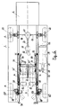
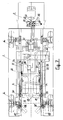
- Figures 1 thru 9 show the solution for a tractor with apron on which to lift the front steering wheels of the aircraft.
- 1 indicates the tractor with selfbearing framework, the driver's cab 2 being located at the rear, while a recess 3 in the front part will receive the front steering wheels 4 of the aircraft 5 and the related docking system.
- the driver's cab 2 is provided with a control system for moving back and forth in direction of the arrow F in fig.1 so that it will be possible to adjust the distance between the cab 2 and the airplane having its nose 5 positioned above the cab 2 during towing.
- the tractor has four tyre mounted wheels 6, two of which are driving wheels.
- Each wheel 6 (cf.Fig.9) is supported by one end of knuckle arms and in particular by an upper 9 and by a lower knuckle arm 10, the other end of these knuckle arms being secured to the chassis or framework of the tractor 1.
- the upper arm 9 is suspended and controlled by a hydraulic cylinder 7 lifting and lowering the tractor frame and a nitrogen bell 8.
- a microswitch 11 acts as a limit switch for suspension movements so that it will be possible to take advantage of the whole capacity of the hydraulic cylinder 7 to jack up the tractor framework 1 on which the aircraft is resting, as will be described hereinafter and to ensure, with the aid of the bell 8, comfortable driving conditions for the tractor including traversing movements caused by the wheels 4 of the aircraft 5.
- the operation mode of the assembly will be explained in the following pages.
- the front wheel set 6 (fig.5) are steering by means of a servo-assisted hydraulic mechanism that will let the front part of the recess free.
- This mechanism will have for each wheel 6, a control arm 12, a control rod 13 for the arm 12, an intermediate lever control and steering adjustment, a knuckle 15 connecting the lever 14 to the double acting cylinder 16 controlling both wheels 6.
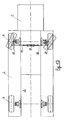
- the rear wheels 6 are not steering, but they might be as shown in fig. 13.
- the tractor is driven by a heat engine and by a hydromotor or by a hydrodynamic gear with reduction and differential unit.
- the tractor may also have an electric motor with storage battery.
- the engine or motor is mounted sideways so as to offer the driver ample view and maximum safety during docking and manoeuvring of the aircraft.
- the main characteristic of the tractor subject matter of this invention is its system for docking and knockoff of the front steering wheels 4 of the aircraft, in sequence associated with the wheel lifting device by means of the suspension cylinders 7 of the tractor 1.
- FIG. 6 and 8 This docking and knockoff of the front steering wheels 4 of the airplane is shown in Fig. 6 and 8.
- the tractor 1 has a recess 3 in its front part in which the wheels 4 of the front undercarriage may be lodged.
- the recess 3 has also an apron 32 connected to the framework of the tractor 1 on which the wheels 4 of the plane will mount to be lifted.
- This docking and knockoff system has also two frontal and sideways positioned idle rollers 28, connected by their shaft to lateral sliders 30 moving in guides 29; the front end of these guides has a cam shaped outwards bent deflection 29A.
- These sliders 30 are moving in the guides 29, 29A by means of hydraulic fluid powered pistons 31.
- the rollers 28 When the sliders are running in the straight longitudinal section 29, the rollers 28 are inwards directed, but when the sliders 20' enter the cam section 29A of the guide, they take a 90° turn to occupy the position 28'.
- the external rollers will permit the entrance and exit of the aircraft wheels 4, whereas in central position 28, they will push against these wheels when entering the recess 3, pushing them on the apron 32. where they are blocked during towing.
- the rear device for docking and knockoff of the aircraft wheels 4 after towing consists of an idle roller 36 having its axis transverse to the tractor, supported at both ends by two lateral levers 35 hinged on fixed pivots. Two lateral hydraulic fluid powered pistons 34 cause the levers 35 to rotate while moving the idle roller 36, 36' backwards and forewards. It is clear that the aircraft wheels 4, when entering the recess 3 of the tractor 1, will rest against the idle roller 36' and will be pushed on the apron 32 by the front rollers 28, thus moving the rear roller into its position 36. The wheels 4 of the aircraft will thus remain imprisoned between the rollers 28, 36 while resting on the apron which will then be lifted for towing. After towing and after the front rollers 28 have been opened, the controlled pressure cylinders are actuated, pushing the idle rear roller 16 foreward, which in turn knocks off the wheels 4 from the apron 32.
- the wheels 4 of the aircraft are blocked on the apron by microswitches 37 triggered by the levers 35 of the supporting and knockoff roller 36.
- the apron 32 has a central wedge shaped guide step 33 to guide the aircraft wheels 4.
- the apron is rigidly connected to the tractor framework 1 so that, when actuating the hydraulic cylinders 7 of the suspensions, the whole tractor framework 1 is jacked up, including the apron 32, which in turn lifts the wheels 4 of the airplane. This means that the wheels 4 of the plane are not resting on the ground during towing and that the tractor-aircraft assembly is steered only from the driver's cab.
- the control system of the tractor 1 further includes the following, as illustrated in fig.7:
- a second solution is very much similar to the first one described above except for the fact that there is no apron 32 on which the wheels 4 of the aircraft are lifted.
- the wheels 4 are equally blocked by the rear roller 36 and by the front rollers 28, but they remain on the ground; during towing, the aircraft wheels are rolling on the ground causing the rollers to rotate since the apron 32 and the related wedge shaped guide step 13 are lacking ; the front 28 and rear rollers 36 are provided with ring shaped blocking and guiding devices 46 as shown in fig. 10, 11 and 12.
- Fig. 10 shows the position of the front 28 and rear rollers 36 when in touch with the wheels 4, 4' having different diameters and belonging to medium-large sized aircraft (AERBUS) or medium-small airplanes (DC9) categories.
- AERBUS medium-large sized aircraft
- DC9 medium-small airplanes
- two rollers 47, 48 are mounted instead of one single rear roller 36 since they better adjust to the various diameters of the aircraft wheels 4, 4' and may be used to position the different sized wheels 4, 4' with their axle on a transverse plane X - X with respect to the tractor 1, also including the front wheel axles 6 of the tractor.
- These rollers 47, 48 are supported at both ends by two levers 52 actuated by hydraulic fluid powered cylinders 53.
- Fig. 12 shows another variation in which the idle rear roller 36 is fixed mounted without shifting and knockoff cylinders 34.
- This solution may be adopted in a tractor without apron, since the tractor may move away from the aircraft simply by backing.
- the idle roller 36 is usually consisting of two components mounted on the same bearing shaft transverse to the tractor to permit independent rotation of the aircraft and of the tractor wheels in curves.
- Fig. 13 shows the steering system of the rear wheels as adopted for tractor 1 without apron 32.
- This servo-assisted hydraulic steering system consists of an arm 49 controlling the wheels 6, a control rod 50 for the arm 49 and a double acting cylinder 51 actuating the rods 50.
- fig. 6 shows an example of guide rolls 54 to facilitate penetration of the front steering wheels 4 of the aircraft in the tractor recess 3.
Landscapes
- Engineering & Computer Science (AREA)
- Mechanical Engineering (AREA)
- Aviation & Aerospace Engineering (AREA)
- Body Structure For Vehicles (AREA)
- Guiding Agricultural Machines (AREA)
- Automatic Cycles, And Cycles In General (AREA)
- Vehicle Body Suspensions (AREA)
- Power Steering Mechanism (AREA)
- Steering-Linkage Mechanisms And Four-Wheel Steering (AREA)
Claims (16)
- Schleppfahrzeug zum Schleppen von Flugzeugen mit Hilfe der zwei Bugräder, wobei das Schleppfahrzeug (1) mit vier bereiften Rädern (6) ausgestattet ist, die in vorderen und hinteren Gruppen auf unabhängigen Achsen quer zum Schleppfahrzeug befestigt sind, wobei die einen die Lenkräder und die anderen die Antriebsräder sind; mit einer Fahrerkabine (2), die sich im hinteren Abschnitt befindet, und einer Aussparung, in der die Räder des Flugzeuges untergebracht werden, im vorderen Abschnitt des Schleppfahrzeuges; mit zwei seitlichen, vorderen Leerlaufwalzen (28) zum Ergreifen der Räder des Flugzeuges; zwei Schiebern (30), die an den Wellen der vorderen Leerlaufwalzen befestigt sind; zwei seitlichen Führungen (29), in denen sich die Schieber bewegen; zwei seitlichen, mit Hydraulikflüssigkeit angetriebenen Zylindern (31), welche die Schieber der vorderen Leerlaufwalzen betätigen; einer hinteren Leerlaufwalze (36), deren Achse quer zum Schleppfahrzeug liegt und als Stütze für die Flugzeugräder und zum Entfernen derselben vom Schleppfahrzeug dient; und einem Steuergerät am Schleppfahrzeug oder in der Fahrerkabine, dadurch gekennzeichnet, dass:- sich die Fahrerkabine im hinteren Abschnitt befindet, so dass sie zu den Bugrädern (4) des Flugzeuges (5) und zur Aussparung (3) hin gerichtet ist;- jedes Rad (6) des Schleppfahrzeuges (1) von einem oberen (9) und einem unteren Gelenksarm (10) gestützt wird, die am Rad (6) und am Rahmen (1) des Schleppfahrzeuges befestigt sind,- jeder obere Gelenksarm (9) von einem hydraulischen Zylinder (7) und einer Stickstoffglocke (8) gesteuert wird, um den Schleppfahrzeugrahmen (1) zu stützen und hochzuheben,- ein Mikroschalter (11) den Hebepfad des Schleppfahrzeugrahmens (1) durch den Zylinder (7) begrenzt,- eine Schürze (32) in der vorderen Aussparung (3) vorhanden ist, welche am Schleppfahrzeugrahmen (1) befestigt ist und daher gemeinsam mit diesem Rahmen angehoben und abgesenkt wird, um die Räder (4) des Flugzeugs aufzunehmen,- das vordere Ende der zwei seitlichen Führungen (29) eine nockenförmige, nach aussen gebogene Ablenkung (29A) aufweist, so dass die vorderen Leerlaufwalzen (28) nach innen gerichtet sind, wenn die Schieber im geraden, länglichen Abschnitt der Führungen (29) verlaufen, während sie eine 90°-Wende nach aussen vollführen, wenn die vorderen Leerlaufwalzen (28') in den Nockenabschnitt (29A) der Führung am Eingang der Aussparung (3) eindringen,- zwei seitliche Hebel (35) vorhanden sind, von denen jeweils ein Ende mit einem Gelenksarm der hinteren Leerlaufwalze (36) verbunden ist, und das andere Ende mittels einer gelenkigen Verbindung mit dem Schleppfahrzeugrahmen (1) verbunden ist;- zwei durch Hydraulikflüssigkeit betätigte Zylinder (34) auf die Hebel (35) wirken, um die hintere Leerlaufwalze (36) nach hinten oder nach vorne zu drücken,- ein Mikroschalter (37) die Blockierung der Räder (4) des Flugzeuges gegen die hintere Walze (36) auslöst, so dass die Flugzeugräder (4) in die Aussparung des Schleppfahrzeuges (1) hineingegeben, auf die Schürze (32) gestellt, durch die vorderen (28) und die hintere Leerlaufwalze (36) blockiert, vom Boden hochgehoben und nach dem Schleppen auf den Boden abgesenkt werden können.
- Schleppvorrichtung nach Anspruch 1, dadurch gekennzeichnet, dass er mit einem Mechanismus zum Bewegen der Fahrerkabine (2) nach vorne oder nach hinten ausgestattet ist, um zu verhindern, dass diese mit dem Flugzeug (5) in Berührung kommt.
- Schleppvorrichtung nach Anspruch 1, dadurch gekennzeichnet, dass die Schürze (32) eine keilförmige Führungsstufe für die Räder (4) des Flugzeuges aufweist.
- Schleppvorrichtung nach Anspruch 1, dadurch gekennzeichnet, dass das Steuergerät enthält:- einen Hydraulikverteiler (38),- eine Steuerdrucktaste (39) für die Zylinder (31), welche die Schliessung der vorderen Leerlaufwalzen (28) betätigen;- eine Steuerdrucktaste (40) zum Öffnen der Walzen (28);- ein Proportionalventil (41) für die verschiedenen Dienste der Radaufhängungen (6);- ein Druckentlastungsventil (42) für die Abwurfkolben (34);- eine Drucktaste (43) zum Betätigen der Zylinder (7) der Radaufhängungen (6) während des Hochhebens;- einen Hebel (44) zum Antrieb des Schleppfahrzeugs (1);- eine Drucktaste (45) zur Betätigung der Aufhängungszylinder (7) während des Absenkens.
- Betrieb des Schleppfahrzeuges nach Anspruch 4, dadurch gekennzeichnet, dass das Ankuppeln und Schleppen des Flugzeuges durch das Schleppfahrzeug mit den folgenden Schritten ausgeführt wird:- der Bediener bewegt das Schleppfahrzeug in Richtung der Bugräder des Flugzeuges und bewegt das Schleppfahrzeug vorwärts, bis die Räder des Flugzeuges in die Aussparung (3) eindringen und gegen die Walze (36) drücken, welche in ihre Stellung (36') gebracht ist,- danach senkt er das Schleppfahrzeug durch Betätigung der Drucktaste (45), welche die Aufhängungszylinder während des Absenkens betätigt, und erst nachdem das Schleppfahrzeug abgesenkt wurde, drückt er auf die Drucktaste (39), um die Zylinder (31) zu betätigen, welche die Antriebswalzen (28) mit den Rädern (4) des Flugzeuges in Kontakt bringen und diese Räder (4) auf die Schürze (32) drücken,- das Proportionalventil (41) stoppt die Räder in der richtigen Stellung,- das Druckentlastungsventil (42) ermöglicht die Einstellung des Druckes der beiden Zylinder (34) auf den erforderlichen Wert, bis die Räder (4) des Flugzeuges mit der Walze (36) und die Walzen (28) in Berührung kommen,- nachdem das Flugzeug auf das Schleppfahrzeug geladen wurde, drückt der Bediener auf die Drucktaste (43), welche die Zylinder (7) der Aufhängungen betätigt, die das Schleppfahrzeug hochheben; die Strecke des Hochhebens wird von den Mikroschaltern (11) geregelt, welche die Bewegungen der Aufhängung begrenzen,- nach Beendigung dieser Schritte wird der Steuerungshebel (44) verwendet, um das Flugzeug durch Ziehen oder Schieben nach vorne oder nach hinten zu bewegen;- gemäss des auszuführenden Betriebes beschleunigt der Fahrer den Verbrennungsmotor, bis die erforderliche Geschwindigkeit erreicht wird.
- Betrieb des Schleppfahrzeuges wie in Anspruch 4 beschrieben, dadurch gekennzeichnet, dass das Flugzeug vom Schleppfahrzeug durch die folgenden Schritte entladen wird:- der Bediener drückt zuerst auf die Drucktaste (45), welche die Zylinder der Aufhängungen (7) betätigt, um die Schürze (32) und das Flugzeug auf Bodenebene abzusenken,- danach drückt er auf die Drucktaste (40), welche die Zylinder (31) betätigt, um die Räder (4) des Flugzeuges von den Greifwalzen (28) zu entlassen, bis die letztern ihre Ruhestellung (28') erreichen,- das Flugzeug wird danach automatisch von der Schürze (32) durch die beiden Zylinder (34) entladen,- nach dem Entladen drückt der Bediener auf die Drucktaste (45), um das Schleppfahrzeug hochzuheben, und er verwendet danach den Ganghebel und das Gaspedal, um das Schleppfahrzeug mit der gewünschten Geschwindigkeit zu fahren.
- Schleppfahrzeug zum Schleppen von Flugzeugen mit Hilfe der zwei Bugräder, wobei das Schleppfahrzeug (1) mit vier bereiften Rädern (6) ausgestattet ist, die in vorderen und hinteren Gruppen auf unabhängigen Achsen quer zum Schleppfahrzeug befestigt sind, wobei die einen die Lenkräder und die anderen die Antriebsräder sind; mit einer Fahrerkabine (2), die sich im hinteren Abschnitt befindet, und einer Aussparung, in der die Räder des Flugzeuges untergebracht werden, im vorderen Abschnitt des Schleppfahrzeuges; mit zwei seitlichen, vorderen Leerlaufwalzen (28) zum Ergreifen der Räder des Flugzeuges; zwei Schiebern (30), die an den Wellen der vorderen Leerlaufwalzen befestigt sind; zwei seitlichen Führungen (29), in denen sich die Schieber bewegen; zwei seitlichen, mit Hydraulikflüssigkeit angetriebenen Zylindern (31), welche die Schieber der vorderen Leerlaufwalzen betätigen; einer hinteren Leerlaufwalze (36), deren Achse quer zum Schleppfahrzeug liegt und als Stütze für die Flugzeugräder und zum Entfernen derselben vom Schleppfahrzeug dient; und einem Steuergerät am Schleppfahrzeug oder in der Fahrerkabine, dadurch gekennzeichnet, dass:- sich die Fahrerkabine im hinteren Abschnitt befindet, so dass sie zu den Bugrädern (4) des Flugzeuges (5) und zur Aussparung (3) hin gerichtet ist;- zwei seitliche vordere Leerlaufwalzen (28) zum Ergreifen der Räder des Flugzeuges vorhanden sind;- das vordere Ende der zwei seitlichen Führungen (29) eine nockenförmige, nach aussen gebogene Ablenkung (29A) aufweist, so dass die Walzen (28) nach innen gerichtet sind, wenn die Schieber im geraden, länglichen Abschnitt der Führungen (29) verlaufen, währen sie eine 90°-Wende nach aussen vollführen, wenn die Walzen (28') in den Nockenabschnitt (29A) der Führung am Eingang der Aussparung (3) eindringen, so dass die Flugzeugräder (4) in die Aussparung des Schleppfahrzeuges (1) hineingegeben und von den vorderen (28) und hinteren Leerlaufwalzen (36) blockiert werden können, so dass die Räder (4) des Flugzeuges während des Schleppvorganges am Boden rollen.
- Schleppfahrzeug nach Anspruch 7, dadurch gekennzeichnet, dass die vorderen (23) und hinteren Walzen (36) mit Ringen (46) versehen sind, welche die Räder (4) des Flugzeuges ergreifen und führen.
- Schleppfahrzeug nach Anspruch 7, dadurch gekennzeichnet, dass die hintere Walze (36) in zwei Komponenten an derselben Tragewelle quer zum Schleppfahrzeug (1) befestigt ist, so dass es für die Flugzeug-Schleppfahrzeug-Gruppe einfacher ist, Kurven zu machen.
- Schleppfahrzeug nach Anspruch 1 und 7, dadurch gekennzeichnet, dass die hintere Leerlaufwalze durch zwei Leerlaufwalzen (46, 47) ersetzt werden kann, welche sich am Ende der Hebel (52) befinden, die von den durch Hydraulikflüssigkeit angetriebenen Zylindern (53) gesteuert werden, um diese Walzen (46, 47) besser an die verschiedenen Raddurchmesser (4, 4') des zu schleppenden Flugzeuges anzupassen, und damit die Radachsen (4, 4') immer an derselben Querebene (X-X) gehalten werden können wie die Achsen der Vorderräder (6) des Schleppfahrzeuges (1).
- Schleppfahrzeug nach Anspruch 7, dadurch gekennzeichnet, dass die hintere Walze (36, 46, 47) am Schleppfahrzeugrahmen (1) befestigt ist.
- Schleppfahrzeug nach Anspruch 1, dadurch gekennzeichnet, dass es von einem Verbrennungsmotor (18) oder einem Hydromotor oder Elektromotor angetrieben wird.
- Schleppfahrzeug nach Anspruch 1, dadurch gekennzeichnet, dass der Motor seitlich befestigt ist, um dem Fahrer klare Sicht zu ermöglichen.
- Schleppfahrzeug nach Anspruch 1, dadurch gekennzeichnet, dass die Lenkung über die Vorderräder und/oder die Hinterräder erfolgen kann.
- Schleppfahrzeug nach Anspruch 13, dadurch gekennzeichnet, dass das Lenkgetriebe der Vorderräder über Stangen (13) und Steuerhebel (14) verfügt, die sich rund um die vordere Aussparung (3) des Schleppfahrzeuges (1) erstrecken.
- Schleppfahrzeug nach Anspruch 1, dadurch gekennzeichnet, dass Führungswalzen (54) vorhanden sind, um die Bugräder (4) des Flugzeuges in die Aussparung (3) des Schleppfahrzeuges (1) zu führen.
Applications Claiming Priority (2)
| Application Number | Priority Date | Filing Date | Title |
|---|---|---|---|
| ITGE930082A IT1263472B (it) | 1993-09-20 | 1993-09-20 | Trattore per il traino di aeromobile attraverso le sue ruote centrali anteriori sterzanti,con sollevamento o meno delle stesse. |
| ITGE930082 | 1993-09-20 |
Publications (2)
| Publication Number | Publication Date |
|---|---|
| EP0644115A1 EP0644115A1 (de) | 1995-03-22 |
| EP0644115B1 true EP0644115B1 (de) | 1997-04-09 |
Family
ID=11354465
Family Applications (1)
| Application Number | Title | Priority Date | Filing Date |
|---|---|---|---|
| EP94113662A Expired - Lifetime EP0644115B1 (de) | 1993-09-20 | 1994-09-01 | Schleppfahrzeug für Flugzeuge mit oder ohne angehobenem Bugrad |
Country Status (8)
| Country | Link |
|---|---|
| US (1) | US5549436A (de) |
| EP (1) | EP0644115B1 (de) |
| AT (1) | ATE151366T1 (de) |
| DE (1) | DE69402492T2 (de) |
| DK (1) | DK0644115T3 (de) |
| ES (1) | ES2102110T3 (de) |
| GR (1) | GR3023889T3 (de) |
| IT (1) | IT1263472B (de) |
Families Citing this family (33)
| Publication number | Priority date | Publication date | Assignee | Title |
|---|---|---|---|---|
| DE4447860C2 (de) * | 1994-05-02 | 2002-03-28 | Goldhofer Fahrzeugwerk | Schleppfahrzeug zum Manövrieren von Flugzeugen |
| DE19721315C1 (de) | 1997-05-21 | 1998-06-10 | Krauss Maffei Verkehrstechnik | Schleppfahrzeug für Flugzeuge |
| AUPQ463099A0 (en) * | 1999-12-14 | 2000-01-13 | Nepean Engineering Pty Ltd | Tug for aircraft |
| GB0217028D0 (en) * | 2002-07-23 | 2002-08-28 | Douglas Equipment Ltd | An aircraft handler |
| CA2480376C (en) * | 2003-09-04 | 2013-04-09 | Justoy Pty Ltd | Article handling apparatus |
| US8544792B2 (en) * | 2006-09-28 | 2013-10-01 | Israel Aerospace Industries Ltd. | Towbarless airplane tug |
| US9403604B2 (en) | 2006-09-28 | 2016-08-02 | Israel Aerospace Industries Ltd. | System and method for transferring airplanes |
| US7975959B2 (en) * | 2006-09-28 | 2011-07-12 | Israel Aerospace Industries Ltd. | System and method for transferring airplanes |
| US8245980B2 (en) * | 2006-09-28 | 2012-08-21 | Israel Aerospace Industries Ltd. | System and method for transferring airplanes |
| US8636461B2 (en) | 2006-10-13 | 2014-01-28 | Carl L. Hammonds | Omni-directional aircraft transporter with hinged gate for moving aircraft |
| US8967939B2 (en) | 2006-10-13 | 2015-03-03 | Hammonds Technical Services, Inc. | Aircraft transporter dolly with hinged gate for moving aircraft |
| ATE516155T1 (de) * | 2006-10-13 | 2011-07-15 | Hammonds Technical Serv Inc | Omnidirektionaler schleppstangenloser flugzeugtransporter und flugzeugtransportverfahren |
| US9199745B2 (en) * | 2007-05-16 | 2015-12-01 | Israel Aerospace Industries Ltd. | System and method for transferring airplanes |
| FR2937777B1 (fr) * | 2008-10-23 | 2010-12-17 | Airbus Sas | Procede pour faire rouler un aeronef au sol |
| IL198950A (en) | 2008-11-25 | 2013-01-31 | Israel Aerospace Ind Ltd | Towbarless airplane tug |
| US7976029B2 (en) * | 2009-04-29 | 2011-07-12 | Richard T. Plummer | Airplane trailer |
| US20110073706A1 (en) * | 2009-09-29 | 2011-03-31 | Shin Katsumata | Aircraft tug |
| US8181725B2 (en) * | 2009-09-29 | 2012-05-22 | Hamilton Sundstrand Corporation | Aircraft tug |
| IL250593A (en) | 2010-02-16 | 2017-07-31 | Israel Aerospace Ind Ltd | A method of towing a plane by towing aircraft |
| IL206061A0 (en) | 2010-05-30 | 2010-11-30 | Israel Aerospace Ind Ltd | Controller for a hydraulic drive system |
| IL206262A0 (en) | 2010-06-09 | 2011-02-28 | Raphael E Levy | System and method for transferring airplanes |
| US9108463B2 (en) | 2012-08-03 | 2015-08-18 | Mason Jess Winters | Wheel dolly for small aircraft |
| CN106742030B (zh) * | 2016-12-27 | 2023-09-08 | 青岛中汽特种汽车有限公司 | 直升机牵引器可调节式抱轮架 |
| CN108725836B (zh) * | 2018-06-05 | 2019-11-29 | 陈威强 | 一种水陆两栖飞机用智能多方式托运装置 |
| CN110001993A (zh) * | 2019-05-13 | 2019-07-12 | 河南剑宏科技有限公司 | 一种多功能飞机牵引车 |
| CN110001994A (zh) * | 2019-05-13 | 2019-07-12 | 河南剑宏科技有限公司 | 一种组合式飞机牵引车鼻轮抱夹装置 |
| US11648800B2 (en) * | 2020-03-30 | 2023-05-16 | Mason Jess Winters | Aircraft recovery dolly |
| CN113353279B (zh) * | 2021-06-24 | 2024-05-31 | 中国舰船研究设计中心 | 多体协同全向转运智能机器人牵引系统及方法 |
| CN113501135B (zh) * | 2021-07-19 | 2022-07-22 | 湖北航特航空飞行器有限公司 | 一种轻型水陆两栖飞机用的牵引装置 |
| CN115339647B (zh) * | 2022-10-18 | 2023-01-03 | 江苏天一航空工业股份有限公司 | 一种绿色智慧综合供能无杆牵引车 |
| CN117141730B (zh) * | 2023-09-01 | 2025-10-21 | 南京儒一航空机械装备有限公司 | 一种航空器牵引装置 |
| CN118618621B (zh) * | 2024-08-15 | 2024-10-18 | 新乡市新蒲机械有限责任公司 | 飞机机轮爆胎损坏应急抢救装置 |
| US12347834B1 (en) * | 2024-10-18 | 2025-07-01 | TowFLEXX MilTech, Inc. | Modular high-current battery management system |
Family Cites Families (18)
| Publication number | Priority date | Publication date | Assignee | Title |
|---|---|---|---|---|
| GB795323A (en) * | 1955-04-06 | 1958-05-21 | Steinbock Gmbh | Carrier for land travel |
| US3119502A (en) * | 1961-01-16 | 1964-01-28 | Steinbock Gmbh | Transport vehicle for aircraft |
| US3749266A (en) * | 1971-12-23 | 1973-07-31 | J Gordon | Aircraft towing vehicle |
| FR2454409A1 (fr) * | 1979-04-18 | 1980-11-14 | Sovam | Vehicule tracteur notamment pour avions gros porteurs |
| DE3318077C2 (de) * | 1983-05-18 | 1986-09-18 | Krauss-Maffei AG, 8000 München | Schleppfahrzeug für Flugzeuge |
| ATE30558T1 (de) * | 1983-08-18 | 1987-11-15 | Bruun Svend Aage Johan | Verfahren und zugmaschine zum ziehen von flugzeugen. |
| SE448294B (sv) * | 1983-11-17 | 1987-02-09 | Mecanum Ab | Transportanordning |
| DE3616807A1 (de) * | 1986-05-17 | 1987-11-19 | Joerg Schopf | Schlepper zum bugsieren eines flugzeuges ohne schleppstange |
| DE3732644C1 (de) * | 1987-09-28 | 1988-09-15 | Krauss Maffei Ag | Schleppfahrzeug fuer Flugzeuge - Definierte Verzurrkraefte |
| GB8805133D0 (en) * | 1988-03-03 | 1988-03-30 | Soil Machine Dynamics Ltd | Aircraft ground handling vehicle |
| WO1990000137A1 (en) * | 1988-07-01 | 1990-01-11 | Integrated Packaging Systems, Inc. | Bone-in meat package and method and distribution system employing same |
| SE461690B (sv) * | 1988-07-06 | 1990-03-12 | Cebus Foervaltnings Ab Nr 858 | Anordning vid signeringssystem |
| DE3901650C2 (de) * | 1989-01-20 | 1994-06-01 | Goldhofer Fahrzeugwerk | Schleppfahrzeug zum Manövrieren von Flugzeugen |
| US4950121A (en) * | 1989-01-25 | 1990-08-21 | Aeromover Systems Inc. | Universal method and apparatus for attaching an aircraft tug to an airplane |
| FI81535C (fi) * | 1989-05-18 | 1990-11-12 | Tana Jyrae Ky | Vid hjul gripande foerflyttningsanordning. |
| DE3917255A1 (de) * | 1989-05-26 | 1990-11-29 | Schopf Masch | Verfahren und vorrichtung zum aufnehmen eines flugzeugbugfahrwerks durch einen flugzeugschlepper |
| DE4129407C2 (de) * | 1991-09-04 | 1995-07-06 | Gutehoffnungshuette Man | Schleppfahrzeug ohne Schleppstange zum Bugsieren von Flugzeugen |
| IT1257366B (it) * | 1992-08-03 | 1996-01-15 | Fresia Spa | Trattore per traino di aeromobili. |
-
1993
- 1993-09-20 IT ITGE930082A patent/IT1263472B/it active IP Right Grant
-
1994
- 1994-09-01 DK DK94113662.4T patent/DK0644115T3/da active
- 1994-09-01 DE DE69402492T patent/DE69402492T2/de not_active Expired - Fee Related
- 1994-09-01 ES ES94113662T patent/ES2102110T3/es not_active Expired - Lifetime
- 1994-09-01 EP EP94113662A patent/EP0644115B1/de not_active Expired - Lifetime
- 1994-09-01 AT AT94113662T patent/ATE151366T1/de not_active IP Right Cessation
- 1994-09-19 US US08/308,737 patent/US5549436A/en not_active Expired - Fee Related
-
1997
- 1997-06-26 GR GR970401536T patent/GR3023889T3/el unknown
Also Published As
| Publication number | Publication date |
|---|---|
| US5549436A (en) | 1996-08-27 |
| ITGE930082A1 (it) | 1995-03-20 |
| GR3023889T3 (en) | 1997-09-30 |
| ES2102110T3 (es) | 1997-07-16 |
| ATE151366T1 (de) | 1997-04-15 |
| IT1263472B (it) | 1996-08-05 |
| EP0644115A1 (de) | 1995-03-22 |
| DE69402492T2 (de) | 1997-11-06 |
| ITGE930082A0 (it) | 1993-09-20 |
| DE69402492D1 (de) | 1997-05-15 |
| DK0644115T3 (da) | 1997-10-27 |
Similar Documents
| Publication | Publication Date | Title |
|---|---|---|
| EP0644115B1 (de) | Schleppfahrzeug für Flugzeuge mit oder ohne angehobenem Bugrad | |
| EP0331363B1 (de) | Schleppfahrzeug für Flugzeug | |
| US4936733A (en) | Roll-on, roll-off handling device and element for containers or the like | |
| CA1125332A (en) | Airport towing vehicles for handling large transport aircrafts | |
| US4730685A (en) | Apparatus for moving a multi-wheeled vehicle | |
| US5259572A (en) | Towing vehicle without draw tongue for towing aircraft | |
| US5807057A (en) | Transport vehicle for taking up and taking down containers and the like onto or from a loading platform thereof | |
| US4576245A (en) | Self-propelled pedestrian-controlled tractor for towing helicopters | |
| HU193236B (en) | Mechanism for moving wheeled vehicles by friction auxiliary drive | |
| US2732088A (en) | Aircraft handling devices | |
| EP0302873B1 (de) | Vorrichtung zum bewegen eines radfahrzeuges | |
| US20030095854A1 (en) | Tug for aircraft | |
| US20060056949A1 (en) | Transport vehicle for aircraft | |
| US3257020A (en) | Apparatus for loading and unloading vehicles and other objects on and from a transporting vehicle | |
| US4390314A (en) | Container truck for lifting and carrying away a container | |
| EP1202926B1 (de) | Fahrzeug zur handhabung von blechcoils | |
| US4761108A (en) | Low profile slab carrier | |
| NL8902162A (nl) | Voor weg- en terreingebruik geschikt motorvoertuig. | |
| US3424475A (en) | Lift truck suspension system | |
| US3963257A (en) | Roll handling | |
| EP0162552A1 (de) | Sattelanhänger mit einer Einrichtung zum Heben und Senken | |
| US3019927A (en) | Method and apparatus for transporting beams | |
| DE2151940B2 (de) | Regalförderzeug mit gummibereiften schienenuntergreifenden Rädern | |
| GB2161434A (en) | Articulated vehicles | |
| US3042130A (en) | Ground mover and retriever vehicle for airplanes |
Legal Events
| Date | Code | Title | Description |
|---|---|---|---|
| PUAI | Public reference made under article 153(3) epc to a published international application that has entered the european phase |
Free format text: ORIGINAL CODE: 0009012 |
|
| 17P | Request for examination filed |
Effective date: 19941228 |
|
| AK | Designated contracting states |
Kind code of ref document: A1 Designated state(s): AT BE CH DE DK ES FR GB GR IE LI LU NL PT SE |
|
| 17Q | First examination report despatched |
Effective date: 19951213 |
|
| GRAG | Despatch of communication of intention to grant |
Free format text: ORIGINAL CODE: EPIDOS AGRA |
|
| GRAH | Despatch of communication of intention to grant a patent |
Free format text: ORIGINAL CODE: EPIDOS IGRA |
|
| GRAH | Despatch of communication of intention to grant a patent |
Free format text: ORIGINAL CODE: EPIDOS IGRA |
|
| GRAA | (expected) grant |
Free format text: ORIGINAL CODE: 0009210 |
|
| AK | Designated contracting states |
Kind code of ref document: B1 Designated state(s): AT BE CH DE DK ES FR GB GR IE LI LU NL PT SE |
|
| REF | Corresponds to: |
Ref document number: 151366 Country of ref document: AT Date of ref document: 19970415 Kind code of ref document: T |
|
| REG | Reference to a national code |
Ref country code: CH Ref legal event code: EP |
|
| REF | Corresponds to: |
Ref document number: 69402492 Country of ref document: DE Date of ref document: 19970515 |
|
| ET | Fr: translation filed | ||
| REG | Reference to a national code |
Ref country code: CH Ref legal event code: NV Representative=s name: PATENTANWAELTE GEORG ROEMPLER UND ALDO ROEMPLER |
|
| REG | Reference to a national code |
Ref country code: ES Ref legal event code: FG2A Ref document number: 2102110 Country of ref document: ES Kind code of ref document: T3 |
|
| REG | Reference to a national code |
Ref country code: IE Ref legal event code: FG4D Free format text: 73138 |
|
| REG | Reference to a national code |
Ref country code: GR Ref legal event code: FG4A Free format text: 3023889 |
|
| REG | Reference to a national code |
Ref country code: PT Ref legal event code: SC4A Free format text: AVAILABILITY OF NATIONAL TRANSLATION Effective date: 19970701 |
|
| REG | Reference to a national code |
Ref country code: DK Ref legal event code: T3 |
|
| PLBE | No opposition filed within time limit |
Free format text: ORIGINAL CODE: 0009261 |
|
| STAA | Information on the status of an ep patent application or granted ep patent |
Free format text: STATUS: NO OPPOSITION FILED WITHIN TIME LIMIT |
|
| 26N | No opposition filed | ||
| REG | Reference to a national code |
Ref country code: GB Ref legal event code: IF02 |
|
| PGFP | Annual fee paid to national office [announced via postgrant information from national office to epo] |
Ref country code: ES Payment date: 20020730 Year of fee payment: 9 |
|
| PGFP | Annual fee paid to national office [announced via postgrant information from national office to epo] |
Ref country code: GB Payment date: 20020801 Year of fee payment: 9 |
|
| PGFP | Annual fee paid to national office [announced via postgrant information from national office to epo] |
Ref country code: BE Payment date: 20020802 Year of fee payment: 9 |
|
| PGFP | Annual fee paid to national office [announced via postgrant information from national office to epo] |
Ref country code: IE Payment date: 20020819 Year of fee payment: 9 |
|
| PGFP | Annual fee paid to national office [announced via postgrant information from national office to epo] |
Ref country code: DK Payment date: 20020917 Year of fee payment: 9 |
|
| PGFP | Annual fee paid to national office [announced via postgrant information from national office to epo] |
Ref country code: LU Payment date: 20020920 Year of fee payment: 9 |
|
| PGFP | Annual fee paid to national office [announced via postgrant information from national office to epo] |
Ref country code: AT Payment date: 20020926 Year of fee payment: 9 |
|
| PGFP | Annual fee paid to national office [announced via postgrant information from national office to epo] |
Ref country code: FR Payment date: 20020927 Year of fee payment: 9 |
|
| PGFP | Annual fee paid to national office [announced via postgrant information from national office to epo] |
Ref country code: CH Payment date: 20021216 Year of fee payment: 9 |
|
| PGFP | Annual fee paid to national office [announced via postgrant information from national office to epo] |
Ref country code: GR Payment date: 20030620 Year of fee payment: 10 |
|
| PGFP | Annual fee paid to national office [announced via postgrant information from national office to epo] |
Ref country code: PT Payment date: 20030623 Year of fee payment: 10 |
|
| PG25 | Lapsed in a contracting state [announced via postgrant information from national office to epo] |
Ref country code: LU Free format text: LAPSE BECAUSE OF NON-PAYMENT OF DUE FEES Effective date: 20030901 Ref country code: IE Free format text: LAPSE BECAUSE OF NON-PAYMENT OF DUE FEES Effective date: 20030901 Ref country code: GB Free format text: LAPSE BECAUSE OF NON-PAYMENT OF DUE FEES Effective date: 20030901 Ref country code: AT Free format text: LAPSE BECAUSE OF NON-PAYMENT OF DUE FEES Effective date: 20030901 |
|
| PG25 | Lapsed in a contracting state [announced via postgrant information from national office to epo] |
Ref country code: ES Free format text: LAPSE BECAUSE OF NON-PAYMENT OF DUE FEES Effective date: 20030902 |
|
| PGFP | Annual fee paid to national office [announced via postgrant information from national office to epo] |
Ref country code: SE Payment date: 20030916 Year of fee payment: 10 |
|
| PGFP | Annual fee paid to national office [announced via postgrant information from national office to epo] |
Ref country code: NL Payment date: 20030924 Year of fee payment: 10 |
|
| PG25 | Lapsed in a contracting state [announced via postgrant information from national office to epo] |
Ref country code: LI Free format text: LAPSE BECAUSE OF NON-PAYMENT OF DUE FEES Effective date: 20030930 Ref country code: DK Free format text: LAPSE BECAUSE OF NON-PAYMENT OF DUE FEES Effective date: 20030930 Ref country code: CH Free format text: LAPSE BECAUSE OF NON-PAYMENT OF DUE FEES Effective date: 20030930 Ref country code: BE Free format text: LAPSE BECAUSE OF NON-PAYMENT OF DUE FEES Effective date: 20030930 |
|
| PGFP | Annual fee paid to national office [announced via postgrant information from national office to epo] |
Ref country code: DE Payment date: 20031126 Year of fee payment: 10 |
|
| BERE | Be: lapsed |
Owner name: *FRESIA S.P.A. Effective date: 20030930 |
|
| GBPC | Gb: european patent ceased through non-payment of renewal fee | ||
| REG | Reference to a national code |
Ref country code: CH Ref legal event code: PL |
|
| REG | Reference to a national code |
Ref country code: DK Ref legal event code: EBP |
|
| PG25 | Lapsed in a contracting state [announced via postgrant information from national office to epo] |
Ref country code: FR Free format text: LAPSE BECAUSE OF NON-PAYMENT OF DUE FEES Effective date: 20040528 |
|
| REG | Reference to a national code |
Ref country code: IE Ref legal event code: MM4A |
|
| REG | Reference to a national code |
Ref country code: FR Ref legal event code: ST |
|
| PG25 | Lapsed in a contracting state [announced via postgrant information from national office to epo] |
Ref country code: SE Free format text: LAPSE BECAUSE OF NON-PAYMENT OF DUE FEES Effective date: 20040902 |
|
| REG | Reference to a national code |
Ref country code: ES Ref legal event code: FD2A Effective date: 20030902 |
|
| PG25 | Lapsed in a contracting state [announced via postgrant information from national office to epo] |
Ref country code: PT Free format text: LAPSE BECAUSE OF NON-PAYMENT OF DUE FEES Effective date: 20050301 |
|
| PG25 | Lapsed in a contracting state [announced via postgrant information from national office to epo] |
Ref country code: NL Free format text: LAPSE BECAUSE OF NON-PAYMENT OF DUE FEES Effective date: 20050401 Ref country code: DE Free format text: LAPSE BECAUSE OF NON-PAYMENT OF DUE FEES Effective date: 20050401 |
|
| PG25 | Lapsed in a contracting state [announced via postgrant information from national office to epo] |
Ref country code: GR Free format text: LAPSE BECAUSE OF NON-PAYMENT OF DUE FEES Effective date: 20050405 |
|
| EUG | Se: european patent has lapsed | ||
| REG | Reference to a national code |
Ref country code: PT Ref legal event code: MM4A Free format text: LAPSE DUE TO NON-PAYMENT OF FEES Effective date: 20050301 |
|
| NLV4 | Nl: lapsed or anulled due to non-payment of the annual fee |
Effective date: 20050401 |