EP0643151B9 - Apparatus and system for arc ion plating - Google Patents
Apparatus and system for arc ion plating Download PDFInfo
- Publication number
- EP0643151B9 EP0643151B9 EP94909317A EP94909317A EP0643151B9 EP 0643151 B9 EP0643151 B9 EP 0643151B9 EP 94909317 A EP94909317 A EP 94909317A EP 94909317 A EP94909317 A EP 94909317A EP 0643151 B9 EP0643151 B9 EP 0643151B9
- Authority
- EP
- European Patent Office
- Prior art keywords
- rod
- works
- evaporation source
- ion plating
- arc ion
- Prior art date
- Legal status (The legal status is an assumption and is not a legal conclusion. Google has not performed a legal analysis and makes no representation as to the accuracy of the status listed.)
- Expired - Lifetime
Links
Images


Classifications
-
- H—ELECTRICITY
- H01—ELECTRIC ELEMENTS
- H01L—SEMICONDUCTOR DEVICES NOT COVERED BY CLASS H10
- H01L21/00—Processes or apparatus adapted for the manufacture or treatment of semiconductor or solid state devices or of parts thereof
- H01L21/67—Apparatus specially adapted for handling semiconductor or electric solid state devices during manufacture or treatment thereof; Apparatus specially adapted for handling wafers during manufacture or treatment of semiconductor or electric solid state devices or components ; Apparatus not specifically provided for elsewhere
- H01L21/67005—Apparatus not specifically provided for elsewhere
- H01L21/67011—Apparatus for manufacture or treatment
- H01L21/67155—Apparatus for manufacturing or treating in a plurality of work-stations
- H01L21/67207—Apparatus for manufacturing or treating in a plurality of work-stations comprising a chamber adapted to a particular process
- H01L21/67213—Apparatus for manufacturing or treating in a plurality of work-stations comprising a chamber adapted to a particular process comprising at least one ion or electron beam chamber
-
- C—CHEMISTRY; METALLURGY
- C23—COATING METALLIC MATERIAL; COATING MATERIAL WITH METALLIC MATERIAL; CHEMICAL SURFACE TREATMENT; DIFFUSION TREATMENT OF METALLIC MATERIAL; COATING BY VACUUM EVAPORATION, BY SPUTTERING, BY ION IMPLANTATION OR BY CHEMICAL VAPOUR DEPOSITION, IN GENERAL; INHIBITING CORROSION OF METALLIC MATERIAL OR INCRUSTATION IN GENERAL
- C23C—COATING METALLIC MATERIAL; COATING MATERIAL WITH METALLIC MATERIAL; SURFACE TREATMENT OF METALLIC MATERIAL BY DIFFUSION INTO THE SURFACE, BY CHEMICAL CONVERSION OR SUBSTITUTION; COATING BY VACUUM EVAPORATION, BY SPUTTERING, BY ION IMPLANTATION OR BY CHEMICAL VAPOUR DEPOSITION, IN GENERAL
- C23C14/00—Coating by vacuum evaporation, by sputtering or by ion implantation of the coating forming material
- C23C14/22—Coating by vacuum evaporation, by sputtering or by ion implantation of the coating forming material characterised by the process of coating
- C23C14/24—Vacuum evaporation
- C23C14/32—Vacuum evaporation by explosion; by evaporation and subsequent ionisation of the vapours, e.g. ion-plating
- C23C14/325—Electric arc evaporation
-
- H—ELECTRICITY
- H01—ELECTRIC ELEMENTS
- H01J—ELECTRIC DISCHARGE TUBES OR DISCHARGE LAMPS
- H01J37/00—Discharge tubes with provision for introducing objects or material to be exposed to the discharge, e.g. for the purpose of examination or processing thereof
- H01J37/32—Gas-filled discharge tubes
- H01J37/32009—Arrangements for generation of plasma specially adapted for examination or treatment of objects, e.g. plasma sources
- H01J37/32055—Arc discharge
-
- H—ELECTRICITY
- H01—ELECTRIC ELEMENTS
- H01L—SEMICONDUCTOR DEVICES NOT COVERED BY CLASS H10
- H01L21/00—Processes or apparatus adapted for the manufacture or treatment of semiconductor or solid state devices or of parts thereof
- H01L21/67—Apparatus specially adapted for handling semiconductor or electric solid state devices during manufacture or treatment thereof; Apparatus specially adapted for handling wafers during manufacture or treatment of semiconductor or electric solid state devices or components ; Apparatus not specifically provided for elsewhere
- H01L21/67005—Apparatus not specifically provided for elsewhere
- H01L21/67011—Apparatus for manufacture or treatment
- H01L21/67155—Apparatus for manufacturing or treating in a plurality of work-stations
- H01L21/67207—Apparatus for manufacturing or treating in a plurality of work-stations comprising a chamber adapted to a particular process
- H01L21/6723—Apparatus for manufacturing or treating in a plurality of work-stations comprising a chamber adapted to a particular process comprising at least one plating chamber
Definitions
- the present invention relates to an arc ion plating device (hereinafter referred to as an AIP device), a coating device utilizing a vacuum arc discharge, and an arc ion plating system provided with the AIP device.
- an AIP device an arc ion plating device
- a coating device utilizing a vacuum arc discharge an arc ion plating system provided with the AIP device.
- An arc ion plating method is a method in which a vacuum arc discharge is generated between an anode and a cathode, a target, which are disposed in a vacuum chamber, and the cathode material is evaporated from the arc spots generated on the surface of the cathode, a solid body, and the vapor is accumulated on the surfaces of works disposed in the vacuum chamber to form a film on the works.
- AIP devices which realize an arc ion plating method are disclosed in Examined Japanese Patent Publication Nos. SHO 58-3033 and SHO 52-14690 by a snaper or suplef, and after that various kinds of improvements are done.
- an AIP device for realizing high productivity, for example, an AIP device in which a work to be coated with a film is placed on a work table which can be freely taken into or taken out from a vacuum chamber is known to the public.
- Fig. 22(a) is a plan view and Fig. 22(b) is a longitudinal cross sectional view.
- An arc power source 3a is connected to the anode 2 and the evaporation source 3, and when an arc discharge is generated between the anode 2 and the evaporation source 3 in a vacuum, a target material on the surface of the evaporation source 3 is instantaneously evaporated and spring out into a vacuum as metallic ions 6.
- the metallic ions 6 are accelerated by applying a bias voltage 7 to the works 5 and the metallic ions 6 are stuck to the surfaces of the works together with the reaction gas particles 8, and a fine hard film (TiN, TiC, TiCN, ZrN, Cr-N, etc.) is generated.
- the work table 4 has a built-in gear device which is to be in gear with a driving gear 9 for making the work 5 rotate in a direction "a" and at the same time the work table is also rotated to make the work 5 revolve.
- a shielding plate 12 having an opening in the radiating direction of the metallic ions 6 is provided inside the vacuum chamber 1.
- the vacuum chamber 1 comprises a door 10 and a rail 11.
- the work table 4 loaded with works 5 can be taken out along the rail 11 in the direction "c".
- a plurality of arc power sources are provided and power is supplied to each of the evaporation sources from each of the power supplies independently, and a high productivity is expected by uniformalizing the consumption of evaporation sources and making a high power operation possible.
- the evaporation source is a rod shaped one, which is devised as a device being applicable to the use for the component parts as piston rings of which high productivity is required.
- Such an AIP device is paid attention because of the reason that the vapor of a film material is generated radially from the rod shaped evaporation source, so that a large number of works can be coated simultaneously with one evaporation source in disposing works as if they surround the evaporation source. Therefore, if a film material can be evaporated from the rod shaped evaporation source uniformly and at a high speed, the realization of high productivity may be possible.
- the AIP device disclosed in Unexamined Japanese Patent No. HEI 4-224671 is a device which corresponds only to a flat-shaped evaporation source, and nothing is mentioned about the application to an AIP device having a rod-shaped evaporation source.
- the take-in or takeout of works is performed manually and also man power is indispensable for the exchange or the cleaning of the evaporation source, the anode or the shielding plate, and such a work is often performed simultaneously with the take-in or takeout of works. It requires comparatively a short period of time for the take-in or takeout of works but it requires much time for the exchange or cleaning of the evaporation source, the anode or the shielding plate, and moreover, since such a work cannot be performed in the nighttime, the whole AIP device has to be stopped for the execution of such a work. In other words, from the point of view of the operation rate, there is a problem for the realization of high productivity.
- the works when works are taken into or taken out from the vacuum chamber, the works can be moved relatively for the rod-shaped evaporation source in the axial direction of the rod-shaped evaporation source. Therefore, even if a rod-shaped evaporation source is adopted, works can be taken in or taken out without any interference or collision between the works and the rod-shaped evaporation source. In the result, an AID device of high productivity can be realized in adopting a rod-shaped evaporation source and in processing a plurality works en masse.
- a function of the lower lid to go up or down for the main body of the vacuum chamber is added to the invention described in claim 2. It the main body of the vacuum chamber is to be moved, the constitutions of auxiliary facilities of the AIP device, for example, the constitution of a discharge nozzle may become complicated; however, if the lower lid is moved up or down, the above-mentioned problem can be avoided. Therefore, an AIP device of high productivity with a simple constitution can be realized.
- an anode is also loaded on a work table, so that even when the exchange or cleaning of the anode is needed, similar to the case of the shielding plate, it can be performed in the outside without stopping the operation of the AIP device. Therefore, the operation of the AIP device can be continued independent of the exchange or the cleaning of the anode, which makes it possible to realize an AIP device of high productivity.
- an end of the rod-shaped evaporation source is fixed on either the main body or the lid body of the vacuum chamber and the other end is connected through an electrical connecting means which can be freely disconnected from the lid body or main body, so that even though the rod-shaped evoparation and the works are made to be movable relative to each other, the arc electric power can be supplied to the rod-shaped evaporation source from both end parts; thereby, a large current can be supplied to the rod-shaped evaporation source. Therefore, in an AIP device in which a rod-shaped evaporation source is adopted, high productivity can be realized by supplying a large arc electric power.
- the rod-shaped evaporation source has a constitution in which the target member is supported with a shaft, it is possible to constitute a rod-shaped evaporation source having a free end, no that even when the target member of the rod-shaped evaporation source is consumed and the exchange is needed, the exchange work can be performed easily, Therefore, the period of time necessary for the exchange of the target members of the rod-shaped evaporation sources can be shortened and the operation rate of the AIP device can be upgraded, which makes it possible to realize an AIP device of high productivity.
- the target member is supported with nuts through an elastic body, so that the difference in the heat expansion between the target member and the shaft caused by the supply of power to the rod-shaped evaporation source and cooling of it can be absorbed by the elastic body. Therefore, there is no fear of the breakage of the target member by the difference in heat expansion between the target member and the shaft, which makes it possible to realize an AIP device of high productivity.
- the anode is so arranged that no voltage difference is generated in the axial direction of the rod-shaped evaporation source, so that a uniform discharge in the axial direction can be generated. Therefore, a uniform coating can be executed, which makes it possible to realise an AIP device which is able to produce the coating of high quality.
- Fig. 1 shows a principal part of an AIP device according to the present invention.
- Fig. 2 shows a work table being conveyed.
- Fig. 3 shows a top view of an AIP system using a traveling flat car.
- Fig. 4 shows an example of a relative movement between works and a rod-shaped evaporation source.
- Fig. 5 is a cross sectional view of a rod-shaped evaporation source.
- Fig. 6 is a cross sectional view of another rod-shaped evaporation source.
- Fig. 7 is a cross sectional view of a further rod-shaped evaporation source.
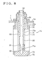
- Fig. 8 is a cross sectional view of a yet another evaporation source.
- Fig. 1 shows a principal part of an AIP device according to the present invention.
- Fig. 2 shows a work table being conveyed.
- Fig. 3 shows a top view of an AIP system using a traveling flat car.
- Fig. 4 shows
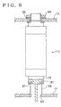
- FIG. 9 shows an electrical connecting means for a rod-shaped evaporation source.
- Fig. 10 shows an electrical connecting means for another rod-shaped evaporation source.
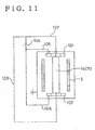
- Fig. 11 shows an anode corresponding to a rod-shaped evaporation source.
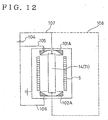
- Fig. 12 shows another anode corresponding to a rod-shaped evaporation source.
- Fig. 13 shows a further anode corresponding to a rod-shaped evaporation source.
- Fig. 14 shows yet another anode corresponding to a rod-shaped evaporation source.
- Fig. 15 is a connection diagram between a rod-shaped evaporation source and an anode, and a power supply.
- Fig. 16 is a connection diagram for an anode preheating.
- Fig. 16 is a connection diagram for an anode preheating.
- FIG. 17 is another connection diagram for an anode preheating.
- Fig. 18 is a driving system diagram for a work table and a rotary table.
- Fig. 19 is a top view of another AIP system using a traveling flat car.
- Fig. 20 is a top view of an AIP system using a rotary table.
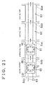
- Fig. 21 is a concept drawing showing the application of a shielding plate to an AIP device of an in-line system.
- Fig. 22 shows a principal part of a conventional AIP device.
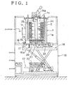
- FIG. 1 shows the principal part of an AIP device according to the present invention.
- a main body 1a of a vacuum chamber 1 is fixed on the second floor part 16 of a frame 15, and a discharge nozzle 1c is provided protrusively on the side surface of the main body 1a, and the bottom of it is opened.
- a lower lid 17 which is a lid body for opening and closing the opening portion of the main body 1a of the vacuum chamber 1 is supported elastically on a lifter 18 through a spring 18a, and following the ascent or descent of the lifter 18, it is able to ascend or descend between the lower position shown with a 2-dot chain line and the upper position shown with a full line.
- the vacuum chamber 1 is made to be air tight by a special seal.
- a rod-shaped evaporation source is protrusively provided downward from the center of an upper lid 1b of the vacuum chamber 1, and at the upper end of the rod-shaped evaporation source, an upper minus terminal 14a to be connected to the cathode of the arc power source (not shown in a drawing) is fixedly provided.
- a roller rail 20, a means for the horizontal movement of works 5, composed of a driven roller train, a lower minus terminal 21 to be connected to the cathode of the arc power source, and a driving gear 22 are provided on the lower lid 17.
- the work table 23 to be loaded with works 5 is placed on the lower lid 17 through the roller rail 20, and it can be conveyed in the thickness direction of the paper to your side rolling over the roller rail 20, and it can make the works 5 rotate and revolve with a driving gear 22.
- the lower lid 17 When the lower lid 17 is in the upper position shown with a full line, the lower minus terminal 21 is connected to the lower end of an evaporation source 14, and a continuous discharge is generated from the surface of the rod-shaped evaporation source 14 ranging in full length.
- a shielding plate 24 is loaded on the work table 23 and it is conveyed with the works 5.
- An anode (not shown in a drawing) corresponding to the rod-shaped evaporation source 14 can be loaded on the work table 23.
- a reference numeral, 25, shows a heater to be used for preheating works 5.
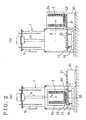
- FIG. 2(a) when the lower lid 17 is descended by the lift 18, the work table 23, placed on the roller rail 20, is descended in an arrow direction "c" in a state where it is loaded with the works 5, the shielding plate 24, and/or the anode, and the rod-shaped evaporation source 14 goes apart from the works 5.
- a reference numeral 30 is a traveling flat car, and a roller rail 31 is fixed to it.
- works 5 can be moved relatively for the rod-shaped evaporation source 14 in the axial direction of it (In the embodiment shown in Figs., 1 and 2, the relative movement in the vertical direction is performed by the ascent or descent of the lower lid 17 on which a work table 23 is placed.).
- the works 5 and the rod-shaped evaporation source 14 can be made to be apart from each other by an enough distance by the above-mentioned relative movement to be able to avoid the interference or collision between them.
- the work table 23 loaded with the works can be conveyed in the horizontal direction. Therefore, in an AIP device in which a rod-shaped evaporation source 14 is adopted, efficient handling of the works 5 by the work table 23 can be performed, which makes it possible to realize a device of high productivity.
- the rod-shaped evaporation source 14 is fixed to the main body 1a of the vacuum chamber 1, not to the work table 23. Thereby, it is made possible to avoid the problem which occurs when the rod-shaped evaporation source 14 is fixed to the work table 23 which moves up or down, such as the difficulties in installing a cooling device, etc. for the rod-shaped evaporation source.
- Metallic ions evaporated from a rod-shaped evaporation source irradiate the works 5 radially, so that the capture rate of vapor is higher in comparison with the capture rate in the case of a flat-shaped evaporation source, and the yield of about 80% can be expected.
- the yield in the case of a flat-shaped cathode 3 as shown in Fig. 23 is generally less than 50%. Since the rod-shaped evaporation source has a simple column shape or a cylinder shape, its weight can be several tens of kg, while the weight of the flat-shaped cathode shown in Fig.
- the mode of the relative movement of the works 5 for the rod-shaped evaporation source 14 is not limited to those in Figs., 1 and 2, and various kinds of modifications may be possible.
- the constitution may be such in which the main body 1a of the vacuum chamber 1 and the rod-shaped evaporation source 14 are moved for the works 5 and the lower lid 17. In the constitution shown in Fig.
- an upper lid 17a which hangs the works 5 is ascended from or descended to the main body 1a of the vacuum chamber 1 and the rod-shaped evaporation source 14.
- the vacuum chamber 1 is provided with a door (a portion written with a 2-dot chain line), which can be freely opened or closed, for taking in or taking out the works 5, and the rod-shaped evaporation source is ascended and descended with a small lid body 17C for the vacuum chamber 1.
- a door (a portion written with a 2-dot chain line), which can be freely opened or closed, for taking in or taking out the works 5
- the rod-shaped evaporation source is ascended and descended with a small lid body 17C for the vacuum chamber 1.
- a rod-shaped evaporation source 14 is provided protrusively in the horizontal direction on the main body 1a of the vacuum chamber 1 which is turned sideways, and for these mentioned in the above, a side lid 17B is moved together with the works 5 in the horizontal direction.
- a lid body which moves relatively for the main body 1a of the vacuum chamber 1 is not provided, and a relative movement is performed between the rod-shaped evaporation source and the works 5 in the vacuum chamber 1 to avoid the interference between the rod-shaped evaporation source 14 and the works 5, and after that, the works 5 are taken in or taken out through the door provided on the side surface of the vacuum chamber 1; in such a constitution, there is a problem that the vacuum chamber 1 may become a large sized one. Therefore, it is desirable that a lid body is provided on the main body 1a on the free end side of the rod-shaped evaporation source 14, and a relative movement is performed between the lid body and the main body 1a of the vacuum chamber 1.
- Figs. 5 to 8 are cross sectional views of a rod-shaped evaporation source to be applied to Fig. 1.
- a target member 71 of the rod-shaped evaporation source 14 is formed into a hollow cylinder.
- a lower arc confinement ring 72 having the same diameter as that of the target member 71 is fixed.
- a target supporting portion 73 on the upper end of the target member 71, and an upper arc confinement ring 74 which has the same outer diameter with the rod-shaped evaporation source is fixed on the outer periphery side of the target member 71.
- the description about the detailed constitution will be omitted.
- Center holes, 71a and 73a are provided in the target member 71, lower arc confinement ring 72, and the target holding portion 73, and the shaft 77 is inserted into these center holes.
- the target member 71 is fixed with a flange 75 of the shaft 77 and a nut 79 through the target holding portion 73. Owing to such a constitution in which the target member 71, the shaft 77 and the target holding portion 73 are fixed with one nut, the work for making screw holes on the target member to fix the flange 75 which holds the free end of the target can be omitted and also when the target member 71, a kind of the consumables, is to be changed, mounting/demounting of it can be performed easily.
- Fig. 6 shows an example of a constitution in which a rod-shaped evaporation source 14 shown in Fig. 5 heated by the power supplied from the arc power source can be efficiently cooled.
- the inner diameters of center holes, 71a, 72a and 73a, is larger than the outer diameter of the shaft 77, and an outer path 80 is formed on the shaft 77 on the side of the outer periphery 77a.
- a central path 81 is formed in the center of the shaft 77, and at an end of the central path a connecting port 83 for the input of a cooling medium is opened to be capable of being connected to an external piping, and the other end is closed.
- a lateral hole 82 which communicates with the outer path is opened on the closed end side of the central path, and a connecting port for discharge 84 is opened in a part of the target holding portion 73 along the outer path 80 being outside the main body 1a of the vacuum chamber 1.
- the cooling medium from the input connection port 83 flows from the upper part to the lower part through the central path 81 and passes the lateral path 82 and flows from the lower part to the upper part through the outer path 80 and reaches the discharge connecting port 84.
- the cooling medium from the input connection port 83 flows at a predetermined speed inside the central hole 71a of the target member without any stagnation, so that an efficient cooling with a high heat conductivity can be performed; thereby, the evaporation speed can be increased by supplying a large electric power to the rod-shaped evaporation source 14.
- Fig. 7 shows an example of a constitution of a rod-shaped evaporation source 14 which is able to absorb heat stress caused by a temperature difference.
- the shaft 77 which sends out a cooling medium to the tip of it, is in a low temperature, but the target member 71 is in a higher temperature than that of the shaft 77.
- the target member 71 elongates much in the axial direction but the shaft 77 elongates a little in the axial direction, so that a large compression stress is applied to the target member 71 and there has been a fear of breakage. Therefore, an elastic body, for example, a compression spring 78 is placed between the nut 79 for common clamping and the target holding portion 73 to make the compression spring 78 absorb the difference in heat expansion. Then, only a compression stress decided by the pressure given by the compression spring 78 is applied to the target member 71, so that there is no fear of breakage.
- a rubber plate, etc. can be used in place of the compression spring 78.
- Fig. 8 shows another example of a constitution for absorbing the heat stress.
- the shaft 77 is divided into several pieces in axial direction, and between the divided pieces, for example, a bellows 85 is inserted as an elastic body.
- the bellows 85 is something like a spring made with a plurality of plate springs connected mutually, and it generates a predetermined compressive force, and it can be a path for a cooling medium.
- a spring, a rubber plate, etc. can be used as an elastic body.
- the upper end of the evaporation source 14 is fixed with a nut 86 through an insulating member 96 on the main body 1a of the vacuum chamber 1, and the lower end of the evaporation source 14 is arranged to be a free end which can be detached by the open/close of the lower lid 17.
- the electrical connecting means is constituted with a plane member 87 which performs plane contact with the flange 75 of the shaft 77 and is provided in standing up on the lower lid 17 through an insulating member 97 and an elastic means (a flexible flange in Fig. 9).
- the plane member 87 corresponds to the lower minus terminal 21 in Fig. 1.
- the flexible flange 88 can be freely elongated or compressed bearing the inner pressure of the air and has a certain elasticity, and the inside of it communicates with the open air through an opening formed on the lower lid 17.
- the atmospheric pressure acts on the inside of the flexible flange 88 and presses the plane member 87 against the flange 75.
- Proper plane pressure can be secured on the plane contact portion owing to the atmospheric pressure and the elasticity of the flange 88 itself.
- the plane member 87 which is supported by the flexible flange 88 is capable of being parallel to the flange 75 to keep good contact to it; thereby, heating by a local contact can be avoided.
- the detachment of the electrical connection is performed with the downward movement of the lower lid 17.
- the plane member 87 is made to apart from the flange 75.
- the plane member is abutted against the flange 75 to form a plane contact portion, which makes it possible to supply a large current to the target member and to realize high productivity.
- the plane member 87 is made to be supported by a wide holding member 87a through an insulating member 97a, and when compression springs 90, for example 4 pieces of springs 90, are disposed on boundary positions between equally divided portions on a circle, the force of the compression springs 90 will contribute to the increase in the plane contact pressure. Further it is also possible to press the plane member 87 toward the flange 75 by providing a compression spring 90a on the lower end of the plane member 87 through an insulating member 98. Each of these springs can be used independently from each other, and if necessary, they can be used being combined as shown in the figure.
- Figs. 11 to 15 The examples of anode dispositions with which an approximately uniform arc in the axial direction can be obtained and still the degree of interruption for the works is small will be explained referring to Figs. 11 to 15.
- the examples shown in Figs., 11 to 14, are general examples of anode dispositions in the devices, in each of these devices an arc current is supplied from an end.
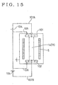
- the example shown in Fig. 15 is a concrete example in which the above-mentioned idea is applied to an AIP device in which an arc current is supplied from both ends of a rod-shaped evaporation source.
- ring shaped anodes, 101 and 102 are disposed in upper and lower symmetrical positions about the center of the target member, the positions are off the rod-shaped evaporation source, in particular, the target member 71.
- Both ring-shaped anodes, 101 and 102 are connected to a power supply 104 with wirings, 105 and 106, in parallel.
- An end of the rod-shaped evaporation source 14 is connected to the power supply 104 with a wiring 107.
- the ring-shaped anodes, 101 and 102, disposed in the symmetric positions upper and lower are effective to generate an arc being uniform in the axial direction of the evaporation source 14, and also the ring-shaped anodes, 102 and 103, do not make shadows on the works, which makes it possible to perform coating of works without unevenness.
- the figure as shown in with a broken line, in the case of a cathode side too, it is desirable to supply currents from both end parts. The same thing as described in the above can be said in the examples in Figs, 12, 13 and 14.
- the ring-shaped anodes, 101 and 102, shown in Fig. 11 are simple ring-shaped plates, but as shown in Fig. 12, when they are made to be ring-shaped anodes of dish types with conical surfaces, 101A and 102A, an arc generated on the surface of the target member 71 of the rod-shaped evaporation source 14 can be spread easily to the central part of the rod-shaped evaporation source 14, and the arc which is apt to be partial toward the end parts is controlled to be a uniform arc in the axial direction of the rod-shaped evaporation source 14.
- the anode 103 shown in Fig. 13 is composed of rods disposed in the equally divided portions on a circle divided by an arbitrary number, (In the example shown in the figure, the circle is divided into quarters.) the circle which is concentric with the rod-shaped evaporation source 14 being located between the rod-shaped evaporation source 14 and the works 5.
- Individual rods of the rod-shaped anode are connected to the power supply in parallel with wirings, 105 and 106.
- An end of the rod-shaped evaporation source 14 is connected to the power supply 104 with a wiring 107.
- the anode rods can be uniformly disposed in the radial direction and the axial direction, so that the partiality of an arc becomes small.
- the rod-shaped anode 103 is positioned between the rod-shaped evaporation source 14 and the works 5, so that the shadow is given to the works 5; however, the works 5 are arrange to revolve around the rod-shaped evaporation source 14 being rotated, so that the unevenness in the coating on the works 5 does not occur.
- the anode shown in Fig. 14 is a combined anode in which the ring-shaped anodes, 101 and 102, shown in Fig. 11, and the rod-shaped anode 103 shown in Fig. 13 are combined.
- the uniformity of arc in the axial direction is improved by the proper combination of anode constitutions.
- the rings and the rods are made into a unity, so that the wirings, 105 and 106, may be connected to the ring portion only.
- Fig. 15 shows an example in which the anode shown in Figs., 11 to 14, is applied to the rod-shaped evaporation source 14 of the present invention. Both ends of the rod-shaped evaporation source 14 are connected to the power supplies, 104 and 104, with wirings, 107A and 107B, respectively for the supply of arc currents.
- the rod-shaped anode 103 may be used as shown in the preceding page or a combination of them may be used.
- the rod-shaped anode 103 is applied to an AIP device according to the present invention, it is desirable to make an end free and use an electrical connecting means similar to the case of the rod-shaped evaporation source 14.
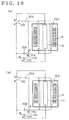
- Fig. 16 shows a state where the power supplies, 104 and 108, for an arc discharge are used as a power supply for preheating the rod-shaped anode 103.
- Fig. 16(a) shows a state of preheating
- Fig. 16(b) shows a state of electric discharge.
- changeover switches, 113, 114 and 115, and a bias circuit 116 are shown in the figure.
- Reference numerals, 104, 108, 113, 114, 115 and 116 constitute a preheating means. As shown in Fig.
- the switches, 113, 114 and 115 are changed over to "b" contact points to perform normal coating operation.
- the rod-shaped anode is kept in a high temperature, so that the film on the anode is not easily exfoliated or released.
- an AC power supply 110 to be used when the anode is utilized as a heater is provided separately from the DC power supplies, 104 and 108, to be used for the vacuum arc discharge.
- Switches, 111 and 112 are provided between the AC power supply circuit and the DC power supply circuit for changing over the connection to the rod-shaped anode 103.
- the switches, 111 and 112 are switched to "a" contact points, the rod-shaped anode 103 is connected to the DC power supplies, 104 and 108, for a normal coating operation.
- the rod-shaped anode Before the coating operation, when the switches, 111 and 112, are changed over to "b" contact points, the rod-shaped anode is connected to the AC power supply 110, and the works 5 are preheated by the rod-shaped anode 103 acting as a heater.
- the rod-shaped anode When a conventional flat-shaped evaporation source is used, the partiality of the arc can be reduced by providing a a rod-shaped anode in front of the flat-shaped evaporation source.
- the rod-shaped anode may be also used as a preheater as explained referring to Fig. 16 and Fig. 17.
- a roller rail is provided as a means for the horizontal movement; however, since the inside of the vacuum chamber 1 is evacuated, it is desirable to provide a constitution which makes secure vacuum seal possible and also makes secure driving of the work table 23 possible. Further, after the work table is conveyed into a predetermined position on the lower lid 17, the prevention of positional slippage in the horizontal direction is needed, independent of the up or down movement of the lower lid 17, from the point of view of stabilizing the contact of the electrical connecting means.
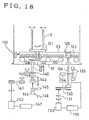
- a modification of a horizontal movement means of the work table 23 will be explained referring to Fig. 18.
- Fig. 18 an example of a means which rotates the works 5 on the work table 23 is shown together with the movement means of the work table 23. About the former, explanation will be given later.
- Free rollers 120 are provided on the lower lid 17, and the work table is arranged to roll over them.
- a rack 123 is stuck on the side surface of the work table 23, and a pinion 125 which is to be in gear with the rack 123 is engaged into the shaft 124 which is protrusively provided on the lower lid 17.
- the shaft 124 is provided for making the work table 23 move in the horizontal direction.
- the shaft 124 is connected to a driving motor 132 through a pair of pulleys 130 and a clutch 131.
- a disk brake 133 is provided on the shaft 124, and an encoder switch 134 is provided to detect the rotating position of the disk.
- the driving motor 132 is controlled by the driver 135, and the rotating information of the encoder switch 134 is input to the driver 135.
- the work table 23 is taken into the vacuum chamber by the pinion 125.
- a bias voltage transmission portion 150 to apply a bias voltage to the works 5 on the work table 23 is conveyed to a position where it is closely attached to the works 5 with a predetermined pressing force. In that position, when the shaft 124 is fixed by the disk brake 133 in the state where the pinion 125 is in gear with the rack 123, the work table is fixed at a predetermined position, and the bias voltage is securely transmitted to the works.
- a means which rotates the works 5 on the work table 23 will be explained.
- a rotary table 121 is supported freely rotatably with a shaft, and a rotating shaft 122 is protrusively provided extending up to be close to the bottom of the work table 23.
- a gear 126 is engaged with the rotating shaft 122, and a gear 128 to be in gear with the gear 126 is engaged with a shaft 127 which is protrusively provided.
- the shaft 127 is provided to rotate the rotary table 121, and it is connected to a driving motor 142 through a gear train 140 and a pulley 141.
- a ball joint 143 is provided on the lower end of the shaft 127, and after it is through with the rotation, it is connected to an air cylinder 144.
- the air cylinder 144 comprises limit switches, 145 and 146, for the upper and lower limits, and a vertical reciprocation is possible.
- the air cylinder 144 is contracted, and the gear 128 retreats to a position being lower than the gear 126.
- the air cylinder 144 is elongated, but whether the gear 128 and the gear 126 come into gear with each other or not is not certain.
- the contraction and the elongation of the air cylinder 144 are repeated several times in inching the driving motor 142 by the driver 147, the gear 128 and the gear 126 come into gear with each other.
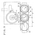
- the traveling flat car 30 comprises roller rails, 31 and 32, and a first loading portion A and a second loading portion B for placing work tables 23 are provided on it.
- the work table 23 are placed on a rail 33 being so arranged that they can reciprocate by the distance P' which is equal to the distance P between the first loading portion A and the second loading portion B.
- the traveling flat car 30 is in a position written with a full line and it waits in a state where the first loading portion A is vacant.
- a work table 23 loaded with processed works 5 is taken out in the direction (1) and the flat traveling car 30 travels by the distance P' in the direction (2) and it is positioned in a place shown with a 2-dot chain line, and the second loading portion B faces the vacuum chamber 1.
- a work table 23 loaded with unprocessed works 5 loaded on the second loading portion B is taken into the vacuum chamber 1 in the direction (3).
- the work table 23 is taken into the vacuum chamber 1 in the order of Fig. 2(b) - Fig. 2(a) - Fig. 1.
- the exchange of work tables is automatically performed, and a work table 23 loaded with processed works 5 is placed on the first loading portion A, and the second loading portion B is left in a vacant state. Only the work which has to done by a worker in a cycle time is to change the works 5 and the shielding plate 24 on the work table 23 on the first loading portion A.
- the above-mentioned rod-shaped anode 103 can be loaded on the work table 23, and in that case, it is desirable that the rod-shaped anode may have a constitution in which the exchange of the anodes is easy.
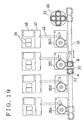
- Fig. 19 shows an AIP system in which a unit of flat car 30 is used for a plurality of AIP devices (4 devices in the figure).
- a reference numeral 37 is a switch board / control board
- 38 is a bias power supply unit
- 39 is an arc power supply unit
- 40 is a rack wiring.
- a worker places 4 work tables 23 loaded with unprocessed works 5 and clean shielding plates 24 on the turntable 36.
- the second loading portion B on the traveling flat car receives a work table 23 loaded with unprocessed works 5 from the turntable 36 and an automatic exchange of work tables is performed as shown in Fig. 3, and a work table loaded with processed works 5 is returned to the turntable 36.
- a worker will exchange works 5 and shielding plates 24 and, if necessary, rod-shaped anodes in a lot.
- Fig. 20 shows an AIP system in which a rotary table 40 is used in place of a traveling flat car.
- rotary tables, 40, --- 40 are provided, and respective rotary tables, 40, --- 40, are connected with both-way conveyers, 41, --- 41.
- a take-out conveyer 42 is connected to the opposite side of a both-way conveyer 41 of a rotary table 40 in front of the AIP device 35A, and a first stocker 45, which is able to store a plurality of work tables loaded with processed works 5, is connected to an end of the take-out conveyer 42 through a cross table 44.
- a take-in conveyer 43 is connected to the opposite side of a both-way conveyer 41 of a rotary table 40 in front of the AIP device 35X, and a second stocker 47, which is able to store a plurality of work tables loaded with unprocessed works 5, is connected to an end of the take-in conveyer 43 through a cross table 46.
- a work table 23 loaded with processed works 5 is taken out as indicated by an arrow mark (1)on a rotary table 40, and the rotary table 40 is turned and the work table 23 loaded with processed works 5 is sent out to a both way conveyer 41 in the direction shown with an arrow mark (2).
- the work table 23 loaded with processed works 5 passes through the rotary table 40 of the AIP device 35A and is stored in the first stocker 45 through the cross table 44.
- a work table 23 loaded with unprocessed works 5 is taken out from the second stocker 47 through a cross table 46 and taken into a turn table 40 in the direction (3), and the turn table 40 is turned and the work table 23 loaded with unprocessed works 5 is sent out in the direction (4).
- automatic exchanges of work tables, 35A, --- 35X, of AIP devices are performed in order.
- a work table 23 loaded with unprocessed works 5 or with processed works 5 can be conveyed automatically, so that an AIP device can be operated in the nighttime without an attendance of a worker, which makes it possible to realize high productivity.
- a shielding plate on a work table besides works 5 can be applied not only to an AIP device of a batch system as explained in the above, but also to an in-line system AIP device as shown in Fig. 21.
- a vacuum chamber 60, a preheating room 61/ a coating room 62 and a cooling room 63 are connected to each other through gate valves, 64a, 64b, 64c and 64d, and a work table 66 is conveyed in respective rooms, 60 to 63, in order on a rail 65.
- the take-in or take-out of works into or from the device can be easily performed, so that they have high productivity and they can be applied to various kinds of surface processing work, especially, they are effective in the process of bar-shaped works.
Abstract
Description
- The present invention relates to an arc ion plating device (hereinafter referred to as an AIP device), a coating device utilizing a vacuum arc discharge, and an arc ion plating system provided with the AIP device.
- An arc ion plating method is a method in which a vacuum arc discharge is generated between an anode and a cathode, a target, which are disposed in a vacuum chamber, and the cathode material is evaporated from the arc spots generated on the surface of the cathode, a solid body, and the vapor is accumulated on the surfaces of works disposed in the vacuum chamber to form a film on the works. AIP devices which realize an arc ion plating method are disclosed in Examined Japanese Patent Publication Nos. SHO 58-3033 and SHO 52-14690 by a snaper or suplef, and after that various kinds of improvements are done.
- With the increasing demand for the application of the arc ion plating method as a technique of coating component parts for mass produced products with a hard film (for example, piston rings), it is considered to be an important subject to perform the coating of component parts with a hard film with high productivity.
- As a conventional AIP device for realizing high productivity, for example, an AIP device in which a work to be coated with a film is placed on a work table which can be freely taken into or taken out from a vacuum chamber is known to the public.
- The basic constitution of such an AIP device as described in the above will be explained referring to Fig. 22. Fig. 22(a) is a plan view and Fig. 22(b) is a longitudinal cross sectional view. There are an
anode 2 and a flat-shaped evaporation source (a cathode) 3 which are fixedly provided and further works 5 which is placed on a work table 4 in avacuum chamber 1. Anarc power source 3a is connected to theanode 2 and theevaporation source 3, and when an arc discharge is generated between theanode 2 and theevaporation source 3 in a vacuum, a target material on the surface of theevaporation source 3 is instantaneously evaporated and spring out into a vacuum asmetallic ions 6. Themetallic ions 6 are accelerated by applying abias voltage 7 to theworks 5 and themetallic ions 6 are stuck to the surfaces of the works together with the reaction gas particles 8, and a fine hard film (TiN, TiC, TiCN, ZrN, Cr-N, etc.) is generated. The work table 4 has a built-in gear device which is to be in gear with adriving gear 9 for making thework 5 rotate in a direction "a" and at the same time the work table is also rotated to make thework 5 revolve. Ashielding plate 12 having an opening in the radiating direction of themetallic ions 6 is provided inside thevacuum chamber 1. - Further, the
vacuum chamber 1 comprises adoor 10 and arail 11. When thevacuum chamber 1 is released by thedoor 10, the work table 4 loaded withworks 5 can be taken out along therail 11 in the direction "c". - In the case of an AIP device, works are not handled one by one when they are taken into or taken out from the
vacuum chamber 1, but a plurality of works are loaded on a work table beforehand and they can be taken into or taken out from thevacuum chamber 1 in a lot, so that the period of time for loading the works on the work table can be saved much, which is much beneficial for obtaining high productivity. An AIP device in which a film material can be evaporated uniformly and at a high speed from a flat evaporation source is disclosed, for example, in Unexamined Japanese Patent Publication No. HEI 4-224671. In the AIP device, a plurality of arc power sources are provided and power is supplied to each of the evaporation sources from each of the power supplies independently, and a high productivity is expected by uniformalizing the consumption of evaporation sources and making a high power operation possible. - Further, there is an AIP device in which the evaporation source is a rod shaped one, which is devised as a device being applicable to the use for the component parts as piston rings of which high productivity is required. Such an AIP device is paid attention because of the reason that the vapor of a film material is generated radially from the rod shaped evaporation source, so that a large number of works can be coated simultaneously with one evaporation source in disposing works as if they surround the evaporation source. Therefore, if a film material can be evaporated from the rod shaped evaporation source uniformly and at a high speed, the realization of high productivity may be possible.
- In the case of an AIP device in which a rod shaped evaporation source is adopted works are disposed in the positions surrounding the evaporation source, so that, if the evaporation source is fixed in a vacuum chamber, when the works loaded on a work table are taken into or taken out from the vacuum chamber, the works and the evaporation source will interfere or collide with each other; therefore, it is impossible to take in or take out the works as shown in Fig. 22.
- Accordingly, it can be considered to mount the rod shaped evaporation source itself on a work table; in that case, however, even if the interference or collision between the works and the evaporation source can be avoided, the film coating operation of high productivity by highly efficient generation of vapor with a large current discharge was not obtained because of a constitutional reason of the device such as the difficulty in the constitution of a cooling means of the evaporation source.
- The AIP device disclosed in Unexamined Japanese Patent No. HEI 4-224671 is a device which corresponds only to a flat-shaped evaporation source, and nothing is mentioned about the application to an AIP device having a rod-shaped evaporation source.
- Further, in the case of an AIP device shown in Pig, 22, in general, the take-in or takeout of works is performed manually and also man power is indispensable for the exchange or the cleaning of the evaporation source, the anode or the shielding plate, and such a work is often performed simultaneously with the take-in or takeout of works. It requires comparatively a short period of time for the take-in or takeout of works but it requires much time for the exchange or cleaning of the evaporation source, the anode or the shielding plate, and moreover, since such a work cannot be performed in the nighttime, the whole AIP device has to be stopped for the execution of such a work. In other words, from the point of view of the operation rate, there is a problem for the realization of high productivity.
- Further, it is referred to the US patent No. 4,151,059 and the UK patent application No. 2,160,898 which relate to sputtering devices comprising a vacuum chamber which accommodates a rod-shaped target and works to be coated with a film. The sputtering devices are arranged such that the target and the works are capable of moving relative to each other in the axial direction of the target.
- It is an object of the present invention, to provide an AIP device and an AIP system with a rod-shaped evaporation source which is able to realize high productivity in handling works efficiently.
- The above object is solved by an AIP device according to
claim 1 and an AIP system according toclaim 16 with further developments set forth in the corresponding dependent claims. - In the present invention related to
claim 1, when works are taken into or taken out from the vacuum chamber, the works can be moved relatively for the rod-shaped evaporation source in the axial direction of the rod-shaped evaporation source. Therefore, even if a rod-shaped evaporation source is adopted, works can be taken in or taken out without any interference or collision between the works and the rod-shaped evaporation source. In the result, an AID device of high productivity can be realized in adopting a rod-shaped evaporation source and in processing a plurality works en masse. - In the present invention related to
claim 2, when works are taken into or taken out from the vacuum chamber, since the works can be moved up or down relatively for the rod-shaped evaporation source, works can be handled without any interference or collision between the works and the rod-shaped evaporation source. Since the rod-shaped evaporation source is fixed in the vacuum chamber, When a work table for loading works is to be installed or when a mechanism concerning the installation of the rod-shaped evaporation source is to be installed, for example, when a cooling device for the rod-shaped evaporation source is to be installed, there is no need to install them in a concentrated state. Therefore, an AIP device of high productivity can be realized without making the constitution of a device a complicated one. - In the present invention related to
claim 3, a function of the lower lid to go up or down for the main body of the vacuum chamber is added to the invention described inclaim 2. It the main body of the vacuum chamber is to be moved, the constitutions of auxiliary facilities of the AIP device, for example, the constitution of a discharge nozzle may become complicated; however, if the lower lid is moved up or down, the above-mentioned problem can be avoided. Therefore, an AIP device of high productivity with a simple constitution can be realized. - In the present invention related to
claim 4, following function is added to the present invention related to claim 3: works are moved horizontally after they are completely lowered in the outside of the main body of the vacuum chamber, so that works can be taken in or taken out without any interference or collision with the rod-shaped evaporation source. Therefore, efficient handling of works in an AIP device in which a rod-shaped evaporation source is adopted is made possible, which makes it possible to realize an AIP device of high productivity. - In the present invention related to
claim 5, following function is added to the present invention described in claim 4: works are handled on a work table and the work table is moved horizontally utilizing a rack and a pinion, so that works can be moved certainly. Thereby, in an AIP device of high productivity further accurate operation is made possible. - In the present invention related to
claim 6, following function is added to the present invention described in claim 4: a shielding plate in handled being loaded on a work table together with the works, so that even in a case where exchange or cleaning of the shielding plate is needed, it can be performed in the outside of the AIP device without stopping the operation of the device. Therefore, the operation of the AIP device can be continued independent of the exchange or cleaning of the shielding plate, which makes it possible to realize an AIP device of high productivity. - In the present invention related to
claim 7, following function is added to the present invention described in claim 6: an anode is also loaded on a work table, so that even when the exchange or cleaning of the anode is needed, similar to the case of the shielding plate, it can be performed in the outside without stopping the operation of the AIP device. Therefore, the operation of the AIP device can be continued independent of the exchange or the cleaning of the anode, which makes it possible to realize an AIP device of high productivity. - In the present invention related to
claim 1, an end of the rod-shaped evaporation source is fixed on either the main body or the lid body of the vacuum chamber and the other end is connected through an electrical connecting means which can be freely disconnected from the lid body or main body, so that even though the rod-shaped evoparation and the works are made to be movable relative to each other, the arc electric power can be supplied to the rod-shaped evaporation source from both end parts; thereby, a large current can be supplied to the rod-shaped evaporation source. Therefore, in an AIP device in which a rod-shaped evaporation source is adopted, high productivity can be realized by supplying a large arc electric power. - In the present invention described in claim 8, following function is added to the present invention described in claim 1: a plane member supported by an elastic means is used for the electric connecting means, so that even when an inclination occurs in the connecting portion between the rod-shaped evaporation source and the electric connecting means, secure connection between them can be kept. Therefore, an AIP device of high productivity can be securely realized by supplying a large arc electric power securely to the rod-shaped evaporation source.
- In the present invention related to
claim 9, following function is added to the present invention described inclaim 1, since the rod-shaped evaporation source has a constitution in which the target member is supported with a shaft, it is possible to constitute a rod-shaped evaporation source having a free end, no that even when the target member of the rod-shaped evaporation source is consumed and the exchange is needed, the exchange work can be performed easily, Therefore, the period of time necessary for the exchange of the target members of the rod-shaped evaporation sources can be shortened and the operation rate of the AIP device can be upgraded, which makes it possible to realize an AIP device of high productivity. - In the present invention related to
claim 10, following function is added to the present invention described in claim 1: since it is so arranged that a cooling medium can be passed through the inside of the rod-shaped evaporation source, even when the temperature of the rod-shaped evaporation source is raised by the supply of a large arc electric power, it can be efficiently cooled. Therefore, evaporation speed can be increased by the supply of a large arc electric power to the rod-shaped evaporation source, which makes it possible to realize an AIP device of high productivity. - In the present invention related to
claim 11, following function is added to the invention described in claim 10: the target member is supported with nuts through an elastic body, so that the difference in the heat expansion between the target member and the shaft caused by the supply of power to the rod-shaped evaporation source and cooling of it can be absorbed by the elastic body. Therefore, there is no fear of the breakage of the target member by the difference in heat expansion between the target member and the shaft, which makes it possible to realize an AIP device of high productivity. - In the present invention related to
claims 12 and 13, the anode is so arranged that no voltage difference is generated in the axial direction of the rod-shaped evaporation source, so that a uniform discharge in the axial direction can be generated. Therefore, a uniform coating can be executed, which makes it possible to realise an AIP device which is able to produce the coating of high quality. - In the present invention related to
claim 14, following function is added to the present invention described inclaims 12 and 13: since the arc power is supplied from both ends of the rod-shaped evaporation source, a large arc power can be supplied to the rod-shaped evaporation source, and there occurs no voltage difference in the axial direction of the rod-shaped evaporation source; thereby, a uniform discharge in the axial direction can be generated. Therefore, an AIP device of high productivity can be realized and the quality of the film on the surfaces of works can be further improved. - In the present invention related to claim 15, following function is added to the present invention described in claim 13: since the rod-shaped anode can be used as a heater for preheating works, there is no need to provide a heater separately, and further the quality of the film on the works is not influenced by the film material or water vapor in the air stuck to the rod-shaped anode. Therefore, the quality of the film on the works can be improved further.
- In the present invention described in
claims 16 to 18, since a work table loaded with works can be automatically taken into or taken out from an AIP device in an AIP system having more than a unit of AIP devices, there is no need to stop the operation of AIP devices in the nighttime. Therefore, it is made possible to realize an AIP device in which unattended operation in the nighttime is possible, operation rate is high, and productivity is high. - Fig. 1 shows a principal part of an AIP device according to the present invention. Fig. 2 shows a work table being conveyed. Fig. 3 shows a top view of an AIP system using a traveling flat car. Fig. 4 shows an example of a relative movement between works and a rod-shaped evaporation source. Fig. 5 is a cross sectional view of a rod-shaped evaporation source. Fig. 6 is a cross sectional view of another rod-shaped evaporation source. Fig. 7 is a cross sectional view of a further rod-shaped evaporation source. Fig. 8 is a cross sectional view of a yet another evaporation source. Fig. 9 shows an electrical connecting means for a rod-shaped evaporation source. Fig. 10 shows an electrical connecting means for another rod-shaped evaporation source. Fig. 11 shows an anode corresponding to a rod-shaped evaporation source. Fig. 12 shows another anode corresponding to a rod-shaped evaporation source. Fig. 13 shows a further anode corresponding to a rod-shaped evaporation source. Fig. 14 shows yet another anode corresponding to a rod-shaped evaporation source. Fig. 15 is a connection diagram between a rod-shaped evaporation source and an anode, and a power supply. Fig. 16 is a connection diagram for an anode preheating. Fig. 17 is another connection diagram for an anode preheating. Fig. 18 is a driving system diagram for a work table and a rotary table. Fig. 19 is a top view of another AIP system using a traveling flat car. Fig. 20 is a top view of an AIP system using a rotary table. Fig. 21 is a concept drawing showing the application of a shielding plate to an AIP device of an in-line system. Fig. 22 shows a principal part of a conventional AIP device.
- An embodiment according to the present invention will be explained referring to the drawings. Fig. 1 shows the principal part of an AIP device according to the present invention.
- In Fig. 1, a
main body 1a of avacuum chamber 1 is fixed on thesecond floor part 16 of aframe 15, and adischarge nozzle 1c is provided protrusively on the side surface of themain body 1a, and the bottom of it is opened. Alower lid 17 which is a lid body for opening and closing the opening portion of themain body 1a of thevacuum chamber 1 is supported elastically on alifter 18 through a spring 18a, and following the ascent or descent of thelifter 18, it is able to ascend or descend between the lower position shown with a 2-dot chain line and the upper position shown with a full line. When thelower lid 17 is in the upper position, thevacuum chamber 1 is made to be air tight by a special seal. When thelower lid 17 is supported through an elastic body such as a spring 18a, it is easier to obtain a complete air tight state. A rod-shaped evaporation source is protrusively provided downward from the center of anupper lid 1b of thevacuum chamber 1, and at the upper end of the rod-shaped evaporation source, an upper minus terminal 14a to be connected to the cathode of the arc power source (not shown in a drawing) is fixedly provided. Aroller rail 20, a means for the horizontal movement ofworks 5, composed of a driven roller train, alower minus terminal 21 to be connected to the cathode of the arc power source, and adriving gear 22 are provided on thelower lid 17. The work table 23 to be loaded withworks 5 is placed on thelower lid 17 through theroller rail 20, and it can be conveyed in the thickness direction of the paper to your side rolling over theroller rail 20, and it can make theworks 5 rotate and revolve with adriving gear 22. When thelower lid 17 is in the upper position shown with a full line, thelower minus terminal 21 is connected to the lower end of anevaporation source 14, and a continuous discharge is generated from the surface of the rod-shapedevaporation source 14 ranging in full length. A shieldingplate 24 is loaded on the work table 23 and it is conveyed with theworks 5. An anode (not shown in a drawing) corresponding to the rod-shapedevaporation source 14 can be loaded on the work table 23. A reference numeral, 25, shows a heater to be used for preheating works 5. - Next, a conveyance procedure of the work table 23 in an AIP device having a constitution as described in the above will be explained referring to Fig. 2.
- At first, in Fig. 2(a), when the
lower lid 17 is descended by thelift 18, the work table 23, placed on theroller rail 20, is descended in an arrow direction "c" in a state where it is loaded with theworks 5, the shieldingplate 24, and/or the anode, and the rod-shapedevaporation source 14 goes apart from theworks 5. Areference numeral 30 is a traveling flat car, and aroller rail 31 is fixed to it. - In succession to the above, in Fig. 2(b), the work table 23 is taken out as shown by an arrow "d" onto the traveling
flat car 30 driven by the roller rails, 20 and 31. It is possible to make themain body 1a of thevacuum chamber 1 descend or ascend without making thelower lid 17 descend or ascend (On this point, detailed explanation will be given later.); however in that case, the constitution of the device becomes complicated, for example, a flexible hose has to be connected to thedischarge nozzle 1c, etc., so that it is desirable to make the lower lid descend or ascend. - In the AIP device as described in the above, works 5 can be moved relatively for the rod-shaped
evaporation source 14 in the axial direction of it (In the embodiment shown in Figs., 1 and 2, the relative movement in the vertical direction is performed by the ascent or descent of thelower lid 17 on which a work table 23 is placed.). When the work table 23 is moved horizontally being loaded withworks 5, theworks 5 and the rod-shapedevaporation source 14 can be made to be apart from each other by an enough distance by the above-mentioned relative movement to be able to avoid the interference or collision between them. After that the work table 23 loaded with the works can be conveyed in the horizontal direction. Therefore, in an AIP device in which a rod-shapedevaporation source 14 is adopted, efficient handling of theworks 5 by the work table 23 can be performed, which makes it possible to realize a device of high productivity. - Further, the rod-shaped
evaporation source 14 is fixed to themain body 1a of thevacuum chamber 1, not to the work table 23. Thereby, it is made possible to avoid the problem which occurs when the rod-shapedevaporation source 14 is fixed to the work table 23 which moves up or down, such as the difficulties in installing a cooling device, etc. for the rod-shaped evaporation source. - In a case where a device is so constituted that the shielding
plate 24 and the anode are conveyed on the work table 23 together with theworks 5, when it is necessary to exchange or clean the shieldingplate 24 or the anode, such a work can be performed outside the AIP device, so that there is no need to stop the operation of the device for such a work, which makes it possible to realize a device of high productivity. The above-mentioned constitution can be applied to a conventional AIP device using a flat-shaped evaporation source. - Metallic ions evaporated from a rod-shaped evaporation source irradiate the
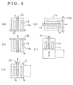
works 5 radially, so that the capture rate of vapor is higher in comparison with the capture rate in the case of a flat-shaped evaporation source, and the yield of about 80% can be expected. The yield in the case of a flat-shapedcathode 3 as shown in Fig. 23 is generally less than 50%. Since the rod-shaped evaporation source has a simple column shape or a cylinder shape, its weight can be several tens of kg, while the weight of the flat-shaped cathode shown in Fig. 23 is several kg at the maximum, so that the manufacturing cost of a target member, in the case of a rod-shapedevaporation source 14 is expected to be less than 1/4 in comparison with the cost in the past. The effective cost per gram of the target can be remarkably reduced. The mode of the relative movement of theworks 5 for the rod-shapedevaporation source 14 is not limited to those in Figs., 1 and 2, and various kinds of modifications may be possible. For example, as shown in Fig. 4(a), the constitution may be such in which themain body 1a of thevacuum chamber 1 and the rod-shapedevaporation source 14 are moved for theworks 5 and thelower lid 17. In the constitution shown in Fig. 4(b), an upper lid 17a which hangs theworks 5 is ascended from or descended to themain body 1a of thevacuum chamber 1 and the rod-shapedevaporation source 14. In the constitution shown in Fig. 4(c), thevacuum chamber 1 is provided with a door (a portion written with a 2-dot chain line), which can be freely opened or closed, for taking in or taking out theworks 5, and the rod-shaped evaporation source is ascended and descended with asmall lid body 17C for thevacuum chamber 1. In the constitution shown in Fig. 4(d), a rod-shapedevaporation source 14 is provided protrusively in the horizontal direction on themain body 1a of thevacuum chamber 1 which is turned sideways, and for these mentioned in the above, aside lid 17B is moved together with theworks 5 in the horizontal direction. - In the constitutions shown in Fig. 1 and Figs., 4(a), 4(b), 4(c) and 4(d), in the case of a relative movement of the rod-shaped
evaporation source 14 or the lid bodies (lower lid 17,upper lid 17A andside lid 17B), an opening portion is provided on thevacuum chamber 1 on the free end side of the rod-shapedevaporation source 14, and a relative movement is performed between the lid body at the opening portion and themain body 1a of thevacuum chamber 1. On the other hand, in the constitution shown in Fig. 4(e), a lid body which moves relatively for themain body 1a of thevacuum chamber 1 is not provided, and a relative movement is performed between the rod-shaped evaporation source and theworks 5 in thevacuum chamber 1 to avoid the interference between the rod-shapedevaporation source 14 and theworks 5, and after that, theworks 5 are taken in or taken out through the door provided on the side surface of thevacuum chamber 1; in such a constitution, there is a problem that thevacuum chamber 1 may become a large sized one. Therefore, it is desirable that a lid body is provided on themain body 1a on the free end side of the rod-shapedevaporation source 14, and a relative movement is performed between the lid body and themain body 1a of thevacuum chamber 1. - As described in the above, an end of the rod-shaped
evaporation source 14 is an fixed end and the other end is an free end. Various kinds of examples of such rod-shaped evaporation sources will be explained referring to Figs. 5 to 8. Figs. 5 to 8 are cross sectional views of a rod-shaped evaporation source to be applied to Fig. 1. - In Fig. 5, a
target member 71 of the rod-shapedevaporation source 14 is formed into a hollow cylinder. On the lower end of thetarget member 71, a lowerarc confinement ring 72 having the same diameter as that of thetarget member 71 is fixed. There is atarget supporting portion 73 on the upper end of thetarget member 71, and an upperarc confinement ring 74 which has the same outer diameter with the rod-shaped evaporation source is fixed on the outer periphery side of thetarget member 71. In order to insulate the arc confinement rings, 72 and 74, from the target member they are fixed to thetarget holding portion 73 orshaft 77 through insulators, but the description about the detailed constitution will be omitted. Center holes, 71a and 73a, are provided in thetarget member 71, lowerarc confinement ring 72, and thetarget holding portion 73, and theshaft 77 is inserted into these center holes. Thetarget member 71 is fixed with aflange 75 of theshaft 77 and anut 79 through thetarget holding portion 73. Owing to such a constitution in which thetarget member 71, theshaft 77 and thetarget holding portion 73 are fixed with one nut, the work for making screw holes on the target member to fix theflange 75 which holds the free end of the target can be omitted and also when thetarget member 71, a kind of the consumables, is to be changed, mounting/demounting of it can be performed easily. - Fig. 6 shows an example of a constitution in which a rod-shaped
evaporation source 14 shown in Fig. 5 heated by the power supplied from the arc power source can be efficiently cooled. The inner diameters of center holes, 71a, 72a and 73a, is larger than the outer diameter of theshaft 77, and anouter path 80 is formed on theshaft 77 on the side of theouter periphery 77a. Acentral path 81 is formed in the center of theshaft 77, and at an end of the central path a connectingport 83 for the input of a cooling medium is opened to be capable of being connected to an external piping, and the other end is closed. Alateral hole 82 which communicates with the outer path is opened on the closed end side of the central path, and a connecting port fordischarge 84 is opened in a part of thetarget holding portion 73 along theouter path 80 being outside themain body 1a of thevacuum chamber 1. The cooling medium from theinput connection port 83 flows from the upper part to the lower part through thecentral path 81 and passes thelateral path 82 and flows from the lower part to the upper part through theouter path 80 and reaches thedischarge connecting port 84. The cooling medium from theinput connection port 83 flows at a predetermined speed inside thecentral hole 71a of the target member without any stagnation, so that an efficient cooling with a high heat conductivity can be performed; thereby, the evaporation speed can be increased by supplying a large electric power to the rod-shapedevaporation source 14. - Fig. 7 shows an example of a constitution of a rod-shaped
evaporation source 14 which is able to absorb heat stress caused by a temperature difference. Theshaft 77, which sends out a cooling medium to the tip of it, is in a low temperature, but thetarget member 71 is in a higher temperature than that of theshaft 77. Thetarget member 71 elongates much in the axial direction but theshaft 77 elongates a little in the axial direction, so that a large compression stress is applied to thetarget member 71 and there has been a fear of breakage. Therefore, an elastic body, for example, acompression spring 78 is placed between thenut 79 for common clamping and thetarget holding portion 73 to make thecompression spring 78 absorb the difference in heat expansion. Then, only a compression stress decided by the pressure given by thecompression spring 78 is applied to thetarget member 71, so that there is no fear of breakage. A rubber plate, etc. can be used in place of thecompression spring 78. - Fig. 8 shows another example of a constitution for absorbing the heat stress. The
shaft 77 is divided into several pieces in axial direction, and between the divided pieces, for example, a bellows 85 is inserted as an elastic body. The bellows 85 is something like a spring made with a plurality of plate springs connected mutually, and it generates a predetermined compressive force, and it can be a path for a cooling medium. When it is applied to a rod-shapedevaporation source 14 as shown in Fig. 5 in which paths for cooling medium are not provided, a spring, a rubber plate, etc. can be used as an elastic body. - In order to realize an AIP device of high productivity, it is necessary to supply a large arc current to the evaporation source and to generate a continuous arc. In order to supply a large arc current to a rod-shaped evaporation source and to generate a continuous arc, it is very effective to supply an arc current from both ends of the rod-shaped evaporation source. Since the lower end of the rod-shaped
evaporation source 14 according to the present invention described in the above is a free end, an electrical connecting means which can be freely disconnected is provided on the lower end of it to supply an arc current from both ends of the rod-shaped evaporation source 14 (through upper and lower minus terminals, 14a and 21. in Fig. 1). The example of the electrical connecting means will be explained referring to Figs. 9 and 10. - In Fig. 9, the upper end of the
evaporation source 14 is fixed with anut 86 through an insulatingmember 96 on themain body 1a of thevacuum chamber 1, and the lower end of theevaporation source 14 is arranged to be a free end which can be detached by the open/close of thelower lid 17. The electrical connecting means is constituted with aplane member 87 which performs plane contact with theflange 75 of theshaft 77 and is provided in standing up on thelower lid 17 through an insulatingmember 97 and an elastic means (a flexible flange in Fig. 9). Theplane member 87 corresponds to thelower minus terminal 21 in Fig. 1. Theflexible flange 88 can be freely elongated or compressed bearing the inner pressure of the air and has a certain elasticity, and the inside of it communicates with the open air through an opening formed on thelower lid 17. When the inside of themain body 1a of thevacuum chamber 1 is evacuated, the atmospheric pressure acts on the inside of theflexible flange 88 and presses theplane member 87 against theflange 75. Proper plane pressure can be secured on the plane contact portion owing to the atmospheric pressure and the elasticity of theflange 88 itself. Even when the rod-shapedevaporation source 14 is slanted a little and theflange 75 is not placed horizontally, theplane member 87 which is supported by theflexible flange 88 is capable of being parallel to theflange 75 to keep good contact to it; thereby, heating by a local contact can be avoided. In the embodiment explained in Fig. 4, the detachment of the electrical connection is performed with the downward movement of thelower lid 17. When thelower lid 17 is moved downward, theplane member 87 is made to apart from theflange 75. When thelower lid 17 is moved upward the plane member is abutted against theflange 75 to form a plane contact portion, which makes it possible to supply a large current to the target member and to realize high productivity. - In order to make a large current flow, a large plane pressure is needed in the plane contact portion, and if such a large plane pressure could not be obtained in the constitution as shown in Fig. 9, an additional elastic means can be used as shown in Fig. 10. In other words, the
plane member 87 is made to be supported by awide holding member 87a through an insulatingmember 97a, and when compression springs 90, for example 4 pieces ofsprings 90, are disposed on boundary positions between equally divided portions on a circle, the force of the compression springs 90 will contribute to the increase in the plane contact pressure. Further it is also possible to press theplane member 87 toward theflange 75 by providing acompression spring 90a on the lower end of theplane member 87 through an insulatingmember 98. Each of these springs can be used independently from each other, and if necessary, they can be used being combined as shown in the figure. - As described in the above, high productivity can be realized by making a large arc current flow through the rod-shaped evaporation source in the constitution as shown in Figs. 9 and 10. When a uniform arc is not generated in the axial direction of the rod-shaped evaporation source, unevenness in the coating of works occurs; thereby, it is effective to devise the disposition of an anode for the rod-shaped evaporation source. In a case where an anode is disposed around the evaporation source, the anode can make a shadow on the works disturbing the metallic ions emitted toward the works, so that it is necessary to pay attention to the disposition of an anode not to affect much influence on the works. The examples of anode dispositions with which an approximately uniform arc in the axial direction can be obtained and still the degree of interruption for the works is small will be explained referring to Figs. 11 to 15. The examples shown in Figs., 11 to 14, are general examples of anode dispositions in the devices, in each of these devices an arc current is supplied from an end. The example shown in Fig. 15 is a concrete example in which the above-mentioned idea is applied to an AIP device in which an arc current is supplied from both ends of a rod-shaped evaporation source.
- In Fig. 11, ring shaped anodes, 101 and 102, are disposed in upper and lower symmetrical positions about the center of the target member, the positions are off the rod-shaped evaporation source, in particular, the
target member 71. Both ring-shaped anodes, 101 and 102, are connected to apower supply 104 with wirings, 105 and 106, in parallel. An end of the rod-shapedevaporation source 14 is connected to thepower supply 104 with awiring 107. In the constitution as described in the above, the ring-shaped anodes, 101 and 102, disposed in the symmetric positions upper and lower are effective to generate an arc being uniform in the axial direction of theevaporation source 14, and also the ring-shaped anodes, 102 and 103, do not make shadows on the works, which makes it possible to perform coating of works without unevenness. In the figure, as shown in with a broken line, in the case of a cathode side too, it is desirable to supply currents from both end parts. The same thing as described in the above can be said in the examples in Figs, 12, 13 and 14. - The ring-shaped anodes, 101 and 102, shown in Fig. 11 are simple ring-shaped plates, but as shown in Fig. 12, when they are made to be ring-shaped anodes of dish types with conical surfaces, 101A and 102A, an arc generated on the surface of the
target member 71 of the rod-shapedevaporation source 14 can be spread easily to the central part of the rod-shapedevaporation source 14, and the arc which is apt to be partial toward the end parts is controlled to be a uniform arc in the axial direction of the rod-shapedevaporation source 14. - The
anode 103 shown in Fig. 13 is composed of rods disposed in the equally divided portions on a circle divided by an arbitrary number, (In the example shown in the figure, the circle is divided into quarters.) the circle which is concentric with the rod-shapedevaporation source 14 being located between the rod-shapedevaporation source 14 and theworks 5. Individual rods of the rod-shaped anode are connected to the power supply in parallel with wirings, 105 and 106. An end of the rod-shapedevaporation source 14 is connected to thepower supply 104 with awiring 107. In the case of the rod-shapedanode 103, the anode rods can be uniformly disposed in the radial direction and the axial direction, so that the partiality of an arc becomes small. The rod-shapedanode 103 is positioned between the rod-shapedevaporation source 14 and theworks 5, so that the shadow is given to theworks 5; however, theworks 5 are arrange to revolve around the rod-shapedevaporation source 14 being rotated, so that the unevenness in the coating on theworks 5 does not occur. In the present example, it is also desirable to supply the power from both end parts of the cathode with awiring 108. - The anode shown in Fig. 14 is a combined anode in which the ring-shaped anodes, 101 and 102, shown in Fig. 11, and the rod-shaped
anode 103 shown in Fig. 13 are combined. The uniformity of arc in the axial direction is improved by the proper combination of anode constitutions. The rings and the rods are made into a unity, so that the wirings, 105 and 106, may be connected to the ring portion only. - Fig. 15 shows an example in which the anode shown in Figs., 11 to 14, is applied to the rod-shaped
evaporation source 14 of the present invention. Both ends of the rod-shapedevaporation source 14 are connected to the power supplies, 104 and 104, with wirings, 107A and 107B, respectively for the supply of arc currents. According to such a constitution as described in the above, large arc currents are supplied from both ends of the rod-shapedevaporation source 14, which contributes high productivity of the device, and also the potential difference in the axial direction of the rod-shapedevaporation source 14 is decreased, and further the effect explained in Figs., 11 to 14, is added to it, so that the uniformity of an arc in the axial direction can be improved further. In a device according to Fig. 15, the currents which flow through both end parts of the evaporation source and the anode can be controlled more precisely, which makes it possible to achieve more accurate uniformity of an arc. - In the constitution of an anode, besides the ring-shaped anodes, 101 and 102, as shown in Fig. 15, the rod-shaped
anode 103 may be used as shown in the preceding page or a combination of them may be used. When the rod-shapedanode 103 is applied to an AIP device according to the present invention, it is desirable to make an end free and use an electrical connecting means similar to the case of the rod-shapedevaporation source 14. - In a case where a rod-shaped
anode 103 is used which is disposed between the rod-shapedevaporation source 14 and theworks 5, a lot of film material is attached to the rods. Since the rod-shaped anode is kept in a low temperature by water cooling, the attached film can be exfoliated or separated, or the moisture in the atmosphere, etc. attached on the film on the anode while thevacuum chamber 1 is opened to the atmosphere can be released, which may exert a baneful influence on the quality of the film on the works. Therefore, it is desirable to release the moisture, etc. attached on the surface of the rod-shapedanode 103 by utilizing it as a heater for preheating theworks 5 before the coating operation is started, and to keep the anode in a high temperature to control the exfoliation or separation of the film on the anode in the coating operation. - Fig. 16 shows a state where the power supplies, 104 and 108, for an arc discharge are used as a power supply for preheating the rod-shaped
anode 103. Fig. 16(a) shows a state of preheating, and Fig. 16(b) shows a state of electric discharge. In addition to a circuit necessary for electric discharge, changeover switches, 113, 114 and 115, and abias circuit 116 are shown in the figure. Reference numerals, 104, 108, 113, 114, 115 and 116 constitute a preheating means. As shown in Fig. 16(a), when theswitches anode 103 in parallel, and the rod-shaped anode is used as a heater for preheating theworks 5. Therefore, it is not needed to provide a heater separately, and also the moisture, etc. attached on the film of the rod-shapedanode 103 can be released in a preheating operation, so that it makes possible to avoid a baneful influence caused by the release of the moisture, etc. in a coating operation which exerts on the quality of the film on awork 5. When the preheating is finished, the switches, 113, 114 and 115, are changed over to "b" contact points to perform normal coating operation. During the coating operation the rod-shaped anode is kept in a high temperature, so that the film on the anode is not easily exfoliated or released. - In Fig. 17, an
AC power supply 110 to be used when the anode is utilized as a heater is provided separately from the DC power supplies, 104 and 108, to be used for the vacuum arc discharge. Switches, 111 and 112, are provided between the AC power supply circuit and the DC power supply circuit for changing over the connection to the rod-shapedanode 103. When the switches, 111 and 112, are switched to "a" contact points, the rod-shapedanode 103 is connected to the DC power supplies, 104 and 108, for a normal coating operation. Before the coating operation, when the switches, 111 and 112, are changed over to "b" contact points, the rod-shaped anode is connected to theAC power supply 110, and theworks 5 are preheated by the rod-shapedanode 103 acting as a heater. When a conventional flat-shaped evaporation source is used, the partiality of the arc can be reduced by providing a a rod-shaped anode in front of the flat-shaped evaporation source. In such a case, the rod-shaped anode may be also used as a preheater as explained referring to Fig. 16 and Fig. 17. - As described in the explanation of Fig. 1 and Fig. 2, when the
works 5 are taken out, the work table 23 can be moved horizontally on thelower lid 17. In the embodiment shown in Fig. 1 and Fig. 2, a roller rail is provided as a means for the horizontal movement; however, since the inside of thevacuum chamber 1 is evacuated, it is desirable to provide a constitution which makes secure vacuum seal possible and also makes secure driving of the work table 23 possible. Further, after the work table is conveyed into a predetermined position on thelower lid 17, the prevention of positional slippage in the horizontal direction is needed, independent of the up or down movement of thelower lid 17, from the point of view of stabilizing the contact of the electrical connecting means. - Therefore, a modification of a horizontal movement means of the work table 23 will be explained referring to Fig. 18. In Fig. 18, an example of a means which rotates the
works 5 on the work table 23 is shown together with the movement means of the work table 23. About the former, explanation will be given later. -
Free rollers 120 are provided on thelower lid 17, and the work table is arranged to roll over them. Arack 123 is stuck on the side surface of the work table 23, and apinion 125 which is to be in gear with therack 123 is engaged into theshaft 124 which is protrusively provided on thelower lid 17. Theshaft 124 is provided for making the work table 23 move in the horizontal direction. Theshaft 124 is connected to a drivingmotor 132 through a pair ofpulleys 130 and a clutch 131. Adisk brake 133 is provided on theshaft 124, and anencoder switch 134 is provided to detect the rotating position of the disk. The drivingmotor 132 is controlled by thedriver 135, and the rotating information of theencoder switch 134 is input to thedriver 135. The work table 23 is taken into the vacuum chamber by thepinion 125. In the last step, a biasvoltage transmission portion 150 to apply a bias voltage to theworks 5 on the work table 23 is conveyed to a position where it is closely attached to theworks 5 with a predetermined pressing force. In that position, when theshaft 124 is fixed by thedisk brake 133 in the state where thepinion 125 is in gear with therack 123, the work table is fixed at a predetermined position, and the bias voltage is securely transmitted to the works. - When the work table 23 is taken in, in some case, the
rack 123 and thepinion 125 collide with each other and not engaged with each other. Therefore, when the work table is taken out, the angle of rotation at the position where thepinion 125 is separated from therack 123 is stored in thedriver 135 through anencoder switch 134. When it is taken in, the clutch 131 is made ON and the drivingmotor 132 is operated to make the angle of rotation be equal to the stored value and the clutch is made OFF. Then, therack 123 on the work table 23, which is pushed in by other driving means, can be engaged smoothly with thepinion 125. - Next, a means which rotates the
works 5 on the work table 23 will be explained. On the work table 23, a rotary table 121 is supported freely rotatably with a shaft, and arotating shaft 122 is protrusively provided extending up to be close to the bottom of the work table 23. Agear 126 is engaged with therotating shaft 122, and a gear 128 to be in gear with thegear 126 is engaged with ashaft 127 which is protrusively provided. Theshaft 127 is provided to rotate the rotary table 121, and it is connected to a drivingmotor 142 through agear train 140 and apulley 141. A ball joint 143 is provided on the lower end of theshaft 127, and after it is through with the rotation, it is connected to anair cylinder 144. Theair cylinder 144 comprises limit switches, 145 and 146, for the upper and lower limits, and a vertical reciprocation is possible. When a work table is taken in or taken out, theair cylinder 144 is contracted, and the gear 128 retreats to a position being lower than thegear 126. When the work table 23 is fixed at a predetermined position, theair cylinder 144 is elongated, but whether the gear 128 and thegear 126 come into gear with each other or not is not certain. When the contraction and the elongation of theair cylinder 144 are repeated several times in inching the drivingmotor 142 by thedriver 147, the gear 128 and thegear 126 come into gear with each other. - When the horizontal movement means and the rotating means for
works 5 are constituted as described in the above, only 2 shafts, 124 and 127, are provided protrusively on thelower lid 17, so that vacuum seal is needed only in these parts, which makes it possible to perform vacuum seal securely. Because of the use of therack 123 and thepinion 125, the drive for the work table 23 can be performed securely, and also a work table can be fixed by fixing theshaft 124 into which thepinion 125 is engaged. The horizontal movement means of a work table 23 and the rotating means of theworks 5 can be applied to a conventional AIP device with a flat evaporation source. - Next, the AIP system to perform an automatic exchange of the above-mentioned work tables 23 will be explained referring to Fig. 3. The traveling
flat car 30 comprises roller rails, 31 and 32, and a first loading portion A and a second loading portion B for placing work tables 23 are provided on it. The work table 23 are placed on arail 33 being so arranged that they can reciprocate by the distance P' which is equal to the distance P between the first loading portion A and the second loading portion B. In the case of an automatic exchange of work tables 23, the travelingflat car 30 is in a position written with a full line and it waits in a state where the first loading portion A is vacant. Then, a work table 23 loaded with processedworks 5 is taken out in the direction (1) and the flat travelingcar 30 travels by the distance P' in the direction (2) and it is positioned in a place shown with a 2-dot chain line, and the second loading portion B faces thevacuum chamber 1. Then, a work table 23 loaded withunprocessed works 5 loaded on the second loading portion B is taken into thevacuum chamber 1 in the direction (3). The work table 23 is taken into thevacuum chamber 1 in the order of Fig. 2(b) - Fig. 2(a) - Fig. 1. When a worker works till he places the work table 23 loaded with unprocessed works on the second loading portion B, the exchange of work tables is automatically performed, and a work table 23 loaded with processedworks 5 is placed on the first loading portion A, and the second loading portion B is left in a vacant state. Only the work which has to done by a worker in a cycle time is to change theworks 5 and the shieldingplate 24 on the work table 23 on the first loading portion A. The above-mentioned rod-shapedanode 103 can be loaded on the work table 23, and in that case, it is desirable that the rod-shaped anode may have a constitution in which the exchange of the anodes is easy. - Fig. 19 shows an AIP system in which a unit of
flat car 30 is used for a plurality of AIP devices (4 devices in the figure). Four units of AIP devices, 35A, 35B, 35C and 35D are placed in order along therail 33, and a turn table 36 is provided at an end of therail 33. Areference numeral 37 is a switch board / control board, 38 is a bias power supply unit, 39 is an arc power supply unit, and 40 is a rack wiring. A worker places 4 work tables 23 loaded withunprocessed works 5 andclean shielding plates 24 on theturntable 36. When the process of works on a specific AIP device becomes close to an end, the second loading portion B on the traveling flat car receives a work table 23 loaded withunprocessed works 5 from theturntable 36 and an automatic exchange of work tables is performed as shown in Fig. 3, and a work table loaded with processedworks 5 is returned to theturntable 36. As described in the above, when the cycles of respective AIP devices are finished, there remains a state where work tables loaded with processedworks 5 are on the turn table. Then, a worker will exchangeworks 5 and shieldingplates 24 and, if necessary, rod-shaped anodes in a lot. In the example shown in Fig. 3 and Fig. 19, 2 work table loading portions are provided; however, a system as shown below is also good: there is only one loading portion, and at first, it receives a work table loaded with processed works, and after it is conveyed to aturntable 36, it receives a work table loaded with unprocessed works and convey it to the AIP device. - Fig. 20 shows an AIP system in which a rotary table 40 is used in place of a traveling flat car. In front of respective AIP devices, 35A, --- 35X, rotary tables, 40, --- 40, are provided, and respective rotary tables, 40, --- 40, are connected with both-way conveyers, 41, --- 41. A take-out
conveyer 42 is connected to the opposite side of a both-way conveyer 41 of a rotary table 40 in front of theAIP device 35A, and afirst stocker 45, which is able to store a plurality of work tables loaded with processedworks 5, is connected to an end of the take-outconveyer 42 through a cross table 44. Further, a take-inconveyer 43 is connected to the opposite side of a both-way conveyer 41 of a rotary table 40 in front of theAIP device 35X, and asecond stocker 47, which is able to store a plurality of work tables loaded withunprocessed works 5, is connected to an end of the take-inconveyer 43 through a cross table 46. For example, when an automatic exchange in anAIP 35X is needed, a work table 23 loaded with processedworks 5 is taken out as indicated by an arrow mark (1)on a rotary table 40, and the rotary table 40 is turned and the work table 23 loaded with processedworks 5 is sent out to a bothway conveyer 41 in the direction shown with an arrow mark (2). The work table 23 loaded with processedworks 5 passes through the rotary table 40 of theAIP device 35A and is stored in thefirst stocker 45 through the cross table 44. On the other hand, a work table 23 loaded withunprocessed works 5 is taken out from thesecond stocker 47 through a cross table 46 and taken into a turn table 40 in the direction (3), and the turn table 40 is turned and the work table 23 loaded withunprocessed works 5 is sent out in the direction (4). As described in the above, automatic exchanges of work tables, 35A, --- 35X, of AIP devices are performed in order. - According to the AIP system shown in Fig. 3, Fig. 19 and Fig. 20, a work table 23 loaded with
unprocessed works 5 or with processedworks 5 can be conveyed automatically, so that an AIP device can be operated in the nighttime without an attendance of a worker, which makes it possible to realize high productivity. - The loading of a shielding plate on a work table besides works 5 can be applied not only to an AIP device of a batch system as explained in the above, but also to an in-line system AIP device as shown in Fig. 21. In the in-line system AIP device, a
vacuum chamber 60, apreheating room 61/ acoating room 62 and acooling room 63 are connected to each other through gate valves, 64a, 64b, 64c and 64d, and a work table 66 is conveyed in respective rooms, 60 to 63, in order on arail 65.Works 5 and a shieldingplate 67 are loaded on the work table 66, a work table 66 loaded with aclean shielding plate 67 is taken into thevacuum chamber 60, and a work table 66 loaded with adirty shielding plate 67 is taken out from the cooling room. Therefore, the exchange of shielding plates in every line (every travel) can be performed in the outside of the system without stopping the AIP device, so that always the coating with aclean shielding plate 67 can be performed. Further in an AIP device, if the AIP device is so constituted that an anode is also conveyed together with Lhe works 5 and the shieldingplate 67 being loaded on a work table 66, the exchange or cleaning of anodes can be easily and effectively performed. - In an AIP device according to the present invention and an AIP system provided with the device, the take-in or take-out of works into or from the device can be easily performed, so that they have high productivity and they can be applied to various kinds of surface processing work, especially, they are effective in the process of bar-shaped works.
-
- 1
- vacuum chamber
- 1a
- main body
- 5
- work
- 14
- rod-shaped evaporation source
- 17
- lower lid
- 23
- work table
- 24
- shielding plate
- 30
- traveling flat car
- A
- first loading portion
- B
- second loading portion
- 33
- rail
- 38
- turn table
- 40
- rotary table
- 41
- both-way conveyor
- 42
- take-out conveyor
- 43
- take-in conveyor
- 45
- first stocker
- 47
- second stocker
- 71
- target member
- 71a
- center hole
- 73a
- center hole
- 77
- shaft
- 79
- nut
- 80
- outer path
- 81
- central path
- 82
- lateral hole
- 87
- plane member
- 88
- flexible flange
- 101
- ring-shaped anode
- 102
- ring-shaped anode
- 101A
- ring-shaped anode of dish type
- 102A
- ring-shaped anode of dish type
- 103
- rod-shaped anode
- 123
- rack
- 125
- pinion
Claims (18)
- An arc ion plating device comprising:wherein either one end of the rod-shaped evaporation source (14) is fixed to the main body (1a) and the works (5) are held by the lid body (17; 17A; 17B), or one end of the rod-shaped evaporation source (14) is fixed to the lid body (17C) and the works are held by the main body (1a) such that the works (5) and the rod-shaped evaporation source (14) are capable of moving relative to each other in the axial direction of the rod-shaped evaporation source (14), anda vacuum chamber (1) being composed of a main body (1a) and a lid body (17; 17A; 17B; 17C);a rod-shaped evaporation source (14) for generating an arc being provided in said vacuum chamber (1); andworks (5) which are to be coated with a film and disposed in a state as if they surround said rod-shaped evaporation source (14),
wherein the other end of said rod-shaped evaporation source (14) is connected through an electrical connecting means being freely attachable or detachable to or from the lid body (17; 17A; 17B; 17C) or the main body (1a) holding the works (5), said rod-shaped evaporation source (14) being supplied by an arc power source from both ends thereof. - The arc ion plating device according to claim 1, wherein said lid body is a lower lid (17) loaded with said works (5) and the upper end of said rod-shaped evaporation source (14) is fixed to said main body (1a) such that the lower lid (17) is capable of moving relative to said main body (1a) in the vertical direction.
- The arc ion plating device according to claim 2, wherein said lower lid (17) is able to ascend from to or descend said main body (1a).
- The arc ion plating device according to claim 3, wherein after said lower lid (17) is made to descend till the upper ends of said works (5) are positioned lower than the lower end of said rod-shaped evaporation source (14), said works (5) are able to move horizontally from said lower lid (17).
- The arc ion plating device according to claim 4, wherein said works (5) are loaded on a work table (23) disposed on said lower lid (17), said work table (23) is made to be capable of moving horizontally from said lower lid (17) by a rack (123) provided on said work table (23) and a pinion (125) provided on said lower lid (17).
- The arc ion plating device according to claim 4, wherein said works (5) are loaded on a work table (23), disposed on said lower lid (17) and a shielding plate (24) is also loaded on said work table (23) together with said works (5).
- The arc ion plating device according to claim 6, wherein an anode is also loaded on said work table (23).
- The arc ion plating device according to claim 1, wherein said electrical connecting means is so constituted that a plane member (87) supported by said lid body (17) through an elastic means (88) can be abutted against the other end of said rod-shaped evaporation source (14).
- The arc ion plating device according to claim 1, wherein a target member (71), a hollow cylinder having a center hole (71a), of said rod-shaped evaporation source (14) is supported by a shaft (77) inserted into the said center hole (71a).
- The arc ion plating device according to claim 9, wherein an outer path (80) is provided between said target member (71) and said shaft (77), a central path (81) is provided in the center of said shaft (77), a lateral path (82) which communicates said central path (81) and said outer path (80) is provided, and said rod-shaped evaporation source (14) is cooled by a cooling medium passing through said lateral path (82), said outer path (80), and said central path (81).
- The arc ion plating device according to claim 10, wherein said shaft has a nut (79) for supporting said target member (71), and said nut (79) supports said target member (71) through an elastic body (78).
- The arc ion plating device according to claim 1 or 2, further comprising an anode to generate an arc between said rod-shaped evaporation source (14) and said works (5), said anode being ring-shaped anodes (101, 102; 101A, 102A) provided on both end sides of said rod-shaped evaporation source (14).
- The arc ion plating device according to claim 1 or 2, further comprising an anode to generate an arc between said rod-shaped evaporation source (14) and said works (5), said anode being a rod-shaped anode (103) composed of rods disposed on a concentric circle with said rod-shaped evaporation source (14) and being positioned between said rod-shaped evaporation source (14) and the works (5), further being supplied with arc electric power from both ends.
- The arc ion plating device according to claim 12 or 13, wherein arc electric power is supplied from both ends of said rod-shaped evaporation source (14).
- The arc ion plating device according to claim 13, wherein said anode can be utilized as a heater for preheating said works (5) before the coating operation of the works (5) with a film is started.
- An arc ion plating system comprising: a plurality of arc ion plating devices (35A, 35B, 35C, 35D) according to claims 1 to 15; a traveling flat car (30) being able to travel along more than one unit of said arc ion plating devices (35A, 35B, 35C, 35D) which take in or take out work tables (23) loaded with works (5); a loading portion (A, B) for loading said work table (23) being provided on. said flat car (30) which is moved to a position facing said arc ion plating device with the travel of the traveling flat car (30); and said work table (23) which is capable of being taken out or taken in automatically between said loading portion (A, B) and said arc ion plating device.
- The arc ion plating system according to claim 16, wherein said traveling flat car (30) is provided to be able to travel on a rail (33) provided along said arc ion plating devices (35A, 35B, 35C, 35D), and a turn table (36) on which a plurality of work tables (23) can be loaded is provided along the rail (33), and an automatic exchange of work tables (23) can be performed between said turntable (36) and said traveling flat car (30).
- An arc ion plating system comprising: a plurality of arc ion plating devices (35A, ..., 35X) according to claims 1 to 15; a plurality of rotary tables (40) being provided in front of said arc ion plating devices (35A, ..., 35X) and being able to take in or take out work tables loaded with works to or from said arc ion plating devices (35A, ..., 35X) and to change the direction of said work tables (23); a both-way conveyer (41) connecting said plurality of rotary tables (40) to each other and conveying said work tables (23); a first stocker (45) being able to store a plurality of work tables (23) loaded with processed works and being connected to a rotary table positioned at an end through a take-out conveyer (42); and a second stocker (47) being able to store a plurality of work tables (23) loaded with unprocessed works and being connected to a rotary table positioned at the other end through a take-in conveyer (43).
Applications Claiming Priority (4)
| Application Number | Priority Date | Filing Date | Title |
|---|---|---|---|
| JP8140693 | 1993-03-15 | ||
| JP81406/93 | 1993-03-15 | ||
| JP8140693 | 1993-03-15 | ||
| PCT/JP1994/000410 WO1994021839A1 (en) | 1993-03-15 | 1994-03-15 | Apparatus and system for arc ion plating |
Publications (4)
| Publication Number | Publication Date |
|---|---|
| EP0643151A1 EP0643151A1 (en) | 1995-03-15 |
| EP0643151A4 EP0643151A4 (en) | 1997-01-15 |
| EP0643151B1 EP0643151B1 (en) | 2003-02-26 |
| EP0643151B9 true EP0643151B9 (en) | 2003-11-26 |
Family
ID=13745455
Family Applications (1)
| Application Number | Title | Priority Date | Filing Date |
|---|---|---|---|
| EP94909317A Expired - Lifetime EP0643151B9 (en) | 1993-03-15 | 1994-03-15 | Apparatus and system for arc ion plating |
Country Status (4)
| Country | Link |
|---|---|
| US (1) | US5730847A (en) |
| EP (1) | EP0643151B9 (en) |
| DE (1) | DE69432165T2 (en) |
| WO (1) | WO1994021839A1 (en) |
Families Citing this family (24)
| Publication number | Priority date | Publication date | Assignee | Title |
|---|---|---|---|---|
| US5932078A (en) * | 1997-08-30 | 1999-08-03 | United Technologies Corporation | Cathodic arc vapor deposition apparatus |
| US5972185A (en) * | 1997-08-30 | 1999-10-26 | United Technologies Corporation | Cathodic arc vapor deposition apparatus (annular cathode) |
| US5997705A (en) * | 1999-04-14 | 1999-12-07 | Vapor Technologies, Inc. | Rectangular filtered arc plasma source |
| US7250196B1 (en) | 1999-10-26 | 2007-07-31 | Basic Resources, Inc. | System and method for plasma plating |
| US6350317B1 (en) * | 1999-12-30 | 2002-02-26 | Lam Research Corporation | Linear drive system for use in a plasma processing system |
| US6503379B1 (en) * | 2000-05-22 | 2003-01-07 | Basic Research, Inc. | Mobile plating system and method |
| US6521104B1 (en) * | 2000-05-22 | 2003-02-18 | Basic Resources, Inc. | Configurable vacuum system and method |
| US20030180450A1 (en) * | 2002-03-22 | 2003-09-25 | Kidd Jerry D. | System and method for preventing breaker failure |
| WO2004000494A1 (en) * | 2002-06-25 | 2003-12-31 | Mitsubishi Materials Corporation | Coated cutting tool member |
| US7150792B2 (en) * | 2002-10-15 | 2006-12-19 | Kobe Steel, Ltd. | Film deposition system and film deposition method using the same |
| JP4199062B2 (en) * | 2003-07-07 | 2008-12-17 | 株式会社神戸製鋼所 | Vacuum deposition equipment |
| US20050126497A1 (en) * | 2003-09-30 | 2005-06-16 | Kidd Jerry D. | Platform assembly and method |
| JP5014603B2 (en) * | 2005-07-29 | 2012-08-29 | 株式会社アルバック | Vacuum processing equipment |
| US20070240982A1 (en) * | 2005-10-17 | 2007-10-18 | Kabushiki Kaisha Kobe Seiko Sho (Kobe Steel, Ltd.) | Arc ion plating apparatus |
| US7498587B2 (en) * | 2006-05-01 | 2009-03-03 | Vapor Technologies, Inc. | Bi-directional filtered arc plasma source |
| TWI386509B (en) * | 2007-05-25 | 2013-02-21 | Hon Hai Prec Ind Co Ltd | Jig capable of turning over and method using same |
| US20100218721A1 (en) * | 2007-09-05 | 2010-09-02 | Atomic Energy Council - Institute Of Nuclear Energy Research | Hollow-cathode discharge apparatus for plasma-based processing |
| TWI400344B (en) * | 2008-09-02 | 2013-07-01 | Metal Ind Res & Dev Ct | Vacuum barrel and vacuum deposition machine for vacuum plating machine |
| US8673122B2 (en) * | 2009-04-07 | 2014-03-18 | Magna Mirrors Of America, Inc. | Hot tile sputtering system |
| DE102010032591A1 (en) * | 2010-07-23 | 2012-01-26 | Leybold Optics Gmbh | Apparatus and method for vacuum coating |
| US20140110253A1 (en) * | 2011-07-06 | 2014-04-24 | Kabushiki Kaisha Kobe Seiko Sho (Kobe Steel, Ltd.) | Vacuum coating apparatus |
| JP5916581B2 (en) * | 2012-10-12 | 2016-05-11 | 株式会社神戸製鋼所 | PVD processing method and PVD processing apparatus |
| JP5941016B2 (en) * | 2013-05-27 | 2016-06-29 | 株式会社神戸製鋼所 | Film forming apparatus and film forming method using the same |
| US20190276932A1 (en) * | 2018-03-08 | 2019-09-12 | Shimadzu Corporation | Film forming apparatus and film forming method |
Family Cites Families (31)
| Publication number | Priority date | Publication date | Assignee | Title |
|---|---|---|---|---|
| JPS5214690A (en) * | 1975-07-25 | 1977-02-03 | Dai Ichi Kogyo Seiyaku Co Ltd | Method to dissolve the polyurethane resin |
| US4151059A (en) * | 1977-12-27 | 1979-04-24 | Coulter Stork U.S.A., Inc. | Method and apparatus for sputtering multiple cylinders simultaneously |
| US4252626A (en) * | 1980-03-10 | 1981-02-24 | United Technologies Corporation | Cathode sputtering with multiple targets |
| JPS583033A (en) * | 1981-06-30 | 1983-01-08 | Fujitsu Ltd | Tree structure retrieval processor |
| GB8413776D0 (en) * | 1984-05-30 | 1984-07-04 | Dowty Electronics Ltd | Sputtering process |
| JPS6179760A (en) * | 1984-09-27 | 1986-04-23 | Shizuokaken | Formation of aluminum oxide film by activated reactive ion plating |
| JPS6326346A (en) * | 1986-07-18 | 1988-02-03 | Kobe Steel Ltd | Tin coated work, and method and device for producing said work |
| EP0285745B1 (en) * | 1987-03-06 | 1993-05-26 | Balzers Aktiengesellschaft | Process and apparatus for vacuum coating by means of an electric arc discharge |
| ATE80184T1 (en) * | 1987-06-29 | 1992-09-15 | Hauzer Holding | METHOD AND DEVICE FOR COATING HOLES IN OBJECTS. |
| DE3735284A1 (en) * | 1987-10-17 | 1989-04-27 | Leybold Ag | DEVICE ACCORDING TO THE CAROUSEL PRINCIPLE FOR COATING SUBSTRATES |
| JPH01136966A (en) * | 1987-11-24 | 1989-05-30 | Kobe Steel Ltd | Physical vapor deposition apparatus |
| JPH01161257A (en) * | 1987-12-18 | 1989-06-23 | Konica Corp | Electrostatic image developing toner |
| JPH01205066A (en) * | 1988-02-12 | 1989-08-17 | Kobe Steel Ltd | Vacuum film forming device |
| JPH01208449A (en) * | 1988-02-13 | 1989-08-22 | Kobe Steel Ltd | Double chamber vacuum film forming device |
| JPH01263265A (en) * | 1988-04-13 | 1989-10-19 | Kobe Steel Ltd | Vacuum arc deposition method |
| JP2718731B2 (en) * | 1988-12-21 | 1998-02-25 | 株式会社神戸製鋼所 | Vacuum arc deposition apparatus and vacuum arc deposition method |
| JPH0311226A (en) * | 1989-06-08 | 1991-01-18 | Matsushita Electric Ind Co Ltd | Combustion device |
| JP2664483B2 (en) * | 1989-06-29 | 1997-10-15 | 株式会社神戸製鋼所 | Vacuum deposition equipment |
| JPH0379765A (en) * | 1989-08-21 | 1991-04-04 | Shin Meiwa Ind Co Ltd | Vacuum film forming device |
| EP0413853B1 (en) * | 1989-08-21 | 1996-01-31 | Balzers Aktiengesellschaft | Workpiece coated with a solid solution crystalline layer, process and apparatus for its manufacture |
| JPH03253566A (en) * | 1990-03-02 | 1991-11-12 | Shin Meiwa Ind Co Ltd | Sputtering device |
| ATE119948T1 (en) * | 1990-03-30 | 1995-04-15 | Sony Corp | SPUTTER SYSTEM. |
| US5037522B1 (en) * | 1990-07-24 | 1996-07-02 | Vergason Technology Inc | Electric arc vapor deposition device |
| JPH04110747A (en) * | 1990-08-31 | 1992-04-13 | Matsushita Electric Works Ltd | Measuring device for freezing damage withstand property of porous material |
| JPH0772338B2 (en) * | 1990-12-25 | 1995-08-02 | 株式会社神戸製鋼所 | Vacuum arc deposition equipment |
| JP2694058B2 (en) * | 1991-03-05 | 1997-12-24 | 株式会社神戸製鋼所 | Arc vapor deposition equipment |
| US5269898A (en) * | 1991-03-20 | 1993-12-14 | Vapor Technologies, Inc. | Apparatus and method for coating a substrate using vacuum arc evaporation |
| JP2565022B2 (en) * | 1991-05-27 | 1996-12-18 | 株式会社島津製作所 | Continuous film forming equipment |
| US5269896A (en) * | 1991-05-29 | 1993-12-14 | Kabushiki Kaisha Kobe Seiko Sho | Cathodic arc deposition system |
| US5275709A (en) * | 1991-11-07 | 1994-01-04 | Leybold Aktiengesellschaft | Apparatus for coating substrates, preferably flat, more or less plate-like substrates |
| JPH0673538A (en) * | 1992-05-26 | 1994-03-15 | Kobe Steel Ltd | Arc ion plating device |
-
1994
- 1994-03-15 WO PCT/JP1994/000410 patent/WO1994021839A1/en active IP Right Grant
- 1994-03-15 US US08/325,438 patent/US5730847A/en not_active Expired - Lifetime
- 1994-03-15 DE DE69432165T patent/DE69432165T2/en not_active Expired - Lifetime
- 1994-03-15 EP EP94909317A patent/EP0643151B9/en not_active Expired - Lifetime
Also Published As
| Publication number | Publication date |
|---|---|
| US5730847A (en) | 1998-03-24 |
| EP0643151B1 (en) | 2003-02-26 |
| EP0643151A4 (en) | 1997-01-15 |
| WO1994021839A1 (en) | 1994-09-29 |
| EP0643151A1 (en) | 1995-03-15 |
| DE69432165D1 (en) | 2003-04-03 |
| DE69432165T2 (en) | 2003-12-11 |
Similar Documents
| Publication | Publication Date | Title |
|---|---|---|
| EP0643151B1 (en) | Apparatus and system for arc ion plating | |
| US4902531A (en) | Vacuum processing method and apparatus | |
| US6183615B1 (en) | Transport system for wafer processing line | |
| JPH07110991B2 (en) | Plasma processing apparatus and plasma processing method | |
| KR101507780B1 (en) | Handler for electronic components, comprising a plurality of circulating carriages that are guided along a circulating track | |
| US20060005770A1 (en) | Independently moving substrate supports | |
| JPH1050805A (en) | Coaxial motorized wafer elevator | |
| JPH01142081A (en) | Apparatus for coating substrate | |
| KR20100084705A (en) | Plasma processing apparatus and method for manufacturing electronic device | |
| KR20150089907A (en) | Vacuum processing apparatus | |
| TWI820174B (en) | Electrically isolated pin-lifter | |
| JP3195492B2 (en) | Arc ion plating apparatus and arc ion plating system | |
| US5112467A (en) | Cathode sputtering apparatus | |
| WO2003022498A3 (en) | Vacuum arc plasma gun deposition system | |
| JP3605373B6 (en) | Arc ion plating equipment | |
| JP3595272B2 (en) | Arc ion plating equipment | |
| JP3605373B2 (en) | Arc ion plating equipment | |
| JPH07201718A (en) | Heat treatment device and method | |
| JP4781337B2 (en) | Deposition equipment | |
| JPS62120931A (en) | Electrostatic chuck | |
| CN114318284B (en) | Film forming apparatus | |
| JP2829036B2 (en) | Heat treatment equipment | |
| JPH0630156U (en) | Substrate processing equipment | |
| US20230135026A1 (en) | Substrate processing apparatus | |
| JP2004504495A (en) | Vacuum module (and its variants) and module system for coating substrates |
Legal Events
| Date | Code | Title | Description |
|---|---|---|---|
| PUAI | Public reference made under article 153(3) epc to a published international application that has entered the european phase |
Free format text: ORIGINAL CODE: 0009012 |
|
| 17P | Request for examination filed |
Effective date: 19941114 |
|
| AK | Designated contracting states |
Kind code of ref document: A1 Designated state(s): DE FR IT |
|
| A4 | Supplementary search report drawn up and despatched | ||
| AK | Designated contracting states |
Kind code of ref document: A4 Designated state(s): DE FR IT |
|
| 17Q | First examination report despatched |
Effective date: 19981218 |
|
| GRAH | Despatch of communication of intention to grant a patent |
Free format text: ORIGINAL CODE: EPIDOS IGRA |
|
| GRAH | Despatch of communication of intention to grant a patent |
Free format text: ORIGINAL CODE: EPIDOS IGRA |
|
| GRAA | (expected) grant |
Free format text: ORIGINAL CODE: 0009210 |
|
| AK | Designated contracting states |
Designated state(s): DE FR IT |
|
| PG25 | Lapsed in a contracting state [announced via postgrant information from national office to epo] |
Ref country code: IT Free format text: LAPSE BECAUSE OF FAILURE TO SUBMIT A TRANSLATION OF THE DESCRIPTION OR TO PAY THE FEE WITHIN THE PRESCRIBED TIME-LIMIT;WARNING: LAPSES OF ITALIAN PATENTS WITH EFFECTIVE DATE BEFORE 2007 MAY HAVE OCCURRED AT ANY TIME BEFORE 2007. THE CORRECT EFFECTIVE DATE MAY BE DIFFERENT FROM THE ONE RECORDED. Effective date: 20030226 |
|
| REF | Corresponds to: |
Ref document number: 69432165 Country of ref document: DE Date of ref document: 20030403 Kind code of ref document: P |
|
| ET | Fr: translation filed | ||
| PLBE | No opposition filed within time limit |
Free format text: ORIGINAL CODE: 0009261 |
|
| STAA | Information on the status of an ep patent application or granted ep patent |
Free format text: STATUS: NO OPPOSITION FILED WITHIN TIME LIMIT |
|
| 26N | No opposition filed |
Effective date: 20031127 |
|
| PGFP | Annual fee paid to national office [announced via postgrant information from national office to epo] |
Ref country code: DE Payment date: 20130314 Year of fee payment: 20 Ref country code: FR Payment date: 20130325 Year of fee payment: 20 |
|
| REG | Reference to a national code |
Ref country code: DE Ref legal event code: R071 Ref document number: 69432165 Country of ref document: DE |
|
| PG25 | Lapsed in a contracting state [announced via postgrant information from national office to epo] |
Ref country code: DE Free format text: LAPSE BECAUSE OF EXPIRATION OF PROTECTION Effective date: 20140318 |