EP0642972B1 - Kettenschaltung, insbesondere für Fahrräder - Google Patents
Kettenschaltung, insbesondere für Fahrräder Download PDFInfo
- Publication number
- EP0642972B1 EP0642972B1 EP94109457A EP94109457A EP0642972B1 EP 0642972 B1 EP0642972 B1 EP 0642972B1 EP 94109457 A EP94109457 A EP 94109457A EP 94109457 A EP94109457 A EP 94109457A EP 0642972 B1 EP0642972 B1 EP 0642972B1
- Authority
- EP
- European Patent Office
- Prior art keywords
- sprocket
- chain
- tooth
- pair
- larger
- Prior art date
- Legal status (The legal status is an assumption and is not a legal conclusion. Google has not performed a legal analysis and makes no representation as to the accuracy of the status listed.)
- Expired - Lifetime
Links
- 230000007704 transition Effects 0.000 claims description 80
- 235000000621 Bidens tripartita Nutrition 0.000 claims description 28
- 240000004082 Bidens tripartita Species 0.000 claims description 28
- 208000006637 fused teeth Diseases 0.000 claims description 28
- 230000005540 biological transmission Effects 0.000 claims description 13
- 238000012546 transfer Methods 0.000 claims description 13
- 230000015572 biosynthetic process Effects 0.000 claims description 4
- 230000001788 irregular Effects 0.000 claims description 3
- 238000007493 shaping process Methods 0.000 claims 3
- RRUCHHPCCXAUEE-UHFFFAOYSA-N 2-amino-n-[2-oxo-2-(2-oxoethylamino)ethyl]acetamide Chemical compound NCC(=O)NCC(=O)NCC=O RRUCHHPCCXAUEE-UHFFFAOYSA-N 0.000 claims 1
- 238000013461 design Methods 0.000 description 11
- 238000000034 method Methods 0.000 description 10
- 230000008569 process Effects 0.000 description 9
- 230000007547 defect Effects 0.000 description 7
- 230000008859 change Effects 0.000 description 5
- 230000002829 reductive effect Effects 0.000 description 5
- 230000008901 benefit Effects 0.000 description 3
- 230000000694 effects Effects 0.000 description 3
- 230000000977 initiatory effect Effects 0.000 description 3
- 238000012545 processing Methods 0.000 description 3
- 230000003313 weakening effect Effects 0.000 description 3
- 230000009471 action Effects 0.000 description 2
- 238000003754 machining Methods 0.000 description 2
- 230000002093 peripheral effect Effects 0.000 description 2
- 230000002028 premature Effects 0.000 description 2
- 238000012549 training Methods 0.000 description 2
- 230000001154 acute effect Effects 0.000 description 1
- 238000013459 approach Methods 0.000 description 1
- 230000006866 deterioration Effects 0.000 description 1
- 238000010586 diagram Methods 0.000 description 1
- 238000005516 engineering process Methods 0.000 description 1
- 239000002360 explosive Substances 0.000 description 1
- 230000002349 favourable effect Effects 0.000 description 1
- 231100001261 hazardous Toxicity 0.000 description 1
- 238000007373 indentation Methods 0.000 description 1
- 230000003993 interaction Effects 0.000 description 1
- 230000036961 partial effect Effects 0.000 description 1
- 230000000284 resting effect Effects 0.000 description 1
- 230000002441 reversible effect Effects 0.000 description 1
- 230000035939 shock Effects 0.000 description 1
Images


Classifications
-
- B—PERFORMING OPERATIONS; TRANSPORTING
- B62—LAND VEHICLES FOR TRAVELLING OTHERWISE THAN ON RAILS
- B62M—RIDER PROPULSION OF WHEELED VEHICLES OR SLEDGES; POWERED PROPULSION OF SLEDGES OR SINGLE-TRACK CYCLES; TRANSMISSIONS SPECIALLY ADAPTED FOR SUCH VEHICLES
- B62M9/00—Transmissions characterised by use of an endless chain, belt, or the like
- B62M9/04—Transmissions characterised by use of an endless chain, belt, or the like of changeable ratio
- B62M9/06—Transmissions characterised by use of an endless chain, belt, or the like of changeable ratio using a single chain, belt, or the like
- B62M9/10—Transmissions characterised by use of an endless chain, belt, or the like of changeable ratio using a single chain, belt, or the like involving different-sized wheels, e.g. rear sprocket chain wheels selectively engaged by the chain, belt, or the like
Definitions
- the invention relates to a derailleur system, in particular for bicycles, comprising a driving sprocket unit and a driven sprocket unit and a chain connecting these two sprocket units, wherein at least one of the sprocket units is designed as a multi-sprocket unit with at least two sprockets, namely a larger and a smaller sprocket, wherein the two sprockets of the multi-sprocket unit each have a plurality of teeth and a corresponding plurality of tooth gaps formed between each pair of teeth, furthermore, the tooth gaps are generally designed as single tooth gaps for receiving a chain link, the chain of consecutive chain links and of inner and outer link pairs is alternately formed between the chain links, wherein further to fold the chain between the two sprockets of the multi-sprocket unit, a turning device is provided in an inlet area, in which the chain runs into the multi-sprocket unit in the normal direction of rotation of the chain and the
- From DE-C2-28 37 270 is a bicycle circuit with a chain and a sprocket set known, the at least a smaller one Sprocket and at least one coaxial and at a distance from it arranged arranged larger sprocket.
- the larger sprocket carries at least two teeth that facilitate the engagement in the chain are designed.
- the chain should be with one chain pin each between two teeth one Pair of teeth of the larger one and the other with a chain pin each between two teeth of a pair of teeth of the smaller sprocket intervene and in their course between these two chain pins tangential to the smaller sprocket extend and the distance between the pairs of teeth of the two Bridge sprockets.
- the distance from the center of the a pair of teeth between which a chain pin engages, to the center of the other pair of teeth, between the one Chain pin engages, should be an integral multiple the chain pitch and the two teeth of the pair of teeth of the larger sprocket should be designed or arranged that their engagement with the chain is facilitated.
- FR-A-2 469 624 is a bicycle circuit with a Chain and a sprocket set known.
- the chain wheel set has a smaller sprocket and coaxial as well Distance to this arranged larger sprocket.
- At two sprockets is at least one more Chain link pairs of the chain corresponding peripheral area every second tooth omitted, so that in this circumferential area only every second pair of link plates around the chain sprocket revolving chain one tooth between undertakes.
- the teeth of the sprockets differ normal, symmetrical teeth in that that the flanks unloaded by the chain towards the loaded flanks are offset so that larger ones Spaces between successive in the circumferential direction Teeth.
- the invention has for its object a further relief the transition, especially from the smaller sprocket the larger sprocket, but possibly also from the larger sprocket on the smaller sprocket.
- this transition is silent and bumpless and the chain engages with the newly selected sprocket as quickly as possible occurs.
- Link support ramp can increase the chain in radial Direction relative to the larger sprocket to be replaced be made much easier. This may be another reason for that be that a teeth cut resulting in the deterioration of the procedure is not required.
- bracket support ramp also the convexly curved course of the chain transition section favored. This curved course contributes to an extension the chain transition path at compared to one imagined rectilinear course with the consequence that the load the chain due to its inclination to its orbital plane is further reduced.
- the sprockets are one of the rear wheel hubs of a bicycle-facing chain wheel set as well as the chain rings a pedal crank sprocket set meant.
- a rear sprocket set As part of the The present description uses a rear sprocket set as an example treated. In principle, this example can also be used realize the chainrings of a pedal crank sprocket set, with certain changes in mind, however may be necessary that in the case of a rear sprocket the unloaded return run of the chain runs into the chain wheel set, while in the case of a pedal crank sprocket set the entry point is where the load in normal direction of rotation The chain's tension strand runs into the sprocket set.
- the tab receiving ramp can from the radially inner edge of a Relief-like depression in one facing the smaller sprocket Side surface of the larger sprocket be formed. It is provided that the relief-like depression in normal direction of rotation leading in relation to the axis of the Multi-sprocket unit, essentially radially running leading edge has, one of these leading edge in the axial direction Adjacent chain link runs over this leading edge. So there shouldn't be an entire chain link in the relief-like Deepening can occur, but it should by Leading edge the curvature of the chain in relation to its orbital plane to be influenced. It is also advantageous that the relief Deepening in a direction corresponding to the normal direction of rotation Leading area in front of a leading end of the tab support ramp radially inward towards the axis of the multi-sprocket unit is expanded.
- This spur is consciously not as one Tooth trained, since in the case of such training he is the Lane function would cancel the double tooth gap. That spur should be so short in particular in the circumferential direction that he is in no way engaged in torque transmission with the chain occurs. If a torque transfer function of this spur is prevented, this ensures that this spur in use the derailleur is always unloaded. Is the freedom from stress this spur towards torque transmission guaranteed between chain and sprocket, so this spur arbitrarily weak both in the circumferential direction of the sprocket and also be formed in the transverse direction of the sprocket.
- both the trailing first tooth of the larger chain wheel as well as the one following this in the normal direction of rotation Tooth such bevels can be one of the chain direction corresponding from the larger sprocket to the smaller sprocket Chain transition section in the axial vicinity of one their associated pair of inner plates to the trailing first tooth of the larger sprocket with the outside of its the smaller one Sprocket distant inner plate on the bevel of the trailing First tooth of the first pair of teeth of the larger chain wheel, while in the case of the axial vicinity of an outer plate pair the chain transition section to the trailing first tooth of the First teeth pair of the larger sprocket between this first tooth the outer plates of this pair of outer plates engages and then one the smaller sprocket distal inner plate one of the aforementioned Outer link pair following inner link pair at the bevel of the trailing first tooth of the first tooth pair of the larger chain wheel subsequent tooth of the larger chain wheel is present.
- the two sprockets i.e. the larger Sprocket and the smaller sprocket, part of a larger group of sprockets of the multi-sprocket unit, in which case either the sprocket previously regarded as a larger sprocket smaller sprocket with respect to a larger one adjacent to it Sprocket is and / or so far than the smaller sprocket sprocket considered the larger sprocket with respect to one more is smaller sprocket and with the given relationships for at least part of each together a sprocket pair forming adjacent sprockets apply.
- spur is only in the area of the double tooth gap the largest sprocket or sprockets needed.
- a sprocket pair of a multi-sprocket unit a plurality of circumferential chain transition circumferential areas assigned.
- a more comfortable one for the user Behavior can be achieved by recessing at least one tooth between two successive teeth a sprocket and the resulting formation of a multiple tooth gap, in particular double tooth gap the tooth gap contour of this Multiple tooth gap and the tooth gap contour one on this Multiple tooth gap immediately following another tooth gap are matched to one another such that when a corresponding one is inserted Number of chain links in these tooth gaps Joint axes at least approximately on a common connecting straight line lie, the leading in the multiple tooth gap Chain joint and the one in the following tooth space Chain joint at least when leaving the train run together on the trailing flank of the tooth in front of them are involved in transmitting torque.
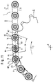
- FIG. 1 you can see two sprockets with the common axis of rotation a rear sprocket set of a bicycle, the larger sprocket with A and the smaller sprocket with C. is.
- the large sprocket A has 21 teeth and the small sprocket C 18 teeth.
- the chain B runs over the idler 10 a chain launcher device in the sprocket set A, C a.
- the normal chain circumferential direction corresponding to the forward drive is indicated by the arrow 11.
- At 12 you can see the upper running tangentially to the pedal crank sprocket set Chain center; at 15 is the entry of chain C into the rear sprocket set shown.
- Figure 1 represents the switching process of the smaller sprocket C on the larger sprocket A. You can see in the upper Half of Figure 1 that the chain B is still engaged with the smaller sprocket C. In the lower half of Figure 1 you can see that part of chain B is already on the larger one Sprocket A rests.
- the transition of the chain B from the small sprocket C to the large sprocket A is vertical by moving the idler 10 introduced to the drawing level to the opposite the time of the state according to FIG. 1 earlier time, to which the tooth A1 of the large sprocket A before Area of the stator 10 was.
- a transition zone is the Chain that emerged as a whole with T, the trailing one End marked with T1 and its leading end with T2 is. This transition zone moves as the sprocket set continues to rotate A, C in the direction of rotation 11 further.
- FIG. 2 which shows the transition region T enlarged, you can see a chain link point B1.
- This chain link point B1 is in the usual way by a bolt 13 and a chain roller 14 formed.
- the chain hinge point B1 is the chain hinge point that before the switching movement of the stator becomes effective 10 still fully engaged with the small sprocket C enters a tooth gap between teeth C1 and C2 of the small sprocket C.
- the chain pivot point B5 which is the same is designed like chain link point B1, is the first chain link point, which after the switching movement of the Stator 10 comes into full engagement with the large sprocket A. is in the tooth gap between the two teeth A4 and A5 of the large sprocket A.
- the large sprocket A has between the successive teeth A2 and A4 a missing tooth which is labeled A3.
- At this tooth defect A3 there is a spur, which is drawn in dashed lines at A3 is; this will be discussed later.
- the small sprocket C has between its teeth C2 and C4 also a tooth defect C3.
- the two defects A3 and C3 result in enlarged tooth gaps ZA and ZC.
- These tooth gaps ZA and ZC facilitate the transition of chain B from the small one Sprocket C on the large sprocket A. This can be seen from the Figure 3 see where the transition zone T and the tooth gaps ZC and ZA are also located.
- the chain B points between successive chain hinge points, for example the chain hinge points B1 and B2, an inner one Chain link pair D2i.
- the one on the left in FIG. 3 Chain link of a chain link pair is with the index g named; this is the chain link that becomes the bigger one Sprockets of a sprocket set is located while the chain link on the right with the index d is designated.
- the pair of link plates D2i consists of the link plates D2ig and D2id and the outer pair of link plates D3a from the two link plates D3ag and D3ad.
- Between further chain link points B3 and B6 then follow alternately one pair of inner link plates D4i, one pair of outer link plates D5a and another pair of inner link plates D6i etc.
- the chain roller 14 of the chain joint point B1 is still fully in Engagement with two successive teeth C1 and C2 of the small one Sprocket C.
- the chain roller 14 of the chain hinge point B2 is already somewhat excavated from the enlarged tooth gap ZC.
- the next chain link point B3 is not in driving engagement with tooth A2, rather the left link plate D3ag lies on the outside Pair of link plates D3a in FIG. 3 to the right of tooth A2, the radial height of the chain link point B3 thereby it is determined that the left link plate D3ag of the pair of link plates D3a rests on a ramp 16, which is a relief-like Indentation 17 in the viewer facing in FIG Figure 3 right front of the large sprocket A after limited radially inside.
- the chain link point B3 is therefore opposite the tooth A2 perpendicular to the drawing plane of Figure 2 and in Figure 3 shifted to the right and is out of engagement with the Tooth A2, as can be seen in particular from FIG. 3.
- the tooth A4 reaches between the two link plates of the outer pair of link plates D5a a.
- the chain link point B5 is the first link point, the one with its chain roller 14 between two successive ones Teeth A4 and A5 of the large sprocket A.
- the tooth A4 of the large sprocket A which at the transition of the Chain from the small sprocket C to the large sprocket A as first tooth between the link plates of a pair of link plates D5a or D5i occurs, is provided with a bevel 22 ( Figures 3, 5 and 6).
- the bevel 22 means a weakening of the A4 tooth. If regardless of the assignment of an inner Chain link pair or an outer chain link pair for Tooth gap ZA always the same tooth A4 according to FIGS. 3 and 5 be the first between the plates of the respective pair of link plates D5a or D5i occurs, this means that only one tooth, in the For example, the tooth A4, provided with the bevel 22 and thus must be weakened.
- the teeth A1, A2 and A5 are provided with bevels 27.
- At Initiation of the switching process from the small sprocket C to the large sprocket A becomes the idler 10 and accordingly the chain B pressed towards the large sprocket A and approximated. So that despite this approach, the chain does not get on the tooth tips the teeth of the large sprocket can open these bevels 27 are provided. If the chain B after the Entry into the chain wheel set as the chain wheel set continues to rotate radial with respect to the axis of the chain wheel set Moved inside, it does not hit the tips of the teeth, but rather the bevels 27 and then slides over the bevels 27 towards engagement with the small sprocket C.
- This tooth A4 has the Bevel 22 on its remote from the small sprocket Side on so that the A4 tooth is indifferent whether it is in radial alignment with the outer plates D5a according to FIG. 3 or with the inner plates D5i occurs according to Figure 5, thread between the respective tabs can.
- Figures 3 and 5 show that none of the chain transition teeth involved an explosive effect on a pair of link plates can exercise. This is especially true where Teeth in inner pairs of tabs, i.e. in narrow spaces between two inner tabs, intervene and where therefore according to the state of the Technology always the risk of the outer tabs breaking off the chain pin existed.
- FIG. 7 is the switching from the large sprocket A shown on the smaller sprocket C in detail.
- FIG. 6 7 and 8 are the bevels on the teeth A5 and A6 23 attached, for which reference was made in particular to FIG. 6 becomes.
- the teeth A5 and A6 are the teeth that oppose the normal direction of rotation 11 as the first tooth A5 and as the second Follow tooth A6 on the tooth A4 that was on the previous tooth considered switching from the small sprocket C to that large sprocket A as the first between the plates of a pair of plates intervened.
- the tooth A5 with the bevel 23 is the tooth that contrary to the direction of rotation 11, second to the fault A3 follows and the tooth A6 with the bevel 23 is the one who as the third tooth follows the defect A3.
- Switching from the large sprocket A to the small sprocket C is generally less critical than switching from the small sprocket C on the large sprocket A. This is due to The first reason is that it is easier to live under tension standing chain B from a large sprocket A to a small one Sprocket C implement what is supported by the chain tension becomes. Another reason is that the transition from one large sprocket to a small sprocket is then made if you shift in the direction from mountain gear to overdrive wants: then there is regularly a cheap one for switching greater circulation speed before and on the other hand also for switching cheap low torque.
- the bevels 23 now serve this purpose the teeth A5 and A6, with respect to the tooth A5 in particular is again referred to Figure 6.
- the bevels 23 are as can be seen in particular from FIG. 6 and from FIG. 8, lengthways a circumferential line TK ( Figure 6) opposite one to the axis of the Sprocket set orthogonal plane so inclined that as it progresses in the direction of rotation 11 along the circumferential line TK Sloping surface 23 increasing from the adjacent smaller sprocket C. has axial distance. This also results from the comparison the tooth thicknesses b and a in the area of the respective leading edge teeth A5 and A4, where b is less than a.
- hinge point B6 A radial inward movement of hinge point B6 is thereby preventing the tab D7ag lying on the left in FIG of the outer link plate pair D7a on the shoulder 30 (see Figure 6) supports, which arose as a result of the bevel 23 , on the other hand, the chain rollers 14 of the articulation points Lean B7 and B8 against teeth C7 and C8, respectively. Against that the hinge point B9 between the successive teeth C8 and Intervene C9.
- the existence of the extended tooth gap ZA favors together with the bevels 23 of the teeth A5 and A6 the Inclination of the chain when the idler wheel moves 10 in Direction to the smaller sprocket, as shown in Figure 8.
- the enlarged tooth gap ZC according to FIG. 7 can also be used for relief the chain transition between the large sprocket and the small sprocket C.
- Figure 9 shows the situation that when switching the Chain B from the large sprocket A to the small sprocket C in Area of the tooth defect A3 an outer pair of chain links D5a and accordingly in the area of tooth A4 an inner pair of link plates D6i and in the area of tooth A5 an outer pair of link plates D7a lies. Then at the entry point 15 according to FIG. 1 the chain due to its limited flexibility Main plane should not be bent out to such an extent that the Left link D7ag of the outer pair of link plates D7a to the right of tooth A5 comes to rest; rather, the left tab D7ag of the outer link plate pair D7a according to FIG. 9 still on the pass the left side of tooth A5.
- tooth A6 left plate D8ig of the inner link plate pair D8i can then pass the right side of tooth A6 in FIG. 9.
- the bevel 23 of tooth A6 favors the transition the chain from the large sprocket A to the small sprocket C.
- the chain is therefore more likely to open change the small sprocket C if it has been adjusted once or biasing the stator 10 toward the smaller sprocket C in the inlet area 15 of the tooth A5 or A6 is present.
- Figure 1 shows that there is a large sprocket A overall three enlarged tooth gaps ZA and two on the small sprocket C. enlarged tooth gaps ZC there.
- the arrangement recognizes one in Figure 10 based on the entire circumference of the sprocket set.
- An irregular polygon line can be seen in FIG. 10 P, within which elongated polygon sides P1 with shorter ones Alternate polygon sides P2.
- the longer polygon sides P1 correspond to a central angle ⁇ and extend from the hinge point B5 to hinge point B3.
- the polygon side corresponds to P1 the connecting line V according to FIG. 11.
- the shorter one Polygon side P2 corresponds, for example, to the connection between the hinge point B2 and the hinge point B3.
- the teeth A2, A4, A5 and the tooth defect A3 are also indicated schematically in FIG. 10.
- the design of a sprocket according to Figure 10 requires Considerable effort in that the tooth and tooth gap distribution over the circumference according to the polygon line P each time must be calculated separately.
- the angle setting between the sprockets of each pair of sprockets once and for all be set so that when switching from the small to the large sprocket the chain length of the curved or kinked extending chain section B1-B5 between the articulation points B1 and B5 each at least approximately that of the one prevailing there Tooth geometry predetermined path of this chain section between hinge points B1 and B5.
- tooth number differences of more than 3 can also be more than the above Hinge points B1-B5 fall into the transition area.
- spur has no tooth function; it only serves to guide the chain at the side Moving the chain backwards against the normal direction of rotation 11.
- the spur is usually, if at all, only in the enlarged tooth gaps of the largest sprocket or the largest sprockets of a sprocket set provided.
Landscapes
- Engineering & Computer Science (AREA)
- Chemical & Material Sciences (AREA)
- Combustion & Propulsion (AREA)
- Transportation (AREA)
- Mechanical Engineering (AREA)
- Gears, Cams (AREA)
- Transmissions By Endless Flexible Members (AREA)
Description
wobei mindestens eine der Kettenradeinheiten als Mehrkettenradeinheit mit mindestens zwei Kettenrädern, nämlich einem größeren und einem kleineren Kettenrad, ausgebildet ist,
wobei weiter die beiden Kettenräder der Mehrkettenradeinheit je eine Vielzahl von Zähnen und eine entsprechende Vielzahl von zwischen jeweils einem Zahnpaar gebildeten Zahnlücken aufweist,
wobei weiter im allgemeinen die Zahnlücken als Einfachzahnlücken zur Aufnahme jeweils eines Kettengelenks ausgebildet sind,
wobei weiter die Kette von aufeinanderfolgenden Kettengelenken und von inneren und äußeren Laschenpaaren in abwechselnder Reihenfolge zwischen den Kettengelenken gebildet ist,
wobei weiter zum Umlegen der Kette zwischen den beiden Kettenrädern der Mehrkettenradeinheit eine Umlegeeinrichtung in einem Einlaufbereich vorgesehen ist, in welchem die Kette bei normaler Umlaufrichtung der Kette und der Kettenräder in die Mehrkettenradeinheit einläuft und diese Umlegeeinrichtung dazu ausgebildet ist, um der Kette Bewegungen in einer zur Achse der Mehrkettenradeinheit parallelen Richtung zu erteilen,
wobei weiter beim Umlegen der Kette zwischen den Kettenrädern der Mehrkettenradeinheit sich eine Kettenübergangsstrecke zwischen einem altbesetzten und einem neubesetzten der beiden Kettenräder ausbildet, welche Kettenübergangsstrecke den Umlaufbereich der Mehrkettenradeinheit vom Ketteneinlaufbereich bis zu einem Kettenablaufbereich der Mehrkettenradeinheit durchläuft,
wobei weiter die Kettenübergangsstrecke sich entgegen der normalen Umlaufrichtung der Mehrkettenradeinheit erstreckt von einem Kettengelenk, das als letztes Kettengelenk zwischen zwei Letztzähne eines Letztzähnepaars des altbesetzten Kettenrads eingreift, zu einem Kettengelenk, das als erstes zwischen zwei Erstzähne eines Erstzähnepaars des neubesetzten Kettenrads eingreift
und wobei in mindestens einem der Kettenumlegung in der Umlegerichtung vom kleineren Kettenrad zum größeren Kettenrad entsprechenden Kettenübergangumfangsbereich der Mehrkettenradeinheit an den Kettenrädern Gestaltungsmaßnahmen getroffen sind, um in diesem Kettenübergangumfangsbereich das Umlegen der Kette zwischen den beiden Kettenrädern zumindest in der Umlegerichtung vom kleineren Kettenrad zum größeren Kettenrad zu erleichtern und den Verlauf der entsprechenden Kettenübergangsstrecke festzulegen.
- Figur 1
- eine Seitenansicht eines Hinterradnabenkettenradsatzes eines Fahrrads mit Kette und Kettenwerfereinrichtung;
- Figur 2
- einen Ausschnitt aus Figur 1 in vergrößerter Darstellung beim Übergang der Kette von einem kleineren Kettenrad auf ein größeres Kettenrad;
- Figur 3
- eine Ansicht auf den in Figur 2 dargestellten Kettenübergangsbereich von radial außen;
- Figur 4
- eine Ansicht entsprechend Figur 2, jedoch bei anderer Zuordnung der inneren und äußeren Kettenlaschenpaare zu den Kettenrädern;
- Figur 5
- eine Ansicht von radial außen auf die Kettenübergangsstrecke gemäß Figur 4;
- Figur 6
- ein Detail des größeren Kettenrads gemäß Figuren 1-5;
- Figur 7
- eine Seitenansicht eines Kettenradsatzes mit einer Kettenübergangsstrecke, die sich beim Schalten von dem größeren Kettenrad auf das kleinere Kettenrad ausbildet;
- Figur 8
- eine Ansicht in Pfeilrichtung VIII der Figur 7;
- Figur 9
- eine Ansicht entsprechend Figur 8, jedoch bei Veränderung der Zuordnung äußerer und innerer Kettenglieder zu den Kettenrädern;
- Figur 10
- das Schema der Zahn- und Zahnlückenverteilung eines Kettenrads, etwa des größeren Kettenrads der Figur 1, und
- Figur 11
- den Ablauf der Kette von dem Kettenrad gemäß Figur 10.
Claims (17)
- Kettenschaltung, insbesondere für Fahrräder, umfassend eine treibende Kettenradeinheit und eine angetriebene Kettenradeinheit (A-C) sowie eine diese beiden Kettenradeinheiten miteinander verbindende Kette (B),
wobei mindestens eine (A-C) der Kettenradeinheiten als Mehrkettenradeinheit (A-C) mit mindestens zwei Kettenrädern (A,C), nämlich einem größeren (A) und einem kleineren Kettenrad (C), ausgebildet ist,
wobei weiter die beiden Kettenräder (A,C) der Mohrkettenradeinheit (A-C) je eine Vielzahl von Zähnen (A1...;C1...) und eine entsprechende Vielzahl von zwischen jeweils einem Zahnpaar (A1,A2;C1,C2) gebildeten Zahnlücken (A1-A2;C1-C2) aufweist,
wobei weiter im allgemeinen die Zahnlücken (A1-A2;C1-C2) als Einfachzahnlücken zur Aufnahme jeweils eines Kettengelenks ausgebildet sind,
wobei weiter die Kette (B) von aufeinanderfolgenden Kettengelenken (B1...) und von inneren (D2i) und äußeren Laschenpaaren (D3a) in abwechselnder Reihenfolge zwischen den Kettengelenken (B1...) gebildet ist,
wobei weiter zum Umlegen der Kette zwischen den beiden Kettenrädern (A,C) der Mehrkettenradeinheit (A-C) eine Umlegeeinrichtung (10) in einem Einlaufbereich (15) vorgesehen ist, in welchem die Kette (B) bei normaler Umlaufrichtung (11) der Kette (B) und der Kettenräder (A,C) in die Mehrkettenradeinheit (A-C) einläuft und diese Umlegeeinrichtung (10) dazu ausgebildet ist, um der Kette (B) Bewegungen in einer zur Achse (X) der Mehrkettenradeinheit (A-C) parallelen Richtung zu erteilen,
wobei weiter beim Umlegen der Kette (B) zwischen cen Kettenrädern (A,C) der Mehrkettenradeinheit (A-C) sich eine Kettenübergangsstrecke (B1-B5) zwischen einem altbesetzten (C) und einem neubesetzten (A) der beiden Kettenräder ausbildet, welche Kettenübergangsstrecke (B1-B5) den Umlaufbereich der Mehrkettenradeinheit (A-C) vom Ketteneinlaufbereich (15) bis zu einem Kettenablaufbereich (L) der Mehrkettenradeinheit (A-C) durchläuft,
wobei weiter die Kettenübergangsstrecke (B1-B5) sich entgegen der normalen Umlaufrichtung (11) der Mehrkettenradeinheit (A,C) erstreckt von einem Kettengelenk (B1), das als letztes Kettengelenk (B1) zwischen zwei Letztzähne (C1,C2) eines Letztzähnepaars (C1,C2) des altbesetzten Kettenrads (C) eingreift, zu einem Kettengelenk (B5), das als erstes zwischen zwei Erstzähne (A4,A5) eines Erstzähnepaars (A4,A5) des neubesetzten Kettenrads (A) eingreift
und wobei in mindestens einem der Kettenumlegung in der Umlegerichtung vom kleineren Kettenrad (C) zum größeren Kettenrad (A) entsprechenden Kettenübergangumfangsbereich (T) der Mehrkettenradeinheit (A-C) an den Kettenrädern (A,C) Gestaltungsmaßnahmen getroffen sind, um in diesem Kettenübergangumfangsbereich (T) das Umlegen der Kette (B) zwischen den beiden Kettenrädern (A,C) zumindest in der Umlegerichtung vom kleineren Kettenrad (C) zum größeren Kettenrad (A) zu erleichtern und den Verlauf der entsprechenden Kettenübergangsstrecke (B1-B5) festzulegen,
gekennzeichnet durch die folgenden Merkmale:a) in dem dem Umlegen von dem kleineren Kettenrad (C) auf das größere Kettenrad (A) entsprechenden Kettenübergangumfangsbereich (T) ist an dem größeren Kettenrad (A) unter Bildung einer zwischen Einfachzahnlücken angeordneten Doppelzahnlücke (ZA) ein Zahn (bei A3) ausgespart, welcher in der normalen Umlaufrichtung (11) dem vorlaufenden Erstzahn (A4) des Erstzähnepaars (A4,A5) des größeren Kettenrads (A) vorangeht;b) an dem großen Kettenrad (A) ist auf seiner dem kleineren Kettenrad (C) zugekehrten Seitenfläche im Basisbereich eines Zahns (A2), welcher der Doppelzahnlücke (ZA) in der normalen Umlaufrichtung (11) vorausgeht und gewünschtenfalls noch in dem vorlaufenden Endbereich der Doppelzahnlücke (ZA) eine Laschenauflagerampe (16) ausgebildet, welche in normaler Umlaufrichtung (11) dem nachlaufenden Letztzahn (C2) des Letztzähnepaars (C1, C2) des kleineren Kettenrads (C) nachläuft;c) durch die Laschenauflagerampe (16) und einen Boden (ZA1) der Doppelzahnlücke (ZA) ist ein - in axialer Richtung betrachtet - nach radial außen konvex gekrümmter oder geknickter Verlauf (B1,B2,B3,B4,B5) der Kettenübergangsstrecke (B1-B5) innerhalb des Kettenübergangumfangsbereichs (T) zwischen dem Erstzähnepaar (A4,A5) des größeren Kettenrads (A) und dem Letztzähnepaar (C1,C2) des kleineren Kettenrads (C) erzwungen, wobei die gekrümmte Kettenübergangsstrecke (B1-B5) in die Zahnlücke (C1-C2) zwischen den beiden Letztzähnen (C1,C2) des Letztzähnepaars (C1,C2) des kleineren Kettenrads (C) einmündet;d) der in normaler Umlaufrichtung (11) vorauslaufende Erstzahn (A4) des Erstzähnepaars (A4,A5) des größeren Kettenrads (A) ist für den Eingriff sowohl zwischen die Laschen eines Innenlaschenpaars (D5i) als auch zwischen die Laschen eines Außenlaschenpaars (D5a) ausgebildet. - Kettenschaltung nach Anspruch 1,
dadurch gekennzeichnet,
daß an dem kleineren Kettenrad (C) ein auf den nachlaufenden Letztzahn (C2) des Letztzähnepaars (C1,C2) folgender Zahn (bei C3) unter Bildung einer Mehrfachzahnlücke (ZC) des kleineren Kettenrads (C) ausgespart ist. - Kettenschaltung nach einem der Ansprüche 1 und 2,
dadurch gekennzeichnet,
daß die Laschenauflagerampe (16) von dem radial inneren Rand einer reliefartigen Vertiefung (17) in einer dem kleineren Kettenrad (C) zugekehrten Seitenfläche des größeren Kettenrads (A) gebildet ist. - Kettenschaltung nach Anspruch 3,
dadurch gekennzeichnet,
daß die reliefartige Vertiefung (17) eine in normaler Umlaufrichtung (11) vorauslaufende in bezug auf die Achse (X) der Mehrkettenradeinheit (A-C) im wesentlichen radial verlaufende Vorlaufkante (17a) besitzt, wobei eine dieser Vorlaufkante (17a) in axialer Richtung benachbarte Kettenlasche (D2ig) jeweils über diese Vorlaufkante (17a) hinwegläuft. - Kettenschaltung nach Anspruch 4,
dadurch gekennzeichnet,
daß die reliefartige Vertiefung (17) in einem der normalen Umlaufrichtung (11) entsprechenden Vorlaufbereich vor einem Vorlaufende der Laschenauflagerampe (16) radial einwärts in Richtung auf die Achse (X) der Mehrkettenradeinheit (A-C) erweitert ist. - Kettenschaltung nach einem der Ansprüche 1-5,
dadurch gekennzeichnet,
daß der vorlaufende Erstzahn (A4) des Erstzähnepaars (A4,A5) des größeren Kettenrads (A) auf seiner von dem kleineren Kettenrad (C) abgelegenen Seitenfläche (22) nach radial auswärts und zum kleineren Kettenrad (C) hin abgeschrägt ist. - Kettenschaltung nach einem der Ansprüche 1-6,
dadurch gekennzeichnet,
daß zumindest ein Teil derjenigen Zähne (A1,A2,A5,A6) des größeren Kettenrads (A), aie nicht identisch sind mit dem vorlaufenden Erstzahn (A4) des Erstzähnepaars (A4,A5) des größeren Kettenrads (A) auf ihrer dem kleineren Kettenrad (C) zugekehrten Seite (27) nach radial außen und von dem kleineren Kettenrad (C) weg abgeschrägt sind, und zwar mindestens und vorzugsweise in einem radial äußeren Bereich (27) ihrer radialen Höhe. - Kettenschaltung nach einem dem Ansprüche 1-7,
dadurch gekennzeichnet,
daß an der Stelle (A3) des ausgesparten Zahns der Doppelzahnlücke (ZA) zumindest des größeren Kettenrads (A) ein Sporn (19) vorgesehen ist, welcher im Fall der axialen Nachbarschaft zu einem Innenlaschenpaar (D4i) außerhalb des Zwischenraums dieses Innenlaschenpaars (D4i) liegt, und zwar auf der Außenseite derjenigen Innenlasche (D4ig), welche dem kleineren Kettenrad (C) ferner ist, und welcher im Fall der axialen Nachbarschaft zu einem Außenlaschenpaar (D4a) in den Zwischenraum der Laschen dieses Außenlaschenpaars (D4a) hineinragt. - Kettenschaltung nach einem der Ansprüche 1 bis 8,
dadurch gekennzeichnet,
daß zur Erleichterung des Kettenumlegens in der Umlegerichtung vom größeren Kettenrad (A) zum kleineren Kettenrad (C) zusätzliche Gestaltungsmaßnahmen in dem für die Übergangsrichtung vom kleineren Kettenrad (C) zum größeren Kettenrad (A) ausgestalteten Kettenübergangumfangsbereich an Zähnen (A1,A2,A4,A5,A6) des größeren Kettenrads (A) vorgesehen sind. - Kettenschaltung nach Anspruch 9,
dadurch gekennzeichnet,
daß der nachlaufende Erstzahn (A5) des Erstzähnepaars (A4, A5) des größeren Kettenrads (A) oder/und der diesem nachlaufenden Erstzahn (A5) in normaler Umlaufrichtung (11) folgende Zahn (A6) des größeren Kettenrads (A) Abschrägungen (23) auf der jeweiligen dem Kleineren Kettenrad (C) zugekehrten Seite besitzen, und zwar so, daß die abgeschrägten Flächen (23) - bei einer Betrachtung in radialer Richtung von radial außen - im Sinne der normalen Umlaufrichtung (11) nach vorn und vom kleineren Kettenrad (C) weg verlaufen. - Kettenschaltung nach Anspruch 10,
dadurch gekennzeichnet,
daß beide Zähne, d.h. also sowohl der nachlaufende Erstzahn (A5) des größeren Kettenrads (A) als auch der diesem in normaler Umlaufrichtung 11 nachfolgende Zahn (A6) Abschrägungen (23) besitzen, wobei eine der Kettenumlegerichtung vom größeren Kettenrad (A) zum kleineren Kettenrad (C) entsprechende Kettenübergangsstrecke (B5-B9) bei axialer Nachbarschaft eines ihr zugehörigen Innenlaschenpaars (D6i) zu dem nachlaufenden Erstzahn (A5) des größeren Kettenrads (A) mit der Außenseite ihrer dem kleineren Kettenrad (C) fernen Innenlasche (D6ig) an der Abschrägung (23) des nachlaufenden Erstzahns (A5) des Erstzähnepaars (A4,A5) des größeren Kettenrads (A) anliegt, während im Falle der axialen Nachbarschaft eines Außenlaschenpaars (D7a) der Kettenübergangsstrecke (B5-B9) zum nachlaufenden Erstzahn (A5) des Erstzähnepaars (A4,A5) des größeren Kettenrads (A) dieser Erstzahn (A5) zwischen die Außenlaschen dieses Außenlaschenpaars (D7a) eingreift und dann eine dem kleineren Kettenrad (C) ferne Innenlasche (D8ig) eines dem zuvor genannten Außenlaschenpaar (D7a) nachfolgenden Innenlaschenpaars (D8i) an der Abschrägung (23) des auf den nachlaufenden Erstzahn (A5) des Erstzähnepaars (A4,A5) des größeren Kettenrads (A) nachfolgenden Zahns (A6) des größeren Kettenrads (A) anliegt. - Kettenschaltung nach einem der Ansprüche 1-11,
dadurch gekennzeichnet,
daß der erste (A2) und ggf. auch der zweite (A1) der der vergrößerten Zahnlücke des größeren Kettenrads (A) vorauslaufenden Zähne (A1,A2) im Sinne einer Anpassung an eine dort bereits einsetzende Schrägstellung der Kette (B) gegenüber ihrer Umlaufebene schräggestellt, axial versetzt oder nach radial außen abgeschrägt ist. - Kettenschaltung nach einem der Ansprüche 1-12,
dadurch gekennzeichnet,
daß die beiden Kettenräder, d.h. das größere Kettenrad (A) und das kleinere Kettenrad (C), Teil einer größeren Gruppe von Kettenrädern der Mehrkettenradeinheit (A-C) sind, wobei dann entweder das bisher als größeres Kettenrad betrachtete Kettenrad (A) das kleinere Kettenrad in bezug auf ein ihm benachbartes noch größeres Kettenrad ist und/oder das bisher als das kleinere Kettenrad betrachtete Kettenrad (C) das größere Kettenrad in bezug auf ein noch kleineres Kettenrad ist und wobei die in den vorstehenden Ansprüchen 1-12 angegebenen Beziehungen für mindestens einen Teil der jeweils zusammen ein Kettenradpaar bildenden benachbarten Kettenräder gelten. - Kettenschaltung nach einem der Ansprüche 1-13,
dadurch gekennzeichnet,
daß ein Sporn (19) jeweils nur im Bereich der Doppelzahnlücke des größten Kettenrads (A) oder der größten Kettenräder einer Mehrkettenradeinheit vorgesehen ist. - Kettenschaltung nach einem der Ansprüche 1-14,
dadurch gekennzeichnet,
daß einem Kettenradpaar (A,C) einer Mehrkettenradeinheit (A-C) eine Mehrzahl von über den Umfang verteilton Kettenübergangumfangsbereiche (T) zugeordnet sind. - Kettenschaltung, insbesondere für Fahrräder, umfassend eine treibende Kettenradeinheit und eine angetriebene Kettenradeinheit (A-C) sowie eine diese beiden Kettenradeinherten miteinander verbindende Kette (B),
wobei mindestens eine (A-C) der Kettenradeinheiten als Mehrkettenradeinheit (A-C) mit mindestens zwei Kettenrädern (A-C), nämlich einem größeren (A) und einem kleineren Kettenrad (C), ausgebildet ist,
wobei weiter die beiden Kettenräder (A,C) der Mehrkettenradeinheit (A-C) je eine Vielzahl von Zähnen (A1...;C1...) und eine entsprechende Vielzahl von zwischen jeweils einen Zahnpaar (A1,A2;C1,C2) gebildeten Zahnlücken (A1-A2;C1-C2) aufweist,
wobei weiter die Kette (B) von aufeinanderfolgenden Kettengelenken (B1...) und von inneren (D2i) und äußeren Laschenpaaren (D3a) in abwechselnder Reihenfolge zwischen den Kettengelenken (B1...) gebildet ist,
wobei weiter zum Umlegen der Kette zwischen den beiden Kettenrädern (A,C) der Mehrkettenradeinheit (A-C) eine Umlegeeinrichtung (10) in einem Einlaufbereich (15) vorgesehen ist, in welchem die Kette (B) bei normaler Umlaufrichtung (11) der Kette (B) und der Kettenräder (A,C) in die Mehrkettenradeinheit (A-C) einläuft und diese Umlegeeinrichtung (10) dazu ausgebildet ist, um der Kette (B) Bewegungen in einer zur Achse (X) der Mehrkettenradeinheit (A-C) parallelen Richtung zu erteilen,
wobei weiter beim Umlegen der Kette (B) zwischen den Kettenrädern (A,C) der Mehrkettenradeinheit (A-C) sich eine Kettenübergangsstrecke (B1-B5) zwischen einem altbesetzten (C) und einem neubesetzten (A) der beiden Kettenräder ausbildet, welche Kettenübergangsstrecke (B1-B5) den Umlaufbereich der Mehrkettenradeinheit (A-C) vom Ketteneinlaufbereich (15) bis zu einem Kettenablaufbereich (L) der Mehrkettenradeinheit (A-C) durchläuft,
wobei weiter die Kettenübergangsstrecke (B1-B5) sich entgegen der normalen Umlaufrichtung (11) der Mehrkettenradeinheit (A,C) erstreckt von einem Kettengelenk (B1), das als letztes Kettengelenk (B1) zwischen zwei Letztzähne (C1,C2) eines Letztzähnepaars (C1,C2) des altbesetzten Kettenrads (C) eingreift, zu einem Kettengelenk (B5), das als erstes zwischen zwei Erstzähne (A4,A5) eines Erstzähnepaars (A4,A5) des neubesetzten Kettenrads (A) eingreift
und wobei in mindestens einem der Kettenumlegung in der Umlegerichtung vom kleineren Kettenrad (C) zum größeren Kettenrad (A) entsprechenden Kettenübergangumfangsbereich (T) der Mehrkettenradeinheit (A-C) an den Kettenrädern (A,C) Gestaltungsmaßnahmen getroffen sind, um in diesem Kettenübergangumfangsbereich (T) das Umlegen der Kette (B) zwischen den beiden Kettenrädern (A,C) zumindest in der Umlegerichtung vom kleineren Kettenrad (C) zum größeren Kettenrad (A) zu erleichtern und den Verlauf der entsprechenden Kettenübergangsstrecke (B1-B5) festzulegen,
dadurch gekennzeichnet,
daß bei Aussparung mindestens eines Zahns (bei A3) zwischen zwei aufeinanderfolgenden Zähnen (A2,A4) eines Kettenrads (A) und dadurch veranlaßter Bildung einer Mehrfachzahnlücke, insbesondere Doppelzahnlücke (ZA) die Zahnlückenkontur dieser Mehrfachzahnlücke (ZA) und die Zahnlückenkontur einer auf diese Mehrfachzahnlücke (ZA) unmittelbar nachfolgenden weiteren Zahnlücke (A4-A5) derart aufeinander abgestimmt sind, daß bei Einliegen einer entsprechenden Zahl von Kettengelenken (B3-B5) in diesen Zahnlücken (ZA,A4-A5) deren Gelenkachsen auf einer gemeinsamen Verbindungsgeraden (V) liegen, wobei das in der Mehrfachzahnlücke (ZA) vorlaufende Kettengelenk (B3) und das in der nachfolgenden Zahnlücke (A4,A5) aufgenommene Kettengelenk (B5) mindestens beim Auslauf ins Zugtrum gemeinsam an der Nachlaufflanke des ihnen jeweils vorauslaufenden Zahns (A2 bzw.A4) anteilmäßig drehmomentübertragend anliegen. - Kettenschaltung nach Anspruch 16,
dadurch gekennzeichnet,
daß die Mittelpunkte der Zahnlücken des Kettenrads ein unregelmäßiges Polygon bilden, wobei die jeweils auf einer gemeinsamen Verbindungslinie (V) liegenden Gelenkachsen jeweils größere Polygonseiten (G-G-G) bilden.
Applications Claiming Priority (2)
| Application Number | Priority Date | Filing Date | Title |
|---|---|---|---|
| DE4330989 | 1993-09-13 | ||
| DE4330989A DE4330989A1 (de) | 1993-09-13 | 1993-09-13 | Kettenschaltung, insbesondere für Fahrräder |
Publications (2)
| Publication Number | Publication Date |
|---|---|
| EP0642972A1 EP0642972A1 (de) | 1995-03-15 |
| EP0642972B1 true EP0642972B1 (de) | 1998-08-05 |
Family
ID=6497560
Family Applications (1)
| Application Number | Title | Priority Date | Filing Date |
|---|---|---|---|
| EP94109457A Expired - Lifetime EP0642972B1 (de) | 1993-09-13 | 1994-06-18 | Kettenschaltung, insbesondere für Fahrräder |
Country Status (4)
| Country | Link |
|---|---|
| US (1) | US5503598A (de) |
| EP (1) | EP0642972B1 (de) |
| CN (1) | CN1054818C (de) |
| DE (2) | DE4330989A1 (de) |
Cited By (6)
| Publication number | Priority date | Publication date | Assignee | Title |
|---|---|---|---|---|
| EP2039602A1 (de) | 2007-09-21 | 2009-03-25 | SRAM Deutschland GmbH | Mehrfachkettenradeinheit für Fahrräder |
| US7846048B2 (en) | 2006-03-07 | 2010-12-07 | Sram Deutschland Gmbh | Multi-speed sprocket assembly |
| US8834309B2 (en) | 2008-07-03 | 2014-09-16 | Sram Deutschland Gmbh | Multiple sprocket assembly |
| US9964196B2 (en) | 2014-05-20 | 2018-05-08 | Shimano Inc. | Bicycle sprocket |
| DE102008064957B4 (de) * | 2008-07-03 | 2025-09-25 | Sram Deutschland Gmbh | Mehrfach-Kettenzahnrad für ein Fahrrad |
| DE102017005440B4 (de) | 2016-06-24 | 2026-03-19 | Shimano Inc. | Fahrradritzel und Fahrradritzelanordnung |
Families Citing this family (61)
| Publication number | Priority date | Publication date | Assignee | Title |
|---|---|---|---|---|
| US5716297A (en) * | 1993-09-13 | 1998-02-10 | Fichtel & Sachs Ag | Derailleur arrangement for bicycles |
| DE4434752A1 (de) * | 1994-09-29 | 1996-04-04 | Fichtel & Sachs Ag | Kettenschaltung, insbesondere für Fahrräder |
| US5666859A (en) * | 1994-12-02 | 1997-09-16 | Fichtel & Sachs Ag | Latching shifter for a bicycle transmission |
| DE4445035C1 (de) * | 1994-12-16 | 1996-06-05 | Fichtel & Sachs Ag | Kettenschaltung |
| US5876295A (en) * | 1996-01-23 | 1999-03-02 | Cloyes Gear And Products, Inc. | Roller chain drive system having improved noise characteristics |
| FR2744418B1 (fr) * | 1996-02-02 | 1998-04-24 | Thierry Joel | Pedalier a changement automatique de plateaux |
| DE19606667C2 (de) * | 1996-02-23 | 1999-10-14 | Sram De Gmbh | Kettenschaltung für Fahrräder |
| US5921140A (en) * | 1996-04-04 | 1999-07-13 | Fichtel & Sachs Ag | Index shifter for a bicycle transmission and a method of making an index shifter for a bicycle transmission |
| US5921878A (en) * | 1996-07-03 | 1999-07-13 | Cloyes Gear And Products, Inc. | Roller chain drive system having improved noise characteristics |
| US5921879A (en) * | 1996-07-25 | 1999-07-13 | Cloyes Gear And Products, Inc. | Random engagement roller chain sprocket with staged meshing and flank relief to provide improved noise characteristics |
| US6090003A (en) * | 1996-07-25 | 2000-07-18 | Cloyes Gear & Products, Inc. | Random engagement roller chain sprocket having improved noise characteristics |
| BR9710575A (pt) * | 1996-07-25 | 1999-09-14 | Cloyes Gear & Products Inc | Roda dentada de corrente de rolos, de engate aleatório, com caracterìsticas de ruìdo aperfeiçoadas. |
| US6761657B2 (en) | 1996-12-19 | 2004-07-13 | Cloyes Gear And Products, Inc. | Roller chain sprocket with added chordal pitch reduction |
| US7416500B2 (en) * | 1996-12-19 | 2008-08-26 | Cloyes Gear And Products, Inc. | Random engagement roller chain sprocket and timing chain system including same |
| TW331290U (en) * | 1997-08-01 | 1998-05-01 | Tracer Company Ltd | Improved structure of a chain wheel assembly of a bicycle |
| US6045472A (en) * | 1997-12-30 | 2000-04-04 | National Science Council | Integrated up-and downshifting configuration of a multistage sprocket assembly for a bicycle |
| US6013001A (en) * | 1998-02-04 | 2000-01-11 | Shimano, Inc. | Bicycle sprocket having recesses beneath chain receiving edges |
| US6293884B1 (en) * | 1999-09-08 | 2001-09-25 | Chattin Cluster Gears, Inc. | Cluster sprockets for bicycle transmissions and other prime movers |
| US6340338B1 (en) * | 2000-09-13 | 2002-01-22 | Shimano Inc. | Bicycle sprocket |
| EP1354792A1 (de) * | 2002-04-18 | 2003-10-22 | Campagnolo S.R.L. | Kettenblatt-Anordnung für Fahrradschaltung |
| EP1359087A1 (de) * | 2002-04-30 | 2003-11-05 | Campagnolo S.R.L. | Zahnrad für eine Fahrradkettenschaltung |
| US6923741B2 (en) † | 2002-08-30 | 2005-08-02 | Shimano Inc. | Top sprocket for a rear sprocket assembly and rear sprocket assembly for a bicycle |
| DE10256746A1 (de) * | 2002-12-05 | 2004-06-24 | Hans Helmig Gmbh | Schaltungskettenräder |
| DE10347784B4 (de) * | 2003-10-10 | 2017-04-06 | Sram Deutschland Gmbh | Geräuscharme Kettenschaltung |
| US8096908B2 (en) * | 2004-12-14 | 2012-01-17 | Shimano, Inc. | Bicycle sprocket with a laterally projecting gear change tooth |
| US8226511B2 (en) * | 2005-01-08 | 2012-07-24 | Shimano, Inc. | Bicycle sprocket tooth with a shift assist radius greater than a reference tooth radius |
| US8617015B2 (en) * | 2005-09-27 | 2013-12-31 | Wick Werks, LLC | Bicycle chain rings |
| US20090069135A1 (en) * | 2007-09-12 | 2009-03-12 | Douglas Chiang | Sprocket of bicycle with special designed tooth |
| US8235850B2 (en) * | 2008-12-01 | 2012-08-07 | Tien Hsin Industries Co., Ltd. | Multiple sprocket assembly |
| DE102008060501B4 (de) * | 2008-12-04 | 2015-10-15 | Tien Hsin Industries Co., Ltd. | Mehrfachzahnkranzanordnung |
| US9376165B2 (en) * | 2009-10-16 | 2016-06-28 | Shimano Inc. | Bicycle sprocket |
| DE102011013695B4 (de) * | 2011-03-11 | 2024-02-01 | Sram Deutschland Gmbh | Antriebseinheit am Hinterrad eines Fahrrades |
| CN103587643A (zh) * | 2012-11-21 | 2014-02-19 | 宁波力盟工业有限公司 | 变速齿轮和具有变速齿轮的自行车 |
| DE102013220293A1 (de) | 2013-10-08 | 2015-04-09 | Robert Bosch Gmbh | Motorisch und mit Muskelkraft betreibbares Fahrzeug mit Gangwechsel-Unterstützung |
| US9581229B2 (en) | 2014-02-10 | 2017-02-28 | Wolf Tooth Components, LLC | Sprocket |
| US9394986B2 (en) | 2014-02-10 | 2016-07-19 | Wolf Tooth Components, LLC | Sprocket |
| US9581230B2 (en) | 2014-02-10 | 2017-02-28 | Wolf Tooth Components, LLC | Sprocket |
| US9394987B2 (en) | 2014-02-10 | 2016-07-19 | Wolf Tooth Components, LLC | Sprocket |
| WO2015131023A1 (en) * | 2014-02-27 | 2015-09-03 | Eko Sport, Inc. | Alternating tooth chain ring |
| US9625027B2 (en) | 2014-04-08 | 2017-04-18 | Wolf Tooth Components, LLC | Sprocket |
| US9404565B2 (en) | 2014-04-08 | 2016-08-02 | Wolf Tooth Components, LLC | Sprocket |
| US9581231B2 (en) | 2014-04-08 | 2017-02-28 | Wolf Tooth Components, LLC | Sprocket |
| US9463844B2 (en) | 2014-09-01 | 2016-10-11 | Shimano Inc. | Bicycle sprocket and bicycle sprocket assembly |
| DE102015219522B4 (de) | 2014-10-14 | 2025-07-24 | Sram Deutschland Gmbh | Mehrfach-Kettenradanordnung für eine Hinterradnabe |
| US20160208903A1 (en) * | 2015-03-25 | 2016-07-21 | Wick Werks, LLC | Chainrings with Alternating Tooth Thickness Offset |
| WO2016168078A1 (en) | 2015-04-13 | 2016-10-20 | Eko Sport, Inc. | Chain ring with teeth oppositely laterally engaging a drive chain |
| DE102016009814A1 (de) | 2015-09-09 | 2017-03-09 | Sram Deutschland Gmbh | Rollenketten-Innenlasche |
| EP3141776B1 (de) | 2015-09-09 | 2023-08-23 | SRAM Deutschland GmbH | Rollenketten-innenlasche |
| US20170101159A1 (en) * | 2015-10-09 | 2017-04-13 | Shimano Inc. | Bicycle sprocket and bicycle sprocket assembly |
| DE102015016767B4 (de) * | 2015-12-23 | 2025-11-13 | Sram Deutschland Gmbh | Antriebsanordnung eines Fahrrades mit einer Mehrfach-Kettenradanordnung |
| US9885409B1 (en) * | 2016-09-12 | 2018-02-06 | Shimano Inc. | Bicycle sprocket and bicycle rear sprocket assembly |
| US10507888B2 (en) * | 2016-11-10 | 2019-12-17 | Shimano Inc. | Bicycle crank assembly and bicycle sprocket assembly |
| US10577050B2 (en) * | 2016-12-26 | 2020-03-03 | Shimano Inc. | Bicycle sprocket |
| US10577051B2 (en) * | 2017-09-15 | 2020-03-03 | Shimano Inc. | Bicycle sprocket |
| EP3831703B1 (de) * | 2018-02-28 | 2023-01-25 | SRAM Deutschland GmbH | Hinterrad-ritzelanordnung mit zwei einstückigen zur gemeinsamen drehung miteinander verbundenen teilanordnungen |
| TWI821507B (zh) | 2019-01-29 | 2023-11-11 | 義大利商坎帕克諾羅公司 | 具有增大躍變的後變速盤 |
| CN112057266B (zh) * | 2019-05-27 | 2021-07-13 | 南京久运科技有限公司 | 护理床垫骨架及具有起坐、翻身功能的医疗护理床垫 |
| DE202019003258U1 (de) | 2019-08-05 | 2019-09-02 | Sram Deutschland Gmbh | Ritzelanordung mit Schalthilfen für Outboard-Schalten |
| DE202020000984U1 (de) | 2020-04-01 | 2020-04-15 | Sram Deutschland Gmbh | Schaltgassen an Mehrfachanordnungen von Kettenrädern |
| CN113998049B (zh) * | 2021-11-02 | 2023-04-07 | 青岛迈金智能科技股份有限公司 | 一种轻型载荷链传动用变速链轮结构及其优化方法 |
| WO2024119248A1 (ru) * | 2022-12-07 | 2024-06-13 | Вагиф АЛИ-ЗАДЕ | Звездочка |
Family Cites Families (21)
| Publication number | Priority date | Publication date | Assignee | Title |
|---|---|---|---|---|
| GB475021A (en) * | 1937-06-15 | 1937-11-11 | Ervin Vantoch | Improvements in change speed gears for chain drives |
| US3709053A (en) * | 1970-05-26 | 1973-01-09 | Shimano Industrial Co | Multi-speed transmission front gear mechanism for a bicycle |
| JPS4980736A (de) * | 1972-12-07 | 1974-08-03 | ||
| JPS551989Y2 (de) * | 1976-12-28 | 1980-01-19 | ||
| GB2005778B (en) * | 1977-08-17 | 1982-06-30 | Shimano Industrial Co | Sprocket and use thereof on bicycle |
| JPS563264Y2 (de) * | 1977-08-19 | 1981-01-24 | ||
| US4268259A (en) * | 1977-08-25 | 1981-05-19 | Shimano Industrial Company Limited | Multi-speed sprockets for a bicycle and the like |
| JPS5483244A (en) * | 1977-12-16 | 1979-07-03 | Shimano Industrial Co | Multiple gear crank for bicycle |
| JPS5810706Y2 (ja) * | 1979-10-11 | 1983-02-26 | 株式会社シマノ | 多段スプロケツト装置 |
| DE2945271C2 (de) * | 1979-11-09 | 1983-10-20 | Alfred Thun & Co Gmbh, 5828 Ennepetal | Kettenradsatz für die Kettenschaltung eines Fahrrades |
| US4519791A (en) * | 1982-09-03 | 1985-05-28 | Shimano Industrial Company Limited | Sprocket for a bicycle |
| JPS59153682A (ja) * | 1983-02-19 | 1984-09-01 | 株式会社シマノ | 自転車用チエンギヤ |
| US4773893A (en) * | 1987-04-20 | 1988-09-27 | Te-Sheng Chang | Sprocket tooth speed varying sprocket assembly |
| DE313345T1 (de) * | 1987-10-21 | 1990-05-03 | Zusammenbau eines mehrstufigen kettenrades fuer ein fahrrad. | |
| JPH02127185A (ja) * | 1988-11-07 | 1990-05-15 | Shimano Ind Co Ltd | 自転車用多段スプロケット装置 |
| US4988328A (en) * | 1989-03-06 | 1991-01-29 | Maeda Industries, Ltd. | Bicycle multiple chainwheel |
| JP2939274B2 (ja) * | 1989-09-12 | 1999-08-25 | 株式会社シマノ | 自転車用多段スプロケットホイール |
| IT1237281B (it) * | 1989-11-21 | 1993-05-27 | Campagnolo Srl | Ruota dentata per bicicletta e ruota libera per biciclette includente una pluralita' di tali ruote dentate |
| JPH03217389A (ja) * | 1990-01-20 | 1991-09-25 | Shimano Ind Co Ltd | 自転車用多段スプロケットホイール |
| US5192249A (en) * | 1990-02-28 | 1993-03-09 | Shimano, Inc. | Multi-stage sprocket assembly for bicycle |
| US5192248A (en) * | 1990-06-24 | 1993-03-09 | Shimano, Inc. | Multi-stage sprocket assembly for bicycle |
-
1993
- 1993-09-13 DE DE4330989A patent/DE4330989A1/de not_active Ceased
-
1994
- 1994-06-18 EP EP94109457A patent/EP0642972B1/de not_active Expired - Lifetime
- 1994-06-18 DE DE59406602T patent/DE59406602D1/de not_active Expired - Lifetime
- 1994-09-12 US US08/304,136 patent/US5503598A/en not_active Expired - Fee Related
- 1994-09-13 CN CN94115256A patent/CN1054818C/zh not_active Expired - Lifetime
Cited By (14)
| Publication number | Priority date | Publication date | Assignee | Title |
|---|---|---|---|---|
| US7846048B2 (en) | 2006-03-07 | 2010-12-07 | Sram Deutschland Gmbh | Multi-speed sprocket assembly |
| DE102007045424A1 (de) | 2007-09-21 | 2009-04-02 | Sram Deutschland Gmbh | Mehrfachkettenradeinheit für Fahrräder |
| EP2039602A1 (de) | 2007-09-21 | 2009-03-25 | SRAM Deutschland GmbH | Mehrfachkettenradeinheit für Fahrräder |
| DE102008031162B4 (de) | 2008-07-03 | 2021-10-21 | Sram Deutschland Gmbh | Mehrfach-Kettenzahnrad für ein Fahrrad |
| US8834309B2 (en) | 2008-07-03 | 2014-09-16 | Sram Deutschland Gmbh | Multiple sprocket assembly |
| EP3202654A1 (de) | 2008-07-03 | 2017-08-09 | SRAM Deutschland GmbH | Mehrfach-kettenzahnrad für ein fahrrad |
| DE102008064957B4 (de) * | 2008-07-03 | 2025-09-25 | Sram Deutschland Gmbh | Mehrfach-Kettenzahnrad für ein Fahrrad |
| US10994803B2 (en) | 2014-05-20 | 2021-05-04 | Shimano Inc. | Bicycle sprocket |
| US10994804B2 (en) | 2014-05-20 | 2021-05-04 | Shimano Inc. | Bicycle sprocket |
| US11440620B2 (en) | 2014-05-20 | 2022-09-13 | Shimano Inc. | Bicycle sprocket |
| US11987322B2 (en) | 2014-05-20 | 2024-05-21 | Shimano Inc. | Bicycle sprocket |
| US9964196B2 (en) | 2014-05-20 | 2018-05-08 | Shimano Inc. | Bicycle sprocket |
| US12448082B2 (en) | 2014-05-20 | 2025-10-21 | Shimano Inc. | Bicycle sprocket |
| DE102017005440B4 (de) | 2016-06-24 | 2026-03-19 | Shimano Inc. | Fahrradritzel und Fahrradritzelanordnung |
Also Published As
| Publication number | Publication date |
|---|---|
| US5503598A (en) | 1996-04-02 |
| CN1104976A (zh) | 1995-07-12 |
| CN1054818C (zh) | 2000-07-26 |
| EP0642972A1 (de) | 1995-03-15 |
| DE59406602D1 (de) | 1998-09-10 |
| DE4330989A1 (de) | 1995-03-16 |
Similar Documents
| Publication | Publication Date | Title |
|---|---|---|
| EP0642972A1 (de) | Kettenschaltung, insbesondere für Fahrräder | |
| DE19606667C2 (de) | Kettenschaltung für Fahrräder | |
| EP3960611B1 (de) | Antriebsanordnung eines fahrrades mit einer mehrfach-kettenradanordnung | |
| DE10347784B4 (de) | Geräuscharme Kettenschaltung | |
| EP3770054B1 (de) | Mehrfach-kettenradanordnung für eine hinterradnabe | |
| DE2829424C3 (de) | Rollenkette | |
| EP2497705B1 (de) | Antriebseinheit am Hinterrad eines Fahrrades | |
| DE69124901T2 (de) | Zusammenbau eines mehrstufigen Kettenrades für ein Fahrrad | |
| DE3936921C2 (de) | Mehrgang-Kettenradanordnung für Fahrräder | |
| EP3988818B1 (de) | Stärker verschleissfeste fahrradritzelpaarung und ritzelkassette mit einer solchen | |
| DE69016320T2 (de) | Kettenradsatz für Fahrrad. | |
| DE102004011572A1 (de) | Fahrradkette mit ausgebauchten Außen- und außen angefasten Innenlaschen | |
| DE69010431T2 (de) | Mehrstufenkettenrad für fahrrad. | |
| EP3339158B1 (de) | Kettenrad, mehrfach-kettenradanordnung und fahrradantrieb mit einer solchen mehrfach-kettenradanordnung | |
| DE2821945A1 (de) | Kettenradprofil | |
| EP3318335B1 (de) | Rollenketten für fahrräder | |
| EP4011756A1 (de) | Fahrrad-ritzel mit nur einem abgabe- oder fangzahn pro schaltungsunterstützender stirnseitiger vertiefung und mit einem stabilisierungszahn im bereich der vertiefung | |
| EP0689988B1 (de) | Kettenschaltung, insbesondere für Fahrräder | |
| DE102017006618A1 (de) | Ketten-Verschlussglied | |
| DE102006010498A1 (de) | Mehrfachkettenradeinheit und Kettenschaltung, insbesondere für Fahrräder | |
| EP4063252B1 (de) | Kettenführungsrolle für fahrrad-schaltwerk sowie fahrrad-schaltwerk und fahrrad-antriebsstrang | |
| DE102021101223A1 (de) | Stärker verschleißfeste Fahrradritzelpaarung und Ritzelkassette mit einer solchen | |
| EP4571142A1 (de) | Schaltbare fahrradkette mit einheitlichen gekröpften kettengliedern und damit kooperierende kettenradanordnung | |
| DE102023005497A1 (de) | Schaltbare Fahrradkette mit einheitlichen gekröpften Kettengliedern und damit kooperierende Kettenradanordnung | |
| DE102024128669A1 (de) | Schaltbare Fahrradkette mit einheitlichen gekröpften Kettengliedern und damit kooperierende Kettenradanordnung |
Legal Events
| Date | Code | Title | Description |
|---|---|---|---|
| PUAI | Public reference made under article 153(3) epc to a published international application that has entered the european phase |
Free format text: ORIGINAL CODE: 0009012 |
|
| AK | Designated contracting states |
Kind code of ref document: A1 Designated state(s): DE FR GB IT NL SE |
|
| 17P | Request for examination filed |
Effective date: 19950406 |
|
| 17Q | First examination report despatched |
Effective date: 19960304 |
|
| GRAG | Despatch of communication of intention to grant |
Free format text: ORIGINAL CODE: EPIDOS AGRA |
|
| GRAG | Despatch of communication of intention to grant |
Free format text: ORIGINAL CODE: EPIDOS AGRA |
|
| GRAH | Despatch of communication of intention to grant a patent |
Free format text: ORIGINAL CODE: EPIDOS IGRA |
|
| RAP1 | Party data changed (applicant data changed or rights of an application transferred) |
Owner name: MANNESMANN SACHS AKTIENGESELLSCHAFT |
|
| ITF | It: translation for a ep patent filed | ||
| GRAH | Despatch of communication of intention to grant a patent |
Free format text: ORIGINAL CODE: EPIDOS IGRA |
|
| GRAH | Despatch of communication of intention to grant a patent |
Free format text: ORIGINAL CODE: EPIDOS IGRA |
|
| GRAA | (expected) grant |
Free format text: ORIGINAL CODE: 0009210 |
|
| GRAH | Despatch of communication of intention to grant a patent |
Free format text: ORIGINAL CODE: EPIDOS IGRA |
|
| RAP1 | Party data changed (applicant data changed or rights of an application transferred) |
Owner name: SRAM DEUTSCHLAND GMBH |
|
| AK | Designated contracting states |
Kind code of ref document: B1 Designated state(s): DE FR GB IT NL SE |
|
| REF | Corresponds to: |
Ref document number: 59406602 Country of ref document: DE Date of ref document: 19980910 |
|
| GBT | Gb: translation of ep patent filed (gb section 77(6)(a)/1977) |
Effective date: 19981008 |
|
| ET | Fr: translation filed | ||
| PLBE | No opposition filed within time limit |
Free format text: ORIGINAL CODE: 0009261 |
|
| STAA | Information on the status of an ep patent application or granted ep patent |
Free format text: STATUS: NO OPPOSITION FILED WITHIN TIME LIMIT |
|
| 26N | No opposition filed | ||
| PGFP | Annual fee paid to national office [announced via postgrant information from national office to epo] |
Ref country code: GB Payment date: 20000512 Year of fee payment: 7 |
|
| PGFP | Annual fee paid to national office [announced via postgrant information from national office to epo] |
Ref country code: SE Payment date: 20000526 Year of fee payment: 7 |
|
| PG25 | Lapsed in a contracting state [announced via postgrant information from national office to epo] |
Ref country code: GB Free format text: LAPSE BECAUSE OF NON-PAYMENT OF DUE FEES Effective date: 20010618 |
|
| PG25 | Lapsed in a contracting state [announced via postgrant information from national office to epo] |
Ref country code: SE Free format text: LAPSE BECAUSE OF NON-PAYMENT OF DUE FEES Effective date: 20010619 |
|
| EUG | Se: european patent has lapsed |
Ref document number: 94109457.5 |
|
| GBPC | Gb: european patent ceased through non-payment of renewal fee |
Effective date: 20010618 |
|
| PG25 | Lapsed in a contracting state [announced via postgrant information from national office to epo] |
Ref country code: IT Free format text: LAPSE BECAUSE OF NON-PAYMENT OF DUE FEES;WARNING: LAPSES OF ITALIAN PATENTS WITH EFFECTIVE DATE BEFORE 2007 MAY HAVE OCCURRED AT ANY TIME BEFORE 2007. THE CORRECT EFFECTIVE DATE MAY BE DIFFERENT FROM THE ONE RECORDED. Effective date: 20050618 |
|
| PGFP | Annual fee paid to national office [announced via postgrant information from national office to epo] |
Ref country code: DE Payment date: 20120629 Year of fee payment: 19 |
|
| PGFP | Annual fee paid to national office [announced via postgrant information from national office to epo] |
Ref country code: FR Payment date: 20130703 Year of fee payment: 20 Ref country code: NL Payment date: 20130619 Year of fee payment: 20 |
|
| REG | Reference to a national code |
Ref country code: DE Ref legal event code: R119 Ref document number: 59406602 Country of ref document: DE Effective date: 20140101 |
|
| PG25 | Lapsed in a contracting state [announced via postgrant information from national office to epo] |
Ref country code: DE Free format text: LAPSE BECAUSE OF NON-PAYMENT OF DUE FEES Effective date: 20140101 |
|
| REG | Reference to a national code |
Ref country code: NL Ref legal event code: V4 Effective date: 20140618 |