US5876295A - Roller chain drive system having improved noise characteristics - Google Patents
Roller chain drive system having improved noise characteristics Download PDFInfo
- Publication number
- US5876295A US5876295A US08/787,675 US78767597A US5876295A US 5876295 A US5876295 A US 5876295A US 78767597 A US78767597 A US 78767597A US 5876295 A US5876295 A US 5876295A
- Authority
- US
- United States
- Prior art keywords
- sprocket
- nominal
- roller seating
- iso
- engaging
- Prior art date
- Legal status (The legal status is an assumption and is not a legal conclusion. Google has not performed a legal analysis and makes no representation as to the accuracy of the status listed.)
- Expired - Lifetime
Links
- 241001131688 Coracias garrulus Species 0.000 description 111
- 230000008901 benefit Effects 0.000 description 7
- 230000003247 decreasing effect Effects 0.000 description 6
- 239000000463 material Substances 0.000 description 5
- 238000000926 separation method Methods 0.000 description 3
- 239000007787 solid Substances 0.000 description 3
- 238000013461 design Methods 0.000 description 2
- 230000000694 effects Effects 0.000 description 2
- 238000000034 method Methods 0.000 description 2
- 230000009286 beneficial effect Effects 0.000 description 1
- 238000010276 construction Methods 0.000 description 1
- 238000013016 damping Methods 0.000 description 1
- 238000011156 evaluation Methods 0.000 description 1
- 238000010304 firing Methods 0.000 description 1
- 238000004519 manufacturing process Methods 0.000 description 1
- 238000012986 modification Methods 0.000 description 1
- 230000004048 modification Effects 0.000 description 1
- 238000003908 quality control method Methods 0.000 description 1
- 238000012360 testing method Methods 0.000 description 1
Images


Classifications
-
- F—MECHANICAL ENGINEERING; LIGHTING; HEATING; WEAPONS; BLASTING
- F16—ENGINEERING ELEMENTS AND UNITS; GENERAL MEASURES FOR PRODUCING AND MAINTAINING EFFECTIVE FUNCTIONING OF MACHINES OR INSTALLATIONS; THERMAL INSULATION IN GENERAL
- F16H—GEARING
- F16H7/00—Gearings for conveying rotary motion by endless flexible members
- F16H7/06—Gearings for conveying rotary motion by endless flexible members with chains
-
- F—MECHANICAL ENGINEERING; LIGHTING; HEATING; WEAPONS; BLASTING
- F16—ENGINEERING ELEMENTS AND UNITS; GENERAL MEASURES FOR PRODUCING AND MAINTAINING EFFECTIVE FUNCTIONING OF MACHINES OR INSTALLATIONS; THERMAL INSULATION IN GENERAL
- F16H—GEARING
- F16H57/00—General details of gearing
- F16H57/0006—Vibration-damping or noise reducing means specially adapted for gearings
Definitions
- This invention relates to roller chain drives for use in automotive engine chain drive systems that reduces the noise level normally associated with chain drives. More particularly, the invention is directed to a roller chain sprocket having an asymmetrical tooth profile that attempts to minimize the impact noise generated by the chain-sprocket collision during meshing.
- Roller chain sprockets used in camshaft drives for automotive engines are typically manufactured to the International Standard ISO 606-1994(E).
- the ISO 606 tooth profile is symmetrical with respect to the tooth space and has a constant root or roller seating radius R i extending from one tooth flank to the adjacent tooth flank as defined by the roller seating angle ⁇ . Accordingly, the flank radius R f is tangent to the roller seating radius R i at the tangency point TP.
- a chain with a link pitch P has rollers of diameter D 1 in contact with a sprocket having a chordal pitch of P, a root diameter D 2 and Z number of teeth.
- the pitch circle diameter PD, tip or outside diameter OD, and tooth angle A (equal to 360°/Z) further define the ISO-606 compliant sprocket.
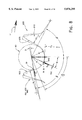
- FIG. 2 shows a typical cam-in-block ISO-606 compliant roller standard chain drive system 10, without a tensioner or chain guide, rotating in a clockwise direction as shown by arrow 11.
- the chain drive system 10 is comprised of a 25-tooth drive sprocket 20, a 50-tooth driven sprocket 30 and roller chain 40 having rollers 42.
- the roller chain 40 engages and wraps about sprockets 20 and 30 and has two spans extending between these sprockets, slack strand 44 and taut strand 46.
- the chain is under tension as shown by arrows 50, and distance D separates the centers of sprockets 20 and 30.
- a worn chain meshing with an ISO standard sprocket will have only one roller in driving contact and loaded at a maximum loading condition. This contact at maximum loading occurs as the roller enters the drive sprocket wrap 60 at engagement, shown in FIG. 2 as engaging roller 52.
- a second roller 54 is adjacent to the first roller 52 and is the next roller to mesh with the drive sprocket 20.
- the loading for roller 52 is composed primarily of the meshing impact loading and a major part of the chain tension 50 loading. The next several rollers in the wrap 60 forward of roller 52 share in the chain tension loading, but at a progressively decreasing rate.
- roller 52 serves to maintain a solid or hard contact of the roller with the sprocket tooth surface.
- Roller 56 the last roller in the drive wrap 60 just prior to entering the slack strand 44, will also be in hard contact with drive sprocket 20, but at some point higher up on the root surface 22.
- the remaining rollers will not be in hard contact with the sprocket teeth and will be free to vibrate against the sprocket tooth surface as they travel around the wrap, contributing to the broadband mechanical noise level.
- roller 59 in FIG. 2 the last roller in the wrap before it enters the taut strand, roller 59 in FIG. 2, is the roller in driving contact with the sprocket 30 at a maximum loading condition.
- roller 56, engaging roller 58 will be in hard contact with the root radius 32 of driven sprocket 30, but generally not at the root diameter.
- Chain drive systems including those using the ISO 606 compliant sprockets, have several components of undesirable noise.
- a major component of chain drive noise is the noise generated as the chain roller leaves the span and collides with the sprocket during meshing.
- the roller At meshing, the roller will have a radial impact component as it collides with the sprocket tooth at its root, and a tangential impact component as it collides with the engaging tooth flank.
- the loudness of the impact noise will be a function of the impact energy that must be absorbed during meshing. This impact energy is related to engine speed, chain mass, and the chain-sprocket engagement geometry, of which the engaging flank pressure angle is a major factor.
- the resultant meshing impact sound is repeated with a frequency generally equal to that of the frequency of the chain meshing with the sprocket.
- broadband mechanical noise caused in part by shaft torsional vibrations and slight dimensional inaccuracies between the chain and the sprockets.
- Contributing to a greater extent to broadband noise level is the intermittent or vibrating contact between the unloaded rollers and the sprocket teeth as the rollers travel around the wrap.
- the present invention satisfies this and other needs associated with conventional chain drive systems.
- the present invention will utilize an asymmetrical tooth profile with a decreased pressure angle for the engaging flank to reduce the roller-sprocket tangential impact force and the resultant noise level associated with the tangential roller impact.
- This asymmetrical tooth profile will also utilize a reduced roller seating angle at the disengaging flank to promote faster roller-sprocket separation as the roller exits the sprocket wrap.
- This reduced roller seating angle will also beneficially maintain the rollers in solid or hard contact with the sprocket tooth surface while the rollers are in the wrap, thereby contributing to a reduced broadband mechanical noise level.
- an inclined root surface is used to incorporate tooth space clearance to beneficially reduce the roller-sprocket radial impact force and the resultant noise level associated with radial roller impact.
- the inclined root surface will also beneficially maintain the roller-sprocket hard contact even as the chain pitch elongates with wear, further contributing to a reduced broadband mechanical noise level.
- the principal object of this invention is to provide a roller chain and sprocket drive system that reduces noise levels normally associated with chain drives by reducing the chain-sprocket engagement impact energy as the sprocket collects the rollers from the span.
- the present invention achieves this object by providing a sprocket having an asymmetrical tooth profile, each sprocket tooth comprising an engaging flank (which is also the drive flank for a driving sprocket), a disengaging flank (or coast flank for the same driving sprocket) opposite to the engaging flank of an adjacent tooth and an inclined root surface tangent to root radii that are disposed between the engaging and disengaging flanks of adjacent sprocket teeth.
- the optimized engaging flank pressure angle is beneficially decreased to reduce the tangential roller engagement force, thereby reducing the chain mesh impact noise contribution to the overall noise level.
- the inclined root surface defines an increasing or "uphill” root surface moving from the engaging flank of one tooth to the disengaging flank of the adjacent tooth.
- the inclined root surface defines a decreasing or "downhill" root surface moving from the engaging flank of one tooth to the disengaging flank of the adjacent tooth.
- the roller seating angle for the disengaging side is optimally reduced to promote faster separation of the roller from the sprocket as the roller leaves the sprocket to enter the span. It is also believed that this feature promotes hard contact between the rollers and the sprocket.
- tooth space clearance enables the rollers of a chain to maintain hard contact with the sprocket teeth as the rollers travel round the wrap, thereby reducing the broadband mechanical noise generated by the chain drive.
- Another advantage of the invention is that as the chain wears and the chain pitch elongates, the inclined root surface serves to move the roller radially outward, effectively locating the roller closer to the preferred pitch circle.
- Another advantage of the invention is that for a sprocket incorporating the "uphill" root surface feature, the inclined root surface requires less tooth thinning for the same amount of tooth space clearance.
- Another advantage of the invention is that for a given quantity of tooth space clearance and associated tooth thickness for a sprocket incorporating the "uphill" root surface feature, the asymmetrical tooth profile design will be stronger than pitch line clearance for conventional sprockets, which use a constant root diameter.
- Another advantage of the invention is that the asymmetrical sprocket tooth profile with the downhill inclined surface reduces the radial reaction force, thereby reducing the roller radial impact mesh noise contribution to the overall noise level.
- FIG. 1 is a front view of selected portions of the ISO 606 conventional roller chain sprocket tooth profile
- FIG. 2 is a front view of a conventional cam-in-block chain drive system without a tensioner or guide chain;
- FIG. 3 illustrates the variables considered in determining the impact energy that must be absorbed at the onset of roller and sprocket meshing
- FIG. 4 shows selected portions of an asymmetrical profile for a 25-tooth driving sprocket having an "uphill” inclined root surface that fits within the ISO profile envelope;
- FIG. 4a shows the pitch circle and pitch polygon for the sprocket of FIG. 4;
- FIG. 5 shows selected portions of an asymmetrical tooth profile for a 25-tooth sprocket without the inclined root surface feature
- FIG. 6 shows an asymmetrical profile for a 25-tooth driving sprocket having an "uphill” inclined root surface that is outside the ISO envelope;
- FIG. 6a shows selected portions of an asymmetrical profile for a 25-tooth driving sprocket having an "uphill” inclined root surface that is outside the ISO envelope;
- FIG. 7 illustrates a chain wrap associated with a 25-tooth driving sprocket engaged with a chain having an elongated pitch
- FIG. 7a illustrates an enlarged view of the engaging roller shown in FIG. 7;
- FIG. 8 shows selected portions of an asymmetrical profile for a 25-tooth driving sprocket having a "downhill” inclined root surface
- FIG. 9 shows selected portions of an asymmetrical profile for a 50-tooth driven sprocket having an "uphill” inclined root surface feature
- FIG. 10 illustrates a chain wrap associated with a 50-tooth driven sprocket
- FIG. 11 graphically illustrates, for several 25-tooth sprockets, the impact energy that must be absorbed during chain engagement as a function of engine speed
- FIG. 12 shows a cam-in-block camshaft chain drive system using asymmetrical tooth profile sprockets in a 25/50-tooth combination
- FIG. 13 shows a chain drive system using asymmetrical tooth profile sprockets in a 42/21-tooth combination
- FIG. 14 shows another chain drive system using asymmetrical tooth profile sprockets in a 42/21-tooth combination
- FIG. 15 is a table showing maximum and minimum roller seating and pressure angles for several ISO-606 compliant roller chain sprockets.
- FIG. 16 is a table showing pressure angles of various asymmetrical tooth profiles in relation to roller seating angles ⁇ .
- FIG. 3 shows variables that affect roller-sprocket impact noise.
- this impact noise is related to the roller impact energy E A (in Nm) occurring during the chain (roller) and sprocket meshing process: ##EQU1##
- the E A equation presumes the chain drive kinematics will conform generally to a quasi-static analytical model and that the roller-sprocket driving contact will occur at the tangency point TP for the flank and root radii as the sprocket collects a roller from the span.
- FIG. 15 shows, for several ISO sprockets, the maximum and minimum pressure angles ⁇ as a function of tooth angle A and maximum and minimum roller seating angles ⁇ .
- FIG. 15 shows, for several ISO sprockets, the maximum and minimum pressure angles ⁇ as a function of tooth angle A and maximum and minimum roller seating angles ⁇ .
- FIG. 3 shows a symmetrical 25-tooth maximum ISO-606 compliant sprocket 20 having a pressure angle ⁇ which is defined as the angle between a line A extending from the center of the engaging roller 52, when it is contacting the engaging tooth flank at the tangency point TP, through the center of the flank radius R f and a line B connecting the centers of the full seated roller 52, when it is seated on root diameter D 2 , and the center of the next meshing roller 54 as if it were also seated on root diameter D 2 in its engaging tooth space.
- the 25-tooth sprocket 20 of FIG. 3 will have a pressure angle ⁇ in the range of 14.6° to 24.6° as listed in the table of FIG. 15.
- FIG. 3 also shows the engagement path (phantom rollers) and the meshing contact position of roller 52 (solid) as the drive sprocket 20 rotates in the direction of arrow 11.
- FIG. 3 depicts the theoretical case with chain roller 52 seated on root diameter D 2 of a maximum material sprocket with both chain pitch and sprocket chordal pitch equal to theoretical pitch P.
- the noise occurring at the onset of roller engagement has a radial component F R as a result of roller 52 colliding with the root surface R i and a tangential component F T generated as the same roller 52 collides with the engaging tooth flank at point TP as the roller moves into driving contact. It is believed that the radial impact occurs first, with the tangential impact following nearly simultaneously.
- Roller impact velocity V A is shown to act through, and is substantially normal to, engaging flank tangency point TP with roller 52 in driving contact at point TP.
- the impact energy (E A ) equation accounts only for a tangential roller impact during meshing.
- the actual roller engagement presumed to have tangential and radial impacts (occurring in any order), would therefore seem to be a variance with the impact energy (E A ) equation.
- the application of this quasi-static model which is beneficially used as a directional tool, permits an analysis of those features that may be modified to reduce the impact energy occurring during the tangential roller-sprocket collision at the onset of meshing.
- the radial roller-sprocket collision during the engagement process, and its effect on the overall meshing noise levels, must be evaluated apart from the impact energy (E A ) equation.
- the evaluation has taken the form of firing engine NVH testing that compared the noise levels of sprockets having the standard ISO-606 tooth profile to sprockets having asymmetrical tooth profiles.
- FIG. 4 shows selected portions of an asymmetrical profile for a 25-tooth driving sprocket 100 of the present invention collecting a roller 90 from the taut strand of a roller chain (not shown) as it rotates in the direction of arrow 11.
- Each tooth 110 of sprocket 100 has an engaging flank 120 and a disengaging flank 130.
- the roller 90 enters into engagement with the sprocket 100 and seats on the root defined by roller seating radius R i .
- the engaging flank radius R f and the roller seating radius R i that is tangent to it satisfy the ISO 606 tooth profile specifications.
- the ISO symmetrical profile and the asymmetrical engaging side profile of the present embodiment are identical at maximum material conditions. As such, a maximum roller seated at the root diameter D 2 would have its center on the theoretical pitch circle.
- Roller seating radius R i is also tangent to an inclined root surface 140, at its radially outward, or upper end which defines a tooth space clearance TSC.
- Inclined root surface 140 is a flat surface of a finite length that can be inclined at any angle ⁇ needed to satisfy a specific geometry or to compensate for a given amount of pitch elongation.
- Inclined root surface angle ⁇ is measured from a line passing through the arc center of R i and the sprocket center to a second line passing through that arc center and normal to the lower edge of inclined root surface 140.
- the disengaging flank roller seating or root radius R i ' is also tangent to the inclined root surface 140.
- root radii R i and R i ' will typically have the same magnitude in this arrangement, the engaging flank radius R f and disengaging flank radius R f ' may have different values.
- engaging side roller seating angle ⁇ and disengaging side roller seating angle ⁇ ' replace the symmetrical ISO roller seating angle ⁇ .
- the tolerances for angles ⁇ and ⁇ ' are beneficially reduced such that the total tolerance for ⁇ and ⁇ ' does not exceed one-half the tolerance for ISO roller seating angle ⁇ .
- pressure angle ⁇ is related to ⁇ .
- the ISO maximum shown in phantom lines
- the asymmetrical maximum are identical and overlap when rotated into alignment.
- the outside diameter of the asymmetrical sprocket 100 is truncated.
- the tangential impact force component F T (but not the radial impact force F R ) shown in FIG. 4 is proportional to the roller impact velocity V A .
- a maximum engaging side roller seating angle ⁇ will minimize the pressure angle ⁇ at chain engagement for the tooth collecting the roller from the span. This will also reduce the tangential impact force component F T and thus the impact noise contribution to the overall noise level.
- Roller seating angles ⁇ ' and ⁇ of FIG. 4 could be equivalent. However, it is believed to be advantageous to have a maximum value for angle ⁇ ', which is equal to ⁇ min /2. This reduced seating angle ⁇ ' serves to promote faster separation when the roller leaves the sprocket and enters the span, and it also helps to maintain "hard” roller-sprocket contact for rollers in the wrap. Accordingly, disengaging side roller seating angle ⁇ ' is shown to be a minimum angle.
- FIG. 4a shows a portion of a pitch circle A and related pitch polygon B for the theoretical pitch P (maximum) of the 25-tooth 8 mm pitch sprocket of FIG. 4. It also shows the pitch circle C and pitch polygon D for a sprocket with a slightly longer chordal pitch P+ ⁇ P, demonstrating the preferred sprocket interface for a worn chain.
- the roller 90 in FIG. 4 moves up the inclined root surface 140, its center defines a new pitch circle that is greater than the theoretical pitch circle.
- the amount that the pitch circle increases as roller 90 moves radially outward up the inclined root surface 140 is a function of the inclined root surface angle ⁇ and the amount of tooth space clearance TSC.
- FIG. 5 shows a further embodiment of the present invention, sprocket 200.
- the sprocket 200 does not have the inclined root surface or tooth space clearance of the embodiment shown in FIG. 4.
- FIG. 6 shows selected portions of a 25-tooth asymmetrical driving sprocket 300 according to the present invention that is outside the ISO specifications.
- angle ⁇ is greater than ⁇ max /2.
- a maximum value for angle ⁇ ' for the adjacent tooth, shown in FIG. 6 as ⁇ ' max is equal to ⁇ min /2.
- This arrangement produces improved NVH characteristics, as the pressure angle ⁇ , and thus the impact energy E A for the chain drive are reduced.
- a maximum value for ⁇ ' for sprocket 400 shown as ⁇ ' max , is less than ⁇ min /2.
- sprocket 400 of FIG. 6a also falls outside the ISO specifications.
- FIG. 7 shows the roller chain wrap for an asymmetrical profile for a 25-tooth driving sprocket 500 in a 25/50-tooth sprocket chain drive system.
- a new chain at theoretical pitch would have all rollers 90 in contact with the root surfaces 550 of a max tooth-profile sprocket for the full wrap 560.
- the sprocket 500 of FIG. 7 provides tooth space clearance TSC to accommodate a specified degree of chain pitch elongation ⁇ P.
- FIG. 7a more clearly shows the progression of the rollers 90 in the tooth spaces as the rollers travel around the sprocket 500 in the wrap.
- the inclined root surface for the driving sprocket is reversed.
- the inclined root surface 640 of driving sprocket 600 is disposed radially inward from the engaging flank 620 to the disengaging flank 630 of the tooth space, or "downhill.”
- the inclined surface 640 defines a decreasing root surface.
- the ISO standard sprocket captures the chain rollers in the valley of the root radius R i as the teeth and rollers mesh. Therefore, the rollers impact the root radius R i at the root diameter D 2 , producing the radial reaction force F R shown in FIG. 3
- the asymmetrical tooth profile incorporating a "downhill” inclined root surface provides for improved meshing at engagement. Specifically, the roller progression is downhill for a worn chain as its rollers travel around the wrap. In this arrangement, it is believed that the radial reaction force F R is reduced and a degree of damping will occur, with the chain link plates absorbing the difference between F R (ISO) and F.sub. ⁇ , shown in FIG. 8.
- FIG. 16 lists several profiles having pressure angles ⁇ that are reduced from the ISO ⁇ angles, the selection of which would be determined by that pressure angle found to be the most beneficial for a specific chain drive. It is contemplated that other angles less than the ISO ⁇ may also be beneficially used.
- the roller 90 shown in FIG. 8 has its center on the theoretical pitch circle when it is in contact with the tooth surface at point B.
- the engaging roller seating radius R i may equal the disengaging roller seating radius R i ' in conformity with the ISO standard. Accordingly, these radii would be slightly larger than a maximum roller radius.
- a further embodiment would have the roller center on the theoretical pitch diameter when the roller is seated on the root diameter D 2 .
- Yet another embodiment would place the roller center on the theoretical pitch diameter when the roller contacts the root surface at some point between point B and D 2 .
- FIG. 9 shows an asymmetrical tooth profile for a 50-tooth driven sprocket 700 incorporating an "uphill" inclined root surface 740. Whether the incline orientation is considered uphill or downhill is a function of the incline surface position with respect to the roller when the roller is in the driving contact.
- the inclined root surface is disposed radially outward from the disengaging (drive) flank 730 to the engaging flank 720. Accordingly, the roller enters the driven sprocket wrap from the slack strand to a downhill incline which is advantageous for reduced radial impact, but the roller progression in the wrap as the chain wear occurs is radially outward in the preferred direction, or uphill, from the driving contact position.
- the engaging roller seating angle ⁇ is greater than ⁇ max /2, and the disengaging roller seating angle ⁇ ' is less than ⁇ min /2.
- Roller 90 and coast flank 720 contact at the onset of engagement will theoretically occur only when chain wear is at the maximum chain pitch elongation ⁇ P.
- a new chain at theoretical pitch P would have all rollers in contact with root diameter D 2 of the sprocket 700 shown in FIG. 9 for a max material sprocket.
- FIG. 10 shows the wrap angle 870 for a 50-tooth driven sprocket 800 with tooth space clearance TSC in a 25/50-tooth sprocket chain drive system.
- FIG. 10 also shows the corresponding chain pitch elongation ⁇ P that can be accommodated.
- FIG. 16 lists the maximum engaging side roller seating angles ⁇ and related pressure angles ⁇ for three families of asymmetrical profiles according to the present invention. These pressure angles ⁇ are described according to the number of sprocket teeth Z and corresponding tooth angle A, and the engaging side roller seating angle ⁇ , as contrasted to the pressure angle values for the ISO-606 compliant tooth profiles listed in FIG. 15.
- the asymmetrical profiles are merely illustrative of sprockets according to the present invention; therefore, alternative sprockets having other profiles may have better NVH characteristics for a specific drive.
- empirical analysis demonstrates that engagement noise levels decrease for the asymmetrical profiles as the pressure angle ⁇ is reduced from the ISO standard.
- FIG. 11 graphically illustrates the impact energy E A as a function of engine speed during the engagement of an 8 mm pitch roller chain to a 25-tooth sprocket.
- the four E A curves shown are for ISO maximum and minimum pressure angles, and asymmetrical maximum and minimum pressure angles. These curves represent the theoretical case for maximum and minimum material sprockets and a chain at theoretical pitch.
- the maximum impact energy level for the asymmetrical (MAX ASYM) profile is less than the ISO maximum (MAX ISO) as well as the ISO minimum (MIN ISO).
- FIG. 12 shows a typical cam-in-block camshaft chain drive system 900 using asymmetrical tooth profile sprockets in a 25/50-tooth sprocket combination.
- the 25-tooth drive sprocket 910 for this chain drive arrangement is fastened to a crankshaft and, accordingly, runs at crankshaft speed.
- FIG. 13 Another chain drive application for asymmetrical-profile sprockets is a balance shaft drive 900' as shown in FIG. 13.
- the 42-tooth drive sprocket 910' is fastened to a crankshaft.
- the 21-tooth driven sprocket 920' is fastened to the balance shaft, and will, therefore, run at twice crankshaft speed.
- the driven shaft will normally drive a second counter-rotating balance shaft through a 1:1 gear drive.
- FIG. 14 shows another typical balance shaft drive 900" using the same 42/21-tooth sprocket combination in a 4-sprocket chain drive system, which uses an idler sprocket 940" to achieve the reverse rotation of the balance shafts.
- Balance shaft sprockets 920" and 930" are fastened to counter-rotating balance shafts that run at twice crankshaft speed serving to counterbalance the second order free (out-of-balance) forces for an in-line 4-cylinder engine.
- Rollers X and Y are the engaging rollers for the right hand and left hand balance shaft sprockets 930" and 920", respectively.
- roller engagement occurs at the same instant, and this can be managed by slightly changing the chain geometry by increasing or decreasing the chain strand offset between the two sprockets, for instance.
- the 21-tooth sprockets 930" and 920" contribute a greater degree to the overall noise levels, all 4 sprockets contribute as a consequence of roller-sprocket meshing. So, it is preferable to design the drive to stagger the roller meshing for all the sprockets.
- tooth profile features shown and described above can be altered slightly without substantially deviating from the chain and sprocket meshing kinematics that produce the noise reduction advantages with this invention.
- slight changes to the profile might be done for manufacturing, quality control reasons, or to improve part dimensioning.
- Another example would be to approximate the engaging asymmetrical flank profile by an involute form, and the disengaging asymmetrical flank profile could be approximated by a different involute form.
Abstract
Description
Claims (24)
β≧α.sub.NOMINAL /2,
α.sub.MAX /2≧β≧α.sub.NOMINAL /2,
β'≦α.sub.NOMINAL /2,
α.sub.MIN /2≦β'≦α.sub.NOMINAL /2,
β≧α.sub.NOMINAL /2,
β'≦α.sub.NOMINAL /2,
α.sub.MAX /2≧β≧α.sub.NOMINAL /2,
α.sub.MIN /2≦β'≦α.sub.NOMINAL /2,
β≧α.sub.NOMINAL /2,
β'≦α.sub.NOMINAL /2,
α.sub.MAX /2≧β≧α.sub.NOMINAL /2,
α.sub.MIN /2≦β'≦α.sub.NOMINAL /2,
Priority Applications (8)
| Application Number | Priority Date | Filing Date | Title |
|---|---|---|---|
| EP97908640A EP0870131B1 (en) | 1996-01-23 | 1997-01-23 | Roller chain drive system having improved noise characteristics |
| DE29724295U DE29724295U1 (en) | 1996-01-23 | 1997-01-23 | Roller sprocket |
| DE69715370T DE69715370T2 (en) | 1996-01-23 | 1997-01-23 | ROLLER CHAIN DRIVE DEVICE WITH IMPROVED NOISE BEHAVIOR |
| US08/787,675 US5876295A (en) | 1996-01-23 | 1997-01-23 | Roller chain drive system having improved noise characteristics |
| BR9707182A BR9707182A (en) | 1996-01-23 | 1997-01-23 | Rolling chain drive system with improved noise characteristics |
| ES97908640T ES2183141T3 (en) | 1996-01-23 | 1997-01-23 | ROLLER CHAIN DRIVING SYSTEM WITH IMPROVED NOISE CHARACTERISTICS. |
| JP52711497A JP4195090B2 (en) | 1996-01-23 | 1997-01-23 | Roller chain drive system with improved noise characteristics |
| PCT/US1997/001494 WO1997027411A1 (en) | 1996-01-23 | 1997-01-23 | Roller chain drive system having improved noise characteristics |
Applications Claiming Priority (2)
| Application Number | Priority Date | Filing Date | Title |
|---|---|---|---|
| US1043596P | 1996-01-23 | 1996-01-23 | |
| US08/787,675 US5876295A (en) | 1996-01-23 | 1997-01-23 | Roller chain drive system having improved noise characteristics |
Publications (1)
| Publication Number | Publication Date |
|---|---|
| US5876295A true US5876295A (en) | 1999-03-02 |
Family
ID=26681172
Family Applications (1)
| Application Number | Title | Priority Date | Filing Date |
|---|---|---|---|
| US08/787,675 Expired - Lifetime US5876295A (en) | 1996-01-23 | 1997-01-23 | Roller chain drive system having improved noise characteristics |
Country Status (1)
| Country | Link |
|---|---|
| US (1) | US5876295A (en) |
Cited By (22)
| Publication number | Priority date | Publication date | Assignee | Title |
|---|---|---|---|---|
| WO1999049239A1 (en) | 1998-03-26 | 1999-09-30 | Cloyes Gear And Products, Inc. | Random engagement roller chain sprocket with staged meshing and root relief to provide improved noise characteristics |
| US6155943A (en) * | 1997-10-03 | 2000-12-05 | Borgwarner Inc. | Randomized sprocket for roller chain |
| US6213905B1 (en) | 1999-07-01 | 2001-04-10 | Borgwarner Inc. | Roller chain sprockets oriented to minimize strand length variation |
| EP1203902A2 (en) | 2000-11-01 | 2002-05-08 | BorgWarner Inc. | Roller chain sprocket for preventing substantially radial impact with chain rollers |
| US6415532B1 (en) | 2000-07-31 | 2002-07-09 | The Toro Company | Drive sprocket for a roller chain for material removal implement |
| US20020132689A1 (en) * | 1996-12-19 | 2002-09-19 | Young James D. | Roller chain sprocket with added chordal pitch reduction |
| US20030087714A1 (en) * | 2001-11-06 | 2003-05-08 | Borgwarner Inc. | Tension-reducing random sprocket |
| WO2004059194A1 (en) | 2002-12-19 | 2004-07-15 | Cloyes Gear And Products, Inc. | Asymmetric sprocket assembly with metal cushion rings |
| US20040185977A1 (en) * | 1996-12-19 | 2004-09-23 | Cloyes Gear And Products, Inc. | Random engagement roller chain sprocket and timing chain system including same |
| US20070087880A1 (en) * | 2005-10-14 | 2007-04-19 | Borgwarner Inc. | Sprocket tooth profile for a roller or bush chain |
| US20080312017A1 (en) * | 2007-05-11 | 2008-12-18 | Young James D | Inverted tooth chain sprocket with frequency modulated meshing |
| US20090105024A1 (en) * | 2007-10-22 | 2009-04-23 | Tsubakimoto Chain Co. | Chain transmission |
| US20090241875A1 (en) * | 2008-03-26 | 2009-10-01 | Labere Rikki Scott | Apparatus and methods for continuous variable valve timing |
| US20100156170A1 (en) * | 2008-12-18 | 2010-06-24 | Jianping Zheng | Sprocketed drive assembly for track-type machine |
| US20100167857A1 (en) * | 2007-06-20 | 2010-07-01 | Borgwarner Inc. | Resonance tension reducing sprocket with combined radial variation and sprocket wrap |
| US20100227720A1 (en) * | 2008-03-06 | 2010-09-09 | Borgwarner Inc. | Sprocket randomization for enhanced nvh control |
| US20100292038A1 (en) * | 2007-09-28 | 2010-11-18 | Borgwarner Inc. | Multiple Tension Reducing Sprockets in a Chain and Sprocket System |
| US20130345006A1 (en) * | 2012-06-21 | 2013-12-26 | Tai-Her Yang | Chainwheel Enabling Positive Rotational Transmission and Reverse Rotational Sliding Features |
| US20170191558A1 (en) * | 2014-05-29 | 2017-07-06 | Miranda & Irmaco, Lda. | Drivetrain system and use thereof |
| US20170370458A1 (en) * | 2016-06-27 | 2017-12-28 | Shimano Inc. | Bicycle sprocket and bicycle sprocket assembly |
| US10907721B2 (en) * | 2015-12-09 | 2021-02-02 | Borgwarner Inc. | Non-prevalent order random sprocket |
| US11009114B2 (en) * | 2017-11-06 | 2021-05-18 | Tsubakimoto Chain Co. | Sprocket and transmission mechanism |
Citations (60)
| Publication number | Priority date | Publication date | Assignee | Title |
|---|---|---|---|---|
| US320734A (en) * | 1885-06-23 | Belt-gearing | ||
| US536813A (en) * | 1895-04-02 | Sprocket-wheel | ||
| US698991A (en) * | 1901-04-13 | 1902-04-29 | Morse Chain Co | Chain-wheel. |
| US717976A (en) * | 1901-11-07 | 1903-01-06 | Link Belt Engineering Company | Sprocket-wheel for drive-chains. |
| US984509A (en) * | 1909-06-12 | 1911-02-14 | Sam A Crowder | Sprocket driving mechanism. |
| US1630313A (en) * | 1925-04-30 | 1927-05-31 | American Manganese Steel Co | Sprocket wheel |
| US1808369A (en) * | 1926-06-21 | 1931-06-02 | Celotex Company | Sprocket |
| US2382740A (en) * | 1943-07-10 | 1945-08-14 | Fred P Noffsinger | Sprocket wheel |
| US2385923A (en) * | 1941-10-23 | 1945-10-02 | Chain Belt Company Milwaukee | Conveyer chain |
| US2934200A (en) * | 1956-10-15 | 1960-04-26 | Gen Motors Corp | Conveyor system |
| US3130791A (en) * | 1963-02-04 | 1964-04-28 | Lloyd K Schmidt | Endless chain drive unit |
| US3194609A (en) * | 1964-03-30 | 1965-07-13 | Thurlow Lloyd | Sprocket and chain drive |
| US3298406A (en) * | 1964-05-15 | 1967-01-17 | Herbert V Erickson | Chain saw chain |
| US3377875A (en) * | 1966-05-09 | 1968-04-16 | Gen Motors Corp | Chain drive power transmitting mechanism |
| US3448629A (en) * | 1968-06-20 | 1969-06-10 | Amsted Ind Inc | Chain and sprocket drive |
| US3495468A (en) * | 1968-11-21 | 1970-02-17 | Gen Motors Corp | Chain drive |
| US3604755A (en) * | 1969-07-24 | 1971-09-14 | Cincinnati Mine Machinery Co | Cutter bar, cutter chain and sprocket assembly |
| US3824869A (en) * | 1972-09-25 | 1974-07-23 | Standard Tool & Mfg Co | Chain drive having pivoted drive teeth |
| US3956943A (en) * | 1972-10-25 | 1976-05-18 | Maeda Industries, Ltd. | Bicycle sprocket wheel |
| SU515906A1 (en) * | 1974-09-09 | 1976-05-30 | Гомельский Ордена Ленина Завод Сельскохозяйственного Машиностроения | Sprocket for roller or sleeve chain |
| US4016772A (en) * | 1975-09-22 | 1977-04-12 | Caterpillar Tractor Co. | Sprocket member configuration |
| US4036071A (en) * | 1976-04-02 | 1977-07-19 | Hollis And Company | Sprocket and method for producing same |
| SU595565A1 (en) * | 1975-09-01 | 1978-02-28 | Gotovtsev Aleksandr A | Sprocket |
| US4089406A (en) * | 1974-10-09 | 1978-05-16 | Fritz Teske | Chain drive |
| US4099423A (en) * | 1977-06-21 | 1978-07-11 | Max Mullins | Compatible sprocket and chain system |
| US4116081A (en) * | 1977-05-25 | 1978-09-26 | Caterpillar Tractor Co. | Sprocket profile |
| US4168634A (en) * | 1977-05-27 | 1979-09-25 | General Motors Corporation | Chain and sprocket power transmitting mechanism |
| US4174642A (en) * | 1978-02-09 | 1979-11-20 | Gehl Company | Chain drive including sprocket having alternate wide and narrow teeth |
| US4181033A (en) * | 1976-12-28 | 1980-01-01 | Shimano Industrial Company Limited | Sprocket for bicycles |
| US4200000A (en) * | 1978-10-04 | 1980-04-29 | Societe Suisse Pour L'industrie Horlogere Management Services S.A. | Gear train |
| US4207777A (en) * | 1978-11-07 | 1980-06-17 | Societe Suisse pour l'Industrie Horlogere Mangagement Services S.A. | One way gear train |
| US4274184A (en) * | 1977-10-20 | 1981-06-23 | Svein Nordtvedt | Mesh distribution wheels |
| US4294132A (en) * | 1977-09-29 | 1981-10-13 | Fabryka Obrabiarek Precyzyjnych "Ponar-Bruszkow" | Cylindrical gear with helical teeth |
| US4378965A (en) * | 1979-02-28 | 1983-04-05 | Konishiroku Photo Industry Co., Ltd. | Sprocket wheel for photographic camera |
| US4401420A (en) * | 1979-09-14 | 1983-08-30 | Hitachi, Ltd. | Male and female screw rotor assembly with specific tooth flanks |
| US4492030A (en) * | 1981-08-24 | 1985-01-08 | Beerens Cornelis J | Chain saw bars |
| US4521207A (en) * | 1982-06-11 | 1985-06-04 | Royce H. Husted | Incrementally variable transmission |
| US4522611A (en) * | 1982-12-27 | 1985-06-11 | Esco Corporation | Sprocket assembly with replaceable teeth |
| US4531926A (en) * | 1983-07-11 | 1985-07-30 | Reeves Jr James B | Adjustable pitch sprocket |
| US4559028A (en) * | 1983-07-11 | 1985-12-17 | Reeves Jr James B | Adjustment pitch sprocket |
| US4571218A (en) * | 1983-07-11 | 1986-02-18 | Reeves Jr James B | Adjustable pitch sprocket |
| US4653340A (en) * | 1986-03-03 | 1987-03-31 | Pitney Bowes Inc. | Beveled spur gear |
| US4758209A (en) * | 1987-04-01 | 1988-07-19 | Borg-Warner Automotive, Inc. | Silent timing chain and sprocket system |
| US4813916A (en) * | 1988-03-08 | 1989-03-21 | Sachs-Huret S.A. | Sprocket having teeth of improved shape and a cycle free-wheel including said sprocket |
| US4889521A (en) * | 1987-10-21 | 1989-12-26 | Shimano Industrial Company Limited | Multistage sprocket assembly for a bicycle |
| US4911032A (en) * | 1988-10-03 | 1990-03-27 | Moore Push-Pin Company | One-way gear |
| US4915604A (en) * | 1987-08-11 | 1990-04-10 | Hitachi, Ltd. | Rotors for a screw fluid machine |
| US4915675A (en) * | 1989-02-28 | 1990-04-10 | Avramidis Stellios A | Pitch equalized chain with frequency modulated engagement |
| US4969371A (en) * | 1989-01-26 | 1990-11-13 | Renold, Inc. | Gear type flexible coupling |
| US5022280A (en) * | 1988-03-29 | 1991-06-11 | Boiko Leonid S | Novikov gearing |
| US5073151A (en) * | 1988-11-07 | 1991-12-17 | Shimano Industrial Co., Ltd. | Multi-speed sprocket assembly for bicycle |
| US5123878A (en) * | 1990-01-20 | 1992-06-23 | Shimano Industrial Company Limited | Multistage sprocket assembly |
| US5133695A (en) * | 1989-02-15 | 1992-07-28 | Maeda Industries, Ltd. | Bicycle multiple chainwheel |
| US5154674A (en) * | 1990-04-25 | 1992-10-13 | Borg-Warner Automotive Transmission & Engine Components Corporation | Power transmission chain constructed with asymmetrical links |
| US5162022A (en) * | 1990-09-18 | 1992-11-10 | Maeda Industries, Ltd. | Multiple sprocket assembly for bicycle |
| US5163826A (en) * | 1990-10-23 | 1992-11-17 | Cozens Eric E | Crescent gear pump with hypo cycloidal and epi cycloidal tooth shapes |
| US5318483A (en) * | 1993-05-14 | 1994-06-07 | American Longwall Face Conveyors, Inc. | Sprocket with asymmetrical teeth for mining conveyors |
| US5397278A (en) * | 1993-06-30 | 1995-03-14 | Tsubakimoto Chain Co. | Sprocket for roller chain |
| US5437582A (en) * | 1993-06-03 | 1995-08-01 | Campagnolo S.R.L. | Sprocket assembly for bicycles |
| US5503598A (en) * | 1993-09-13 | 1996-04-02 | Fichtel & Sachs Ag | Derailleur arrangement, in particular for bicycles |
-
1997
- 1997-01-23 US US08/787,675 patent/US5876295A/en not_active Expired - Lifetime
Patent Citations (63)
| Publication number | Priority date | Publication date | Assignee | Title |
|---|---|---|---|---|
| US320734A (en) * | 1885-06-23 | Belt-gearing | ||
| US536813A (en) * | 1895-04-02 | Sprocket-wheel | ||
| US698991A (en) * | 1901-04-13 | 1902-04-29 | Morse Chain Co | Chain-wheel. |
| US717976A (en) * | 1901-11-07 | 1903-01-06 | Link Belt Engineering Company | Sprocket-wheel for drive-chains. |
| US984509A (en) * | 1909-06-12 | 1911-02-14 | Sam A Crowder | Sprocket driving mechanism. |
| US1630313A (en) * | 1925-04-30 | 1927-05-31 | American Manganese Steel Co | Sprocket wheel |
| US1808369A (en) * | 1926-06-21 | 1931-06-02 | Celotex Company | Sprocket |
| US2385923A (en) * | 1941-10-23 | 1945-10-02 | Chain Belt Company Milwaukee | Conveyer chain |
| US2382740A (en) * | 1943-07-10 | 1945-08-14 | Fred P Noffsinger | Sprocket wheel |
| US2934200A (en) * | 1956-10-15 | 1960-04-26 | Gen Motors Corp | Conveyor system |
| US3130791A (en) * | 1963-02-04 | 1964-04-28 | Lloyd K Schmidt | Endless chain drive unit |
| US3194609A (en) * | 1964-03-30 | 1965-07-13 | Thurlow Lloyd | Sprocket and chain drive |
| US3298406A (en) * | 1964-05-15 | 1967-01-17 | Herbert V Erickson | Chain saw chain |
| US3377875A (en) * | 1966-05-09 | 1968-04-16 | Gen Motors Corp | Chain drive power transmitting mechanism |
| US3448629A (en) * | 1968-06-20 | 1969-06-10 | Amsted Ind Inc | Chain and sprocket drive |
| US3495468A (en) * | 1968-11-21 | 1970-02-17 | Gen Motors Corp | Chain drive |
| US3604755A (en) * | 1969-07-24 | 1971-09-14 | Cincinnati Mine Machinery Co | Cutter bar, cutter chain and sprocket assembly |
| US3824869A (en) * | 1972-09-25 | 1974-07-23 | Standard Tool & Mfg Co | Chain drive having pivoted drive teeth |
| US3956943A (en) * | 1972-10-25 | 1976-05-18 | Maeda Industries, Ltd. | Bicycle sprocket wheel |
| SU515906A1 (en) * | 1974-09-09 | 1976-05-30 | Гомельский Ордена Ленина Завод Сельскохозяйственного Машиностроения | Sprocket for roller or sleeve chain |
| US4089406A (en) * | 1974-10-09 | 1978-05-16 | Fritz Teske | Chain drive |
| SU595565A1 (en) * | 1975-09-01 | 1978-02-28 | Gotovtsev Aleksandr A | Sprocket |
| US4016772A (en) * | 1975-09-22 | 1977-04-12 | Caterpillar Tractor Co. | Sprocket member configuration |
| USRE30018E (en) * | 1975-09-22 | 1979-06-05 | Caterpillar Tractor Co. | Sprocket member configuration |
| US4036071A (en) * | 1976-04-02 | 1977-07-19 | Hollis And Company | Sprocket and method for producing same |
| US4181033A (en) * | 1976-12-28 | 1980-01-01 | Shimano Industrial Company Limited | Sprocket for bicycles |
| US4116081A (en) * | 1977-05-25 | 1978-09-26 | Caterpillar Tractor Co. | Sprocket profile |
| US4168634A (en) * | 1977-05-27 | 1979-09-25 | General Motors Corporation | Chain and sprocket power transmitting mechanism |
| US4099423A (en) * | 1977-06-21 | 1978-07-11 | Max Mullins | Compatible sprocket and chain system |
| US4294132A (en) * | 1977-09-29 | 1981-10-13 | Fabryka Obrabiarek Precyzyjnych "Ponar-Bruszkow" | Cylindrical gear with helical teeth |
| US4274184A (en) * | 1977-10-20 | 1981-06-23 | Svein Nordtvedt | Mesh distribution wheels |
| US4174642A (en) * | 1978-02-09 | 1979-11-20 | Gehl Company | Chain drive including sprocket having alternate wide and narrow teeth |
| US4200000A (en) * | 1978-10-04 | 1980-04-29 | Societe Suisse Pour L'industrie Horlogere Management Services S.A. | Gear train |
| US4207777A (en) * | 1978-11-07 | 1980-06-17 | Societe Suisse pour l'Industrie Horlogere Mangagement Services S.A. | One way gear train |
| US4378965A (en) * | 1979-02-28 | 1983-04-05 | Konishiroku Photo Industry Co., Ltd. | Sprocket wheel for photographic camera |
| US4401420A (en) * | 1979-09-14 | 1983-08-30 | Hitachi, Ltd. | Male and female screw rotor assembly with specific tooth flanks |
| US4492030A (en) * | 1981-08-24 | 1985-01-08 | Beerens Cornelis J | Chain saw bars |
| US4521207A (en) * | 1982-06-11 | 1985-06-04 | Royce H. Husted | Incrementally variable transmission |
| US4522611A (en) * | 1982-12-27 | 1985-06-11 | Esco Corporation | Sprocket assembly with replaceable teeth |
| US4531926A (en) * | 1983-07-11 | 1985-07-30 | Reeves Jr James B | Adjustable pitch sprocket |
| US4559028A (en) * | 1983-07-11 | 1985-12-17 | Reeves Jr James B | Adjustment pitch sprocket |
| US4571218A (en) * | 1983-07-11 | 1986-02-18 | Reeves Jr James B | Adjustable pitch sprocket |
| US4653340A (en) * | 1986-03-03 | 1987-03-31 | Pitney Bowes Inc. | Beveled spur gear |
| US4758209A (en) * | 1987-04-01 | 1988-07-19 | Borg-Warner Automotive, Inc. | Silent timing chain and sprocket system |
| US4915604A (en) * | 1987-08-11 | 1990-04-10 | Hitachi, Ltd. | Rotors for a screw fluid machine |
| US4889521A (en) * | 1987-10-21 | 1989-12-26 | Shimano Industrial Company Limited | Multistage sprocket assembly for a bicycle |
| US4889521B1 (en) * | 1987-10-21 | 1995-05-09 | Shimano Industrial Co | Multistage sprocket assembly for a bicycle |
| US4813916A (en) * | 1988-03-08 | 1989-03-21 | Sachs-Huret S.A. | Sprocket having teeth of improved shape and a cycle free-wheel including said sprocket |
| US5022280A (en) * | 1988-03-29 | 1991-06-11 | Boiko Leonid S | Novikov gearing |
| US4911032A (en) * | 1988-10-03 | 1990-03-27 | Moore Push-Pin Company | One-way gear |
| US5073151A (en) * | 1988-11-07 | 1991-12-17 | Shimano Industrial Co., Ltd. | Multi-speed sprocket assembly for bicycle |
| US4969371A (en) * | 1989-01-26 | 1990-11-13 | Renold, Inc. | Gear type flexible coupling |
| US5133695A (en) * | 1989-02-15 | 1992-07-28 | Maeda Industries, Ltd. | Bicycle multiple chainwheel |
| US4915675A (en) * | 1989-02-28 | 1990-04-10 | Avramidis Stellios A | Pitch equalized chain with frequency modulated engagement |
| US4915675B1 (en) * | 1989-02-28 | 1998-12-29 | Borg Warner Automotive | Pitch equalized chain with frequency modulated engagement |
| US5123878A (en) * | 1990-01-20 | 1992-06-23 | Shimano Industrial Company Limited | Multistage sprocket assembly |
| US5154674A (en) * | 1990-04-25 | 1992-10-13 | Borg-Warner Automotive Transmission & Engine Components Corporation | Power transmission chain constructed with asymmetrical links |
| US5162022A (en) * | 1990-09-18 | 1992-11-10 | Maeda Industries, Ltd. | Multiple sprocket assembly for bicycle |
| US5163826A (en) * | 1990-10-23 | 1992-11-17 | Cozens Eric E | Crescent gear pump with hypo cycloidal and epi cycloidal tooth shapes |
| US5318483A (en) * | 1993-05-14 | 1994-06-07 | American Longwall Face Conveyors, Inc. | Sprocket with asymmetrical teeth for mining conveyors |
| US5437582A (en) * | 1993-06-03 | 1995-08-01 | Campagnolo S.R.L. | Sprocket assembly for bicycles |
| US5397278A (en) * | 1993-06-30 | 1995-03-14 | Tsubakimoto Chain Co. | Sprocket for roller chain |
| US5503598A (en) * | 1993-09-13 | 1996-04-02 | Fichtel & Sachs Ag | Derailleur arrangement, in particular for bicycles |
Non-Patent Citations (4)
| Title |
|---|
| DE vol. 46, Mechanical Design and Synthesis ASME 1992, entitled On The Dynamic Analysis Of Roller Chain Drives: Part 1 Theory. (pp. 431 439). * |
| DE-vol. 46, Mechanical Design and Synthesis ASME 1992, entitled "On The Dynamic Analysis Of Roller Chain Drives: Part 1--Theory." (pp. 431-439). |
| International Standard ISO 606:1994(E), entitled "Short-pitch transmission precision roller chains and chain wheels." (19 pgs.). |
| International Standard ISO 606:1994(E), entitled Short pitch transmission precision roller chains and chain wheels. (19 pgs.). * |
Cited By (43)
| Publication number | Priority date | Publication date | Assignee | Title |
|---|---|---|---|---|
| US20040185977A1 (en) * | 1996-12-19 | 2004-09-23 | Cloyes Gear And Products, Inc. | Random engagement roller chain sprocket and timing chain system including same |
| US20020132689A1 (en) * | 1996-12-19 | 2002-09-19 | Young James D. | Roller chain sprocket with added chordal pitch reduction |
| US6761657B2 (en) * | 1996-12-19 | 2004-07-13 | Cloyes Gear And Products, Inc. | Roller chain sprocket with added chordal pitch reduction |
| US7416500B2 (en) | 1996-12-19 | 2008-08-26 | Cloyes Gear And Products, Inc. | Random engagement roller chain sprocket and timing chain system including same |
| US6155943A (en) * | 1997-10-03 | 2000-12-05 | Borgwarner Inc. | Randomized sprocket for roller chain |
| US5997424A (en) * | 1998-03-26 | 1999-12-07 | Cloyes Gear And Products, Inc. | Random engagement roller chain sprocket with staged meshing and root relief to provide improved noise characteristics |
| WO1999049239A1 (en) | 1998-03-26 | 1999-09-30 | Cloyes Gear And Products, Inc. | Random engagement roller chain sprocket with staged meshing and root relief to provide improved noise characteristics |
| US6213905B1 (en) | 1999-07-01 | 2001-04-10 | Borgwarner Inc. | Roller chain sprockets oriented to minimize strand length variation |
| US6415532B1 (en) | 2000-07-31 | 2002-07-09 | The Toro Company | Drive sprocket for a roller chain for material removal implement |
| EP1203902A2 (en) | 2000-11-01 | 2002-05-08 | BorgWarner Inc. | Roller chain sprocket for preventing substantially radial impact with chain rollers |
| US6736744B1 (en) | 2000-11-01 | 2004-05-18 | Borgwarner, Inc. | Roller chain sprocket for preventing substantially radial impact with chain rollers |
| US8066602B2 (en) | 2001-11-06 | 2011-11-29 | Borgwarner Inc. | Tension-reducing random sprocket |
| EP1308646A3 (en) * | 2001-11-06 | 2005-01-19 | BorgWarner Inc. | Tension-reducing random sprocket |
| US20100151978A1 (en) * | 2001-11-06 | 2010-06-17 | Borgwarner, Inc. | Tension-Reducing Random Sprocket |
| US7125356B2 (en) * | 2001-11-06 | 2006-10-24 | Borgwarner Inc. | Tension-reducing random sprocket |
| US20060240925A1 (en) * | 2001-11-06 | 2006-10-26 | Borgwarner Inc. | Tension-Reducing Random Sprocket |
| EP1722131A3 (en) * | 2001-11-06 | 2008-04-23 | Borgwarner, Inc. | Tension-Reducing Random Sprocket |
| US7654925B2 (en) | 2001-11-06 | 2010-02-02 | Borgwarner Inc. | Tension-reducing random sprocket |
| US20030087714A1 (en) * | 2001-11-06 | 2003-05-08 | Borgwarner Inc. | Tension-reducing random sprocket |
| WO2003048604A2 (en) | 2001-12-04 | 2003-06-12 | Cloyes Gear And Products, Inc. | Roller chain sprocket with added chordal pitch reduction |
| US20040204274A1 (en) * | 2002-12-19 | 2004-10-14 | Young James D | Asymmetric sprocket assembly with metal cushion rings |
| WO2004059194A1 (en) | 2002-12-19 | 2004-07-15 | Cloyes Gear And Products, Inc. | Asymmetric sprocket assembly with metal cushion rings |
| US20070087880A1 (en) * | 2005-10-14 | 2007-04-19 | Borgwarner Inc. | Sprocket tooth profile for a roller or bush chain |
| US7740555B2 (en) | 2005-10-14 | 2010-06-22 | Borgwarner Inc. | Sprocket tooth profile for a roller or bush chain |
| US20080312017A1 (en) * | 2007-05-11 | 2008-12-18 | Young James D | Inverted tooth chain sprocket with frequency modulated meshing |
| US8641565B2 (en) * | 2007-05-11 | 2014-02-04 | Cloyes Gear And Products, Inc. | Inverted tooth chain sprocket with frequency modulated meshing |
| US20100167857A1 (en) * | 2007-06-20 | 2010-07-01 | Borgwarner Inc. | Resonance tension reducing sprocket with combined radial variation and sprocket wrap |
| US20100292038A1 (en) * | 2007-09-28 | 2010-11-18 | Borgwarner Inc. | Multiple Tension Reducing Sprockets in a Chain and Sprocket System |
| US8430775B2 (en) * | 2007-09-28 | 2013-04-30 | Borgwarner Inc. | Multiple tension reducing sprockets in a chain and sprocket system |
| US20090105024A1 (en) * | 2007-10-22 | 2009-04-23 | Tsubakimoto Chain Co. | Chain transmission |
| US20100227720A1 (en) * | 2008-03-06 | 2010-09-09 | Borgwarner Inc. | Sprocket randomization for enhanced nvh control |
| US20090241875A1 (en) * | 2008-03-26 | 2009-10-01 | Labere Rikki Scott | Apparatus and methods for continuous variable valve timing |
| US7866292B2 (en) | 2008-03-26 | 2011-01-11 | AES Industries Inc | Apparatus and methods for continuous variable valve timing |
| EP2358581A4 (en) * | 2008-12-18 | 2012-12-26 | Caterpillar Inc | Sprocketed drive assembly for track-type machine |
| US8070240B2 (en) * | 2008-12-18 | 2011-12-06 | Caterpillar Inc. | Sprocketed drive assembly for track-type machine |
| EP2358581A2 (en) * | 2008-12-18 | 2011-08-24 | Caterpillar, Inc. | Sprocketed drive assembly for track-type machine |
| US20100156170A1 (en) * | 2008-12-18 | 2010-06-24 | Jianping Zheng | Sprocketed drive assembly for track-type machine |
| US20130345006A1 (en) * | 2012-06-21 | 2013-12-26 | Tai-Her Yang | Chainwheel Enabling Positive Rotational Transmission and Reverse Rotational Sliding Features |
| US20170191558A1 (en) * | 2014-05-29 | 2017-07-06 | Miranda & Irmaco, Lda. | Drivetrain system and use thereof |
| US10907721B2 (en) * | 2015-12-09 | 2021-02-02 | Borgwarner Inc. | Non-prevalent order random sprocket |
| US20170370458A1 (en) * | 2016-06-27 | 2017-12-28 | Shimano Inc. | Bicycle sprocket and bicycle sprocket assembly |
| US10584785B2 (en) * | 2016-06-27 | 2020-03-10 | Shimano Inc. | Bicycle sprocket and bicycle sprocket assembly |
| US11009114B2 (en) * | 2017-11-06 | 2021-05-18 | Tsubakimoto Chain Co. | Sprocket and transmission mechanism |
Similar Documents
| Publication | Publication Date | Title |
|---|---|---|
| US5876295A (en) | Roller chain drive system having improved noise characteristics | |
| US6179741B1 (en) | Random engagement roller chain sprocket with cushion rings and root relief for improved noise characteristics | |
| CA2468973C (en) | Roller chain sprocket with added chordal pitch reduction | |
| CA2259497C (en) | Roller chain drive system having improved noise characteristics | |
| US5976045A (en) | Random engagement roller chain sprocket having improved noise characteristics | |
| EP0944787B1 (en) | Random engagement roller chain sprocket with staged meshing and flank relief to provide improved noise characteristics | |
| US7371200B2 (en) | Roller chain sprocket with resilient cushion rings and root relief | |
| US6090003A (en) | Random engagement roller chain sprocket having improved noise characteristics | |
| WO1998004848A9 (en) | Random engagement roller chain sprocket having improved noise characteristics | |
| US5997424A (en) | Random engagement roller chain sprocket with staged meshing and root relief to provide improved noise characteristics | |
| EP0870131B1 (en) | Roller chain drive system having improved noise characteristics | |
| WO1997027411A9 (en) | Roller chain drive system having improved noise characteristics |
Legal Events
| Date | Code | Title | Description |
|---|---|---|---|
| AS | Assignment |
Owner name: CLOYES GEAR AND PRODUCTS, INC., OHIO Free format text: ASSIGNMENT OF ASSIGNORS INTEREST;ASSIGNOR:YOUNG, JAMES D.;REEL/FRAME:008458/0558 Effective date: 19970123 |
|
| STCF | Information on status: patent grant |
Free format text: PATENTED CASE |
|
| FPAY | Fee payment |
Year of fee payment: 4 |
|
| AS | Assignment |
Owner name: KEYBANK NATIONAL ASSOCIATION, OHIO Free format text: COLLATERAL ASSIGNMENT AGREEMENT;ASSIGNOR:CLOYES GEAR AND PRODUCTS, INC.;REEL/FRAME:014913/0524 Effective date: 20040423 |
|
| AS | Assignment |
Owner name: CLOYES GEAR AND PRODUCTS, INC., ARKANSAS Free format text: RELEASE BY SECURED PARTY;ASSIGNOR:KEYBANK NATIONAL ASSOCIATION;REEL/FRAME:017636/0914 Effective date: 20060517 Owner name: LASALLE BUSINESS CREDIT, LLC, ILLINOIS Free format text: SECURITY AGREEMENT;ASSIGNOR:CLOYES GEARS AND PRODUCTS, INC.;REEL/FRAME:017626/0904 Effective date: 20060517 |
|
| FPAY | Fee payment |
Year of fee payment: 8 |
|
| AS | Assignment |
Owner name: BANK OF AMERICA, N.A., AS AGENT,ILLINOIS Free format text: SECURITY AGREEMENT;ASSIGNOR:CLOYES GEAR AND PRODUCTS, INC.;REEL/FRAME:024160/0013 Effective date: 20100330 Owner name: BANK OF AMERICA, N.A., AS AGENT, ILLINOIS Free format text: SECURITY AGREEMENT;ASSIGNOR:CLOYES GEAR AND PRODUCTS, INC.;REEL/FRAME:024160/0013 Effective date: 20100330 |
|
| AS | Assignment |
Owner name: CLOYES GEAR AND PRODUCTS, INC.,ARKANSAS Free format text: RELEASE BY SECURED PARTY;ASSIGNOR:BANK OF AMERICA, N.A., AS AGENT;REEL/FRAME:024529/0540 Effective date: 20100330 Owner name: BANK OF AMERICA, N.A., AS AGENT,CALIFORNIA Free format text: SECURITY AGREEMENT;ASSIGNOR:CLOYES GEAR AND PRODUCTS, INC.;REEL/FRAME:024529/0556 Effective date: 20100330 Owner name: BANK OF AMERICA, N.A., AS AGENT, CALIFORNIA Free format text: SECURITY AGREEMENT;ASSIGNOR:CLOYES GEAR AND PRODUCTS, INC.;REEL/FRAME:024529/0556 Effective date: 20100330 |
|
| FPAY | Fee payment |
Year of fee payment: 12 |
|
| AS | Assignment |
Owner name: BANK OF AMERICA, N.A., AS COLLATERAL AGENT, CALIFO Free format text: SECURITY AGREEMENT;ASSIGNOR:CLOYES GEAR AND PRODUCTS, INC.;REEL/FRAME:025998/0965 Effective date: 20110321 |
|
| AS | Assignment |
Owner name: GOLDMAN SACHS BANK USA, AS COLLATERAL AGENT, NEW Y Free format text: SECURITY AGREEMENT;ASSIGNOR:CLOYES GEAR AND PRODUCTS, INC.;REEL/FRAME:029087/0140 Effective date: 20121005 |
|
| AS | Assignment |
Owner name: CLOYES GEAR AND PRODUCTS, INC.,, ARKANSAS Free format text: TERMINATION OF SECURITY INTEREST;ASSIGNOR:BANK OF AMERICA, N.A.,;REEL/FRAME:029088/0944 Effective date: 20121005 |
|
| AS | Assignment |
Owner name: CLOYES GEAR AND PRODUCTS, INC., ARKANSAS Free format text: RELEASE OF SECURITY INTEREST RECORDED 05/18/2006 AT REEL 017626, FRAME 0904;ASSIGNOR:BANK OF AMERICA, N.A., AS SUCCESSOR IN INTEREST TO LASALLE BUSINESS CREDIT, LLC;REEL/FRAME:029157/0146 Effective date: 20121005 |
|
| AS | Assignment |
Owner name: CLOYES GEAR AND PRODUCTS, INC., ARKANSAS Free format text: TERMINATION OF SECURITY INTEREST REEL/FRAME 025998/0965 AND 028863/0964;ASSIGNOR:BANK OF AMERICA, N.A.;REEL/FRAME:029816/0396 Effective date: 20121005 |
|
| AS | Assignment |
Owner name: GOLDMAN SACHS BANK USA, AS COLLATERAL AGENT, NEW Y Free format text: PATENT SECURITY AGREEMENT;ASSIGNOR:CLOYES GEAR AND PRODUCTS, INC.;REEL/FRAME:034024/0217 Effective date: 20141020 |
|
| AS | Assignment |
Owner name: CLOYES GEAR AND PRODUCTS, INC., ARKANSAS Free format text: RELEASE OF SECURITY INTEREST IN PATENTS (RELEASE OF 029087/0140);ASSIGNOR:GOLDMAN SACHS BANK USA;REEL/FRAME:034029/0635 Effective date: 20141020 |
|
| AS | Assignment |
Owner name: CLOYES GEAR AND PRODUCTS, INC., ARKANSAS Free format text: RELEASE OF SECURITY INTEREST IN PATENTS RECORDED AT R/F 034024/0217;ASSIGNOR:GOLDMAN SACHS BANK USA, AS AGENT;REEL/FRAME:042178/0504 Effective date: 20170406 |
|
| AS | Assignment |
Owner name: JPMORGAN CHASE BANK, N.A., AS COLLATERAL AGENT, NE Free format text: SECURITY INTEREST;ASSIGNORS:AMERICAN AXLE & MANUFACTURING, INC.;CLOYES GEAR AND PRODUCTS, INC.;GREDE LLC;AND OTHERS;REEL/FRAME:042734/0001 Effective date: 20170605 Owner name: JPMORGAN CHASE BANK, N.A., AS COLLATERAL AGENT, NEW YORK Free format text: SECURITY INTEREST;ASSIGNORS:AMERICAN AXLE & MANUFACTURING, INC.;CLOYES GEAR AND PRODUCTS, INC.;GREDE LLC;AND OTHERS;REEL/FRAME:042734/0001 Effective date: 20170605 |
|
| AS | Assignment |
Owner name: CLOYES GEAR AND PRODUCTS, INC., ARKANSAS Free format text: RELEASE BY SECURED PARTY;ASSIGNOR:JPMORGAN CHASE BANK, N.A., AS COLLATERAL AGENT;REEL/FRAME:045845/0469 Effective date: 20180404 |
|
| AS | Assignment |
Owner name: LBC CREDIT AGENCY SERVICES, LLC, AS AGENT, PENNSYL Free format text: SECURITY INTEREST;ASSIGNOR:HH-CLOYES, INC.;REEL/FRAME:046410/0539 Effective date: 20180404 |
|
| AS | Assignment |
Owner name: HH-CLOYES, INC., FLORIDA Free format text: ASSIGNMENT OF ASSIGNORS INTEREST;ASSIGNOR:CLOYES GEAR AND PRODUCTS, INC.;REEL/FRAME:047254/0045 Effective date: 20180404 |
|
| AS | Assignment |
Owner name: CLOYES GEAR AND PRODUCTS, INC., FLORIDA Free format text: RELEASE BY SECURED PARTY;ASSIGNOR:BANK OF AMERICA, N.A.;REEL/FRAME:047271/0746 Effective date: 20181005 Owner name: HDM PRODUCTS, INC., FLORIDA Free format text: RELEASE BY SECURED PARTY;ASSIGNOR:BANK OF AMERICA, N.A.;REEL/FRAME:047271/0746 Effective date: 20181005 Owner name: DYNAGEAR, INC., FLORIDA Free format text: RELEASE BY SECURED PARTY;ASSIGNOR:BANK OF AMERICA, N.A.;REEL/FRAME:047271/0746 Effective date: 20181005 |
|
| AS | Assignment |
Owner name: HH-CLOYES, INC., ARKANSAS Free format text: RELEASE BY SECURED PARTY;ASSIGNOR:LBC CREDIT AGENCY SERVICES, LLC, AS AGENT;REEL/FRAME:059232/0001 Effective date: 20220217 |