EP0944787B1 - Random engagement roller chain sprocket with staged meshing and flank relief to provide improved noise characteristics - Google Patents
Random engagement roller chain sprocket with staged meshing and flank relief to provide improved noise characteristics Download PDFInfo
- Publication number
- EP0944787B1 EP0944787B1 EP97954161A EP97954161A EP0944787B1 EP 0944787 B1 EP0944787 B1 EP 0944787B1 EP 97954161 A EP97954161 A EP 97954161A EP 97954161 A EP97954161 A EP 97954161A EP 0944787 B1 EP0944787 B1 EP 0944787B1
- Authority
- EP
- European Patent Office
- Prior art keywords
- sprocket
- roller
- flank
- tooth
- chain
- Prior art date
- Legal status (The legal status is an assumption and is not a legal conclusion. Google has not performed a legal analysis and makes no representation as to the accuracy of the status listed.)
- Expired - Lifetime
Links
Images


Classifications
-
- F—MECHANICAL ENGINEERING; LIGHTING; HEATING; WEAPONS; BLASTING
- F16—ENGINEERING ELEMENTS AND UNITS; GENERAL MEASURES FOR PRODUCING AND MAINTAINING EFFECTIVE FUNCTIONING OF MACHINES OR INSTALLATIONS; THERMAL INSULATION IN GENERAL
- F16H—GEARING
- F16H7/00—Gearings for conveying rotary motion by endless flexible members
- F16H7/06—Gearings for conveying rotary motion by endless flexible members with chains
-
- F—MECHANICAL ENGINEERING; LIGHTING; HEATING; WEAPONS; BLASTING
- F16—ENGINEERING ELEMENTS AND UNITS; GENERAL MEASURES FOR PRODUCING AND MAINTAINING EFFECTIVE FUNCTIONING OF MACHINES OR INSTALLATIONS; THERMAL INSULATION IN GENERAL
- F16H—GEARING
- F16H55/00—Elements with teeth or friction surfaces for conveying motion; Worms, pulleys or sheaves for gearing mechanisms
- F16H55/02—Toothed members; Worms
- F16H55/30—Chain-wheels
-
- F—MECHANICAL ENGINEERING; LIGHTING; HEATING; WEAPONS; BLASTING
- F16—ENGINEERING ELEMENTS AND UNITS; GENERAL MEASURES FOR PRODUCING AND MAINTAINING EFFECTIVE FUNCTIONING OF MACHINES OR INSTALLATIONS; THERMAL INSULATION IN GENERAL
- F16H—GEARING
- F16H55/00—Elements with teeth or friction surfaces for conveying motion; Worms, pulleys or sheaves for gearing mechanisms
- F16H55/02—Toothed members; Worms
- F16H55/08—Profiling
- F16H2055/086—Silent gear profiles
-
- F—MECHANICAL ENGINEERING; LIGHTING; HEATING; WEAPONS; BLASTING
- F16—ENGINEERING ELEMENTS AND UNITS; GENERAL MEASURES FOR PRODUCING AND MAINTAINING EFFECTIVE FUNCTIONING OF MACHINES OR INSTALLATIONS; THERMAL INSULATION IN GENERAL
- F16H—GEARING
- F16H57/00—General details of gearing
- F16H57/0006—Vibration-damping or noise reducing means specially adapted for gearings
Description
- The present invention relates to the automotive timing chain art. It finds particular application in conjunction with a unidirectional roller chain sprocket for use in automotive camshaft drive applications and will be described with particular reference thereto. However, the present invention may also find application in conjunction with other types of chain drive systems and applications where reducing the noise levels associated with chain drives is desired.
- Roller chain sprockets for use in camshaft drives of automotive engines are typically manufactured according to ISO (International Organization for Standardization) standard 606:1994(E). The ISO-606 standard specifies requirements for short-pitch precision roller chains and associated chain wheels or sprockets.
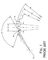
- Figure 1 illustrates a symmetrical tooth space form for an ISO-606 compliant sprocket. The tooth space has a continuous fillet or root radius Ri from one tooth flank (i.e., side) to the adjacent tooth flank. A chain with a link pitch P has rollers of diameter D1 in contact with the tooth spaces. The ISO sprocket has a chordal pitch also of length P, a root diameter D2, and Z number of teeth. The tooth flank radius Rf, pitch circle diameter PD, tip diameter OD, tooth angle A (equal to 360°/Z), and roller seating angle α further define the ISO-606 compliant sprocket. The maximum and minimum roller seating angle α is defined as:
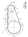
- With reference to Figure 2, an exemplary ISO-606 compliant roller chain drive system 10 rotates in a clockwise direction as shown by arrow 11. The chain drive system 10 includes a drive sprocket 12, a driven sprocket 14 and a roller chain 16 having a number of rollers 18. The sprockets 12, 14, and chain 16 each generally comply with the ISO-606 standard.
- The roller chain 16 engages and wraps about sprockets 12 and 14 and has two spans extending between the sprockets, slack strand 20 and taut strand 22. The roller chain 16 is under tension as shown by arrows 24. The taut strand 22 may be guided from the driven sprocket 14 to the drive sprocket 12 with a chain guide 26. A first roller 28 is shown at the onset of meshing at a 12 o'clock position on the drive sprocket 12. A second roller 30 is adjacent to the first roller 28 and is the next roller to mesh with the drive sprocket 12.
- Chain drive systems have several components of undesirable noise. A major source of roller chain drive noise is the sound generated as a roller leaves the span and collides with the sprocket during meshing. The resultant impact noise is repeated with a frequency generally equal to that of the frequency of the chain meshing with the sprocket. The loudness of the impact noise is a function of the impact energy (EA) that must be absorbed during the meshing process. The impact energy absorbed is related to engine speed, chain mass, and the impact velocity between the chain and the sprocket at the onset of meshing. The impact velocity is affected by the chain-sprocket engagement geometry, of which an engaging flank pressure angle γ (Fig. 3) is a factor, where:

- EA = Impact Energy [N·m]
- VA = Roller Impact Velocity [m/s]
- γ = Engaging Flank Pressure Angle
- n = Engine Speed [RPM]
- w = Chain Mass [Kg/m]
- Z = Number of Sprocket Teeth
- A = Tooth Angle (360°/Z)
- α = Roller Seating Angle
- P = Chain Pitch (Chordal Pitch)
-
- The impact energy (EA) equation presumes the chain drive kinematics will conform generally to a quasi-static analytical model and that the roller-sprocket driving contact will occur at a tangent point TP (Fig. 3) of the flank and root radii as the sprocket collects a roller from the span.
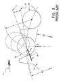
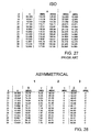
- As shown in Figure 3, the pressure angle γ is defined as the angle between a line A extending from the center of the engaging roller 30 normal to and through the tangent point TP of engaging flank radius Rf and root radius Ri, and a line B connecting the centers of an imaginary roller fully seated on the theoretical pitch diameter PD and the engaging roller 30 when fully seated on the theoretical pitch diameter PD. The roller seating angles α and pressure angles γ listed in Figure 27 are calculated from the equations defined above. It should be appreciated that γ is a minimum when α is a maximum. The exemplary 18-tooth, ISO-606 compliant, sprocket 12 of Figure 3 will have a pressure angle γ in the range of 12.5° to 22.5° as shown in Figure 27.
- Figure 3 also shows the engagement path (phantom rollers) and the meshing contact position of roller 30 (solid) as the drive sprocket 12 rotates in the direction of arrow 11. Figure 3 depicts the theoretical case with chain roller 28 seated on root diameter D2 of a maximum material sprocket with both chain pitch and sprocket chordal pitch equal to theoretical pitch P. For this theoretical case, the noise occurring at the onset of roller engagement has a radial component FIr as a result of roller 30 colliding with the root surface Ri and a tangential component FIt generated as the same roller 30 collides with the engaging tooth flank at point TP as the roller moves into driving contact. It is believed that the radial impact occurs first, with the tangential impact following nearly simultaneously. Roller impact velocity VA is shown to act through, and is substantially normal to, engaging flank tangent point TP with roller 30 in driving contact at point TP.
- The impact energy (EA) equation accounts only for a tangential roller impact during meshing. The actual roller engagement, presumed to have a tangential and radial impact (occurring in any order), would therefore seem to be at variance with the impact energy (EA) equation. The application of this quasi-static model, which is beneficially used as a directional tool, permits an analysis of those features that may be modified to reduce the impact energy that must be absorbed during the tangential roller-sprocket collision at the onset of meshing. The radial collision during meshing, and its effect on noise levels, can be evaluated apart from the impact energy (EA) equation.
- Under actual conditions as a result of feature dimensional tolerances, there will normally be a pitch mismatch between the chain and sprocket, with increased mismatch as the components wear in use. This pitch mismatch serves to move the point of meshing impact, with the radial collision still occurring at the root surface R1 but not necessarily at D2. The tangential collision will normally be in the proximity of point TP, but this contact could take place high up on the engaging side of root radius Ri or even radially outward from point TP on the engaging flank radius Rf as a function of the actual chain-sprocket pitch mismatch.
- Reducing the engaging flank pressure angle γ reduces the meshing noise levels associated with roller chain drives, as predicted by the impact energy (EA) equation set forth above. It is feasible but not recommended to reduce the pressure angle γ while maintaining a symmetrical tooth profile, which could be accomplished by simply increasing the roller seating angle α, effectively decreasing the pressure angle for both flanks. This profile as described requires that a worn chain would, as the roller travels around a sprocket wrap (discussed below), interface with a much steeper incline and the rollers would necessarily ride higher up on the coast flank prior to leaving the wrap.
- Another source of chain drive noise is the broadband mechanical noise generated in part by shaft torsional vibrations and slight dimensional inaccuracies between the chain and the sprockets. Contributing to a greater extent to the broadband mechanical noise level is the intermittent or vibrating contact that occurs between a worn roller chain and sprocket as the rollers travel around the sprocket wrap. In particular, ordinary chain drive system wear comprises sprocket tooth face wear and chain wear. The chain wear is caused by bearing wear in the chain joints and can be characterized as pitch elongation. It is believed that a worn chain meshing with an ISO standard sprocket will have only one roller in driving contact and loaded at a maximum loading condition.
- With reference again to Figure 2, driving contact at maximum loading occurs as a roller enters a drive sprocket wrap 32 at engagement. Engaging roller 28 is shown in driving contact and loaded at a maximum loading condition. The loading on roller 28 is primarily meshing impact loading and the chain tension loading. The next several rollers in the wrap 32 forward of roller 28 share in the chain tension loading, but at a progressively decreasing rate. The loading of roller 28 (and to a lesser extent for the next several rollers in the wrap) serves to maintain the roller in solid or hard contact with the sprocket root surface 34.
- A roller 36 is the last roller in the drive sprocket wrap 32 prior to entering the slack strand 20. Roller 36 is also in hard contact with drive sprocket 12, but at some point higher up (e.g., radially outwardly) on the root surface 34. With the exception of rollers 28 and 36, and the several rollers forward of roller 28 that share the chain tension loading, the remaining rollers in the drive sprocket wrap 32 are not in hard contact with the sprocket root surface 34, and are therefore be free. to vibrate against the sprocket root surfaces as they travel around the wrap, thereby contributing to the generation of unwanted broadband mechanical noise.
- A roller 38 is the last roller in a sprocket wrap 40 of the driven sprocket 14 before entering the taut strand 22. The roller 38 is in driving contact with the sprocket 14. As with the roller 36 in the drive sprocket wrap 32, a roller 42 in the sprocket wrap 40 is in hard contact with a root radius 44 of driven sprocket 14, but generally not at the root diameter.
- It is known that providing pitch line clearance (PLC) between sprocket teeth promotes hard contact between the chain rollers and sprocket in the sprocket wrap as the roller chain wears. The amount of pitch line clearance added to the tooth space defines a length of a short arc. that is centered in the tooth space and forms a segment of the root diameter D2. The root fillet radius Ri is tangent to the flank radius RF and the root diameter arc segment. The tooth profile is still symmetrical, but Ri is no longer a continuous fillet radius from one flank radius to the adjacent flank radius. This has the effect of reducing the broadband mechanical noise component of a chain drive system. However, adding pitch line clearance between sprocket teeth does not reduce chain drive noise caused by the roller-sprocket collision at impact.
- Chordal action, or chordal rise and fall, is another important factor affecting the operating smoothness and noise levels of a chain drive, particularly at high speeds. Chordal action occurs as the chain enters the sprocket from the free span during meshing and it can cause a movement of the free chain in a direction perpendicular to the chain travel but in the same plane as the chain and sprockets. This chain motion resulting from chordal action will contribute an objectionable noise level component to the meshing noise levels, so it is therefore beneficial to reduce chordal action inherent in a roller chain drive.
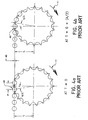
- Figures 4a and 4b illustrate the chordal action for an 18-tooth, ISO-606 compliant, sprocket having a chordal pitch of 9.525 mm. Chordal rise 45 may conventionally be defined as the displacement of the chain centerline as the 'sprocket rotates through an angle A/2, where:
- It is known that a short pitch chain provides reduced chordal action compared to a longer pitch chain having a similar pitch radius. Figures 4a and 4b show only the drive sprocket and assume a driven sprocket (not shown) also having 18-teeth and in phase with the drive sprocket shown. In other words, at T = 0 (Fig. 4a), both sprockets will have a tooth center at the 12 o'clock position. Accordingly, this chain drive arrangement under quasi-static conditions will have a top or taut strand that will move up and down in a uniform manner a distance equal to that of the chordal rise. At T = 0, a roller 46 is at the onset of meshing, with chordal pitch P horizontal and in line with taut strand. At T = 0 + (A/2), (Fig. 4b), roller 46 has moved to the 12 o'clock position.
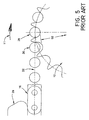
- For many chain drives, the drive and driven sprockets will be of different sizes and will not necessarily be in phase. The chain guide 26 (Fig. 2) has the primary purpose to control chain strand vibration in the free span. The geometry of the guide-chain interface also defines the length of free span chain over which chordal rise and fall is allowed to articulate. Figure 5 is an enlarged view of Figure 2 showing the first roller 28 at the onset of engagement and the second roller 30 as the next roller about to mesh with sprocket 12. In this example, the chain guide 26 controls and guides the engaging portion of the taut strand 22 except for five (5) unsupported or "free" link pitches extending between the chain guide 26 and the engaging roller 28. This length of unsupported link pitches for the engaging portion of taut strand 22 in this example is horizontal when roller 28 is at the 12 o'clock position.
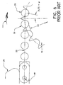
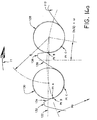
- With reference to Figures 6 and 7, the drive sprocket 12 is rotated in a clockwise direction to advance roller 28 to a new angular position (A/2) + ω, where ω is the added rotation angle as determined by a quasi-static engagement geometry with roller 28 being fully seated and roller 30 is at the instant of sprocket engagement. As shown in Figure 6, roller 28 is considered to be seated and in hard contact with the root surface at D2 at the onset of meshing of roller 30, and a straight line is assumed for the chain span from roller 28 to a chain pin center 48, about which the unsupported or "free" span from pin 48 to engaging roller 30 is considered to rotate.
- As a result of the chordal action, the engaging free span is no longer horizontal to satisfy the roller engaging geometry. This is in contrast to the chain drive as described in Figure 4a in which chordal action causes the taut strand to move uniformly, but in a horizontal path because the drive and driven sprockets have the same number of teeth and the sprocket teeth are in phase. It should be appreciated that the straight line assumption is valid only in a quasi-static model. The amount of movement or deviation from the straight line assumption will be a function of the drive dynamics, the chain control devices and drive and sprocket geometry. The location and chain-interfacing contour of the chain guide 26 will determine the number of free span pitches about which articulation will take place as a result of the chordal rise and fall during the roller meshing process.
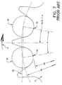
- As best seen in Figure 7, assuming that rollers 28 and 30 are in hard contact with the sprocket root surfaces at D2, the chordal rise is the perpendicular displacement of the center of roller 30 (located on the pitch diameter PD) from the taut span 22 path as it moves from its initial meshing position shown to the position presently occupied by roller 28.
- Accordingly, it is desirable to develop a new and improved roller chain drive system which meets the above-stated needs and overcomes the foregoing disadvantages and others while providing better and more advantageous results.
- In accordance with one aspect of the present invention, a sprocket is disclosed.
- The sprocket includes a first plurality of sprocket teeth each having a first asymmetrical tooth profile which is constructed for providing a tangential contact with a first roller at an onset of the first roller meshing with the sprocket, and a second plurality of sprocket teeth each having a second asymmetrical tooth profile different from the first tooth profile, which is constructed for providing a radial contact with a second roller at an onset of the second roller meshing with the sprocket.
- In accordance with a further aspect of the present invention, a unidirectional roller chain drive system is disclosed comprising a sprocket according to the first aspect of the present invention.
- In accordance with yet another aspect of the present invention, a method of modifying a meshing impact frequency of a roller chain meshing with a sprocket is disclosed. The method includes (a) rotating the sprocket to cause a first roller of the roller chain to tangentially contact an engaging flank of a first sprocket tooth at an onset of the first roller meshing with the first sprocket tooth, and (b) rotating the sprocket to cause a second roller of the roller chain to radially contact a root surface of a second sprocket tooth at an onset of the second roller meshing with the second sprocket tooth.
- One advantage of the present invention is the provision of a roller chain sprocket which incorporates a flank flat on an engaging tooth surface which facilitates altering a meshing contact from a first tooth profile to a second tooth profile.
- Another advahtage of the present invention is the provision of a roller chain sprocket which incorporates a flank flat on an engaging tooth surface which effects a time delay between an initial roller-to first sprocket tooth profile contact and an initial roller-to-second sprocket tooth profile contact.
- Another advantage of the present invention is the provision of a roller chain sprocket which incorporates a flank flat on an engaging tooth surface of a first tooth profile which facilitates phasing a frequency of initial roller-to-engaging flank contacts of the first tooth profile relative to initial roller-to-engaging flank contacts of a second tooth profile to alter the rhythm of the initial roller-to-first engaging flank and the roller-to-second engaging flank contacts.
- Another advantage of the present invention is the provision of a roller chain sprocket which incorporates added pitch mismatch between the sprocket and roller chain to facilitate a "staged" roller-to-sprocket impact.
- Still another advantage of the present invention is the provision of a roller chain sprocket which incorporates an inclined root surface on an engaging flank, a coast flank, or both an engaging flank and a coast flank to provide tooth space clearance.
- Yet another advantage of the present invention is the provision of a roller chain sprocket which minimizes impact noise generated by a roller-sprocket collision during meshing.
- A further advantage of the present invention is the provision of a roller chain sprocket which minimizes broadband mechanical noise generated by unloaded rollers in a sprocket wrap.
- A still further advantage of the present invention is the provision of a roller chain sprocket which provides a "staged" roller impact wherein a tangential impact occurs first followed by a radial impact at full mesh.
- Yet a further advantage of the present invention is the provision of a roller chain sprocket which spreads roller engagement over a significant time interval to provide for a more gradual load transfer, thereby minimizing roller-sprocket impact and the inherent noise generated therefrom.
- Yet a further advantage of the present invention is the provision of a roller chain sprocket having two sets of sprocket teeth incorporating different tooth profiles which cooperate to reduce chain drive system noise levels below a noise level which either tooth profile used alone would produce.
- Further advantages of the present invention will become apparent to those of ordinary skill in the art upon reading and understanding the following detailed description of the preferred embodiments.
- The invention may take form in various components and arrangements of components, and in various steps and arrangements of steps. The drawings are only for purposes of illustrating a preferred embodiment and are not to be construed as limiting the invention.
- Figure 1 illustrates a symmetrical tooth space form for a ISO-606 compliant roller chain sprocket;
- Figure 2 is an exemplary roller chain drive system having a ISO-606 compliant drive sprocket, driven sprocket, and roller chain;
- Figure 3 shows an engagement path (phantom) and a roller (solid) in a driving position as a ISO-606 compliant drive sprocket rotates in a clockwise direction;
- Figure 4a shows a roller at the onset of meshing with an exemplary 18-tooth sprocket;
- Figure 4b shows the drive sprocket of Figure 4a rotated in a clockwise direction until the roller is at a 12 o'clock position;
- Figure 5 is an enlarged view of the drive sprocket of Figure 2 with a roller fully seated in a tooth space and a second roller about to mesh with the drive sprocket;
- Figure 6 shows the drive sprocket of Figure 5 rotated in a clockwise direction until the second roller initially contacts the drive sprocket;
- Figure 7 is an enlarged view of Figure 6 showing that the second roller initially contacts a root surface (i.e., radial impact) of the drive sprocket, under theoretical conditions;
- Figure 8 illustrates a roller chain drive system having a roller chain drive sprocket and driven sprocket which incorporate the features of the present invention therein;
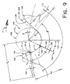
- Figure 9 illustrates the roller chain drive sprocket of Figure 8 with an asymmetrical tooth space form in accordance with one embodiment of the present invention;
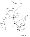
- Figure 10 is an enlarged view of the asymmetrical tooth space form of Figure 9 showing a roller in two-point contact with the sprocket;
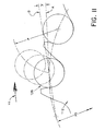
- Figure 11 shows an engagement path (phantom) and the instant of full mesh (solid) of a roller as the drive sprocket of Figure 8 rotates in a clockwise direction;
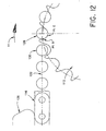
- Figure 12 is an enlarged view of the drive sprocket of Figure 8 with a first roller fully seated in a tooth space and a second roller as the next roller to be collected from a taut span of the roller chain;
- Figure 13 shows the drive sprocket of Figure 12 rotated in a clockwise direction until the second roller initially contacts the drive sprocket;
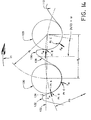
- Figure 14 is an enlarged view of Figure 13 showing the first roller in two-point contact and second roller at initial tangential contact with the drive sprocket;
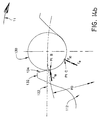
- Figure 14a illustrates the progression of the first and second rollers as the drive sprocket of Figure 14 is rotated in a clockwise direction;
- Figure 14b is an enlarged view of the drive sprocket of Figure 14 rotated in a clockwise direction to advance the second roller to the instant of full mesh at a 12 o'clock position;
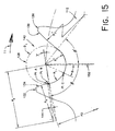
- Figure 15 illustrates a roller chain drive sprocket with an asymmetrical tooth space form in accordance with another embodiment of the present invention;
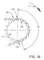
- Figure 16 is an enlarged partial view of Figure 8, showing the contact progression as the rollers travel around the drive sprocket wrap;
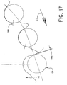
- Figure 17 is an enlarged view of a roller exiting a sprocket wrap of the sprocket of Figure 16;
- Figure 18 illustrates a roller chain sprocket with an asymmetrical tooth space form in accordance with another embodiment of the present invention;
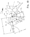
- Figure 19 illustrates a roller chain sprocket with an asymmetrical tooth space form in accordance with a further embodiment of the present invention;
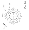
- Figure 20 is a side view of an exemplary random-engagement roller chain sprocket which incorporates the features of the present invention therein;
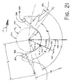
- Figure 21 is an enlarged view of the sprocket of Figure 20 showing an asymmetrical tooth space form which incorporates engaging flank relief and tooth space clearance in accordance with the present invention;
- Figure 21a is an enlarged view of the sprocket of Figure 21 showing an inclined root surface thereof which provides flank relief and tooth space clearance;
- Figure 22 is another embodiment of the inclined root surface of Figure 21a which only provides flank relief;
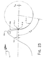
- Figure 23 illustrates the asymmetrical tooth space form of Figure 9 overlaid with the asymmetrical tooth space form of Figure 21;
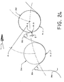
- Figure 24 illustrates the meshing progression of a first roller and the meshing of a second adjacent roller with the sprocket of Figure 20 as the sprocket is rotated in a clockwise direction;
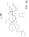
- Figure 25 illustrates the sprocket of Figure 20 with a first roller in two-point contact, a second roller at initial tangential contact, and a third roller about to mesh with the drive sprocket;
- Figure 26 illustrates the sprocket of Figure 25 rotated in a clockwise direction until the instant of initial engagement of the third roller at a root surface of the sprocket;
- Figure 27 is a table listing roller seating angles α and pressure angles γ for a number of different ISO-606 complaint sprocket sizes; and
- Figure 28 is a table listing the maximum Beta (β) angles and the corresponding pressure angles (γ) for three different asymmetrical tooth space profiles (1-3) of varying sprocket sizes.
-
- With reference now to Figure 8, a roller chain drive system 110 includes a drive sprocket 112 and a driven sprocket 114 which incorporate the features of the present invention therein. The roller chain drive system 110 further includes a roller chain 116 having a number of rollers 118 which engage and wrap about sprockets 112, 114. The roller chain rotates in a clockwise direction as shown by arrow 11.
- The roller chain 116 has two spans extending between the sprockets, slack strand 120 and taut strand 122. The roller chain 116 is under tension as shown by arrows 124. A central portion of the taut strand 122 may be guided from the driven sprocket 114 to the drive sprocket 112 with a chain guide 126. A first roller 128 is shown fully seated at a 12 o'clock position on the drive sprocket 112. A second roller 130 is adjacent to the first roller 128 and is about to mesh with the drive sprocket 112.
- To facilitate a description of the asymmetrical tooth profiles of the present invention, reference will be made only to the drive sprocket 112. However, the asymmetrical tooth profiles of the present invention can be equally applied to the driven sprocket 114, as well as to other types of sprockets such as idler sprockets and sprockets associated with counter rotating balance shafts.
- Referring now to Figures 9 and 10, the sprocket 112 includes a first tooth 132 having an engaging flank 134, and a second tooth 136 having a coast or disengaging flank 138. The engaging flank 134 and coast flank 138 cooperate to define a tooth space 140 which receives the engaging roller 128 (shown in phantom). The engaging roller 128 has a roller diameter D1, and is shown fully seated in two-point contact within the tooth space 140 as described further below. More particularly, the engaging roller 128, when fully seated in the tooth space, contacts two lines B and C that extend axially along each sprocket tooth surface or face (i.e., in a direction orthogonal to the plane of the drawings). However, to facilitate a description thereof, the lines A, B, and C are hereafter shown and referred to as contact points within the tooth space.
- The engaging flank 134 has a radius Rf which is tangent to a radially outer end of a flank flat 144. The asymmetrical engaging flank radius Rf is smaller than the RfISO radius specified by the ISO-606 standard. However, the magnitude of the asymmetrical engaging flank radius Rf should be as large as possible while still satisfying the roller meshing (engaging) and disengaging geometry. The location of the flank flat 144 is defined by an angle β, with the flat orientation being normal or perpendicular to a line that passes through Point B and the center of roller 128 when the roller is contacting the sprocket at Points B and C. The length of the flank flat, which extends radially outward from Point B, affects a time delay between an initial tangential impact between sprocket 112 and roller 128 at a first contact Point A along the flank flat 144, and a subsequent radial impact at Point C. It is believed that the roller stays in contact with the flank flat from its initial tangential contact at Point A until the roller moves to a fully engaged two-point contact position at Points B and C. The pressure angle γ, the amount of pitch mismatch between the chain and the sprocket, and the length of the flank flat can be varied to achieve a desired initial roller contact Point A at the onset of roller-sprocket meshing.
- It should be appreciated that flank (tangential) contact always occurs first, with radial contact then occurring always at Point C regardless of chain pitch length. In contrast, with known tooth space forms (e.g., ISO-606 compliant and asymmetrical) incorporating single-point contact (e.g. single line contact), an engaging roller must move to a driving position after making radial contact. The pressure angles γ therefore assume that the engaging roller will contact at the flank radius/root radius tangent point. Thus, the meshing contact location of the known single point/line tooth space forms is pitch "sensitive" to determine where the radial impact as well as tangential impact will occur.
- The engaging flank roller seating angle β (Fig. 9) and a disengaging flank roller seating angle β' replace the ISO-606 roller seating angle α (ISO profile shown in phantom). The pressure angle γ is a function of the engaging flank roller seating angle β. That is, as β increases, γ decreases. A minimum asymmetrical pressure angle can be determined from the following equation, where:
- Therefore, an asymmetrical pressure angle γmin = 0 when βmax = (αmax /2 + γISO min) as illustrated in Figure 28. Figure 28 lists the maximum Beta (β) angles and the corresponding pressure angles (γ) for several sprocket sizes of three different asymmetrical tooth space profiles (1-3). It should be appreciated that reducing the engaging flank pressure angle γ reduces the tangential impact force component FIA (Fig. 14) and thus the tangential impact noise contribution to the overall noise level at the onset of engagement.
- That is, the impact force FIA is a function of the impact velocity which in turn is related to pressure angle γ. As pressure angle γ is reduced, it provides a corresponding reduction in the impact velocity between the chain and the sprocket at the onset of meshing. A minimum pressure angle γ also facilitates a greater separation or distance between tangential contact points A and B to further increase or maximize engagement "staging". In the preferred embodiment, the engaging flank pressure angle γ is in the range of about -2.0° to about +5° to optimize the staged impact between the roller and the sprocket.
- In the embodiment being described, roller seating angle β is greater than ISO αmax/2 at a maximum material condition and β can be adjusted until a desired engaging flank pressure angle γ is achieved. For instance, the roller seating angle β of Figure 9 provides a pressure angle γ that is less than zero, or a negative value. The negative pressure angle γ is best seen in Figure 11, as contrasted with the ISO-606 compliant tooth profile of Figure 3 with a positive pressure angle γ. It is believed that a small negative pressure angle for the theoretical chain/sprocket interface beneficially provides a pressure angle γ closer to zero (0) for a "nominal" system or for a system with wear. However, the engaging flank roller seating angle β may be beneficially adjusted so as to provide any engaging flank pressure angle γ having a value less than the minimum ISO-606 pressure angle.
- Referring again to Figures 9 and 10, a first root radius Ri is tangent to a radially inner end of the flank flat 144, and tangent to a radially outer end of an inclined root surface 146. As best seen in Figure 10, a maximum root radius Ri must be equal to, or less than, a minimum roller radius 0.5D1 to facilitate the fully engaged two-point/line contact at Points B and C. Accordingly, this will define a small clearance between Ri at the engaging flank 134 and the roller 128 at the two-point/line engagement. The flank flat 144 and the inclined root surface 146 necessarily extend inside Points B and C respectively to facilitate the two-point/line roller contact at engagement as well as the required clearance Ri to the roller 128. A second root radius Ri' is tangent to a radially inner end of the inclined root surface 146 at line 150. The coast flank has a radius Rf' with its arc center defined by disengaging side roller seating angle β'. The radius Rf' can have a value in the ISO-606 range.
- The inclined root surface 146 is a flat surface having a finite length which defines a tooth space clearance (TSC). The tooth space clearance compensates for chain pitch elongation or chain wear by accommodating a specified degree of chain pitch elongation ΔP. In other words, the tooth space clearance TSC enables rollers of a worn chain to be maintained in hard contact with the inclined root surface of the sprocket teeth. In addition, the inclined root surface 146 facilitates reducing the radial reaction force thereby reducing the roller radial impact noise contribution to the overall noise level.
- The inclined root surface 146 may be inclined at any angle necessary to satisfy a specific chain drive geometry and chain pitch elongation. As shown in Figure 9, the inclined root surface angle is measured from a line 152 passing through the center of roller 128 and the sprocket center to a second line 154 which also passes through the center of roller 128 and Point C. The inclined root surface 146 is normal to the line 154, and the inclined root surface extends radially inward to line 150 where it is tangent to Ri'. In the embodiment being described, the inclined root surface angle is preferably in the range of about 20° to about 35°.
- Figure 12 is an enlarged view of Figure 8 showing the first roller 128 at full engagement in two-point/line contact across the thickness or width of the sprocket tooth profile, and the second roller 130 as the next roller about to mesh with sprocket 112. As with the ISO-606 compliant drive system 10, the chain guide 126 controls and guides a central portion of the taut strand 122 except for five unsupported link pitches extending between the chain guide 126 and the engaging roller 128 (and except for the unsupported link pitches extending between the driven sprocket and the chain guide). The taut strand 122 is horizontal when roller 128 is at the 12 o'clock position.
- Figure 13 shows the drive sprocket 112 rotated in a clockwise direction (A/2) + ω, as determined by the instant of sprocket engagement by roller 130. A straight line is assumed for the chain span from roller 128 to a chain pin center 156, about which the unsupported span from pin center 156 to engaging roller 130 is considered to rotate. It should be appreciated that the straight line assumption is valid only in a quasi-static model. The amount of movement (or deviation from the straight line assumption) previously mentioned will be a function of the drive dynamics as well as the drive and sprocket geometry.
- The sprocket contact at the onset of mesh for roller 130 occurs earlier than for the ISO-606 counterpart, thereby reducing the amount of chordal rise and, just as importantly, allows the initial contact to beneficially occur at a desired pressure angle γ on the engaging flank at Point A. Furthermore, the radial sprocket contact for roller 130, with its contribution to the overall noise level, does not occur until the sprocket rotation places roller 130 at the 12 o'clock position. This is referred to as staged engagement.
- Figure 14, an enlarged view of Figure 13, more clearly shows the onset of meshing for roller 130. Just prior to the onset of mesh, roller 128 is assumed to carry the entire taut strand load FTB + F, which load is shown as force vector arrows. Actually, the arrows represent reaction forces to the taut strand chain force. At the instant of mesh for roller 130, a tangential impact occurs as shown by impact force vector FIA. The tangential impact is not the same as the taut strand chain loading. In particular, impact loading or impact force is related to the impact velocity VA. It is known that impact occurs during a collision between two bodies, resulting in relatively large forces over a comparatively short interval of time. A radial impact force vector FIC is shown only as an outline in that the radial impact does not occur until the sprocket has rotated sufficiently to place roller 130 at a 12 o'clock position.
- Figure 14a shows the same roller positions (solid) for rollers 128 and 130 as shown in Figure 14, but in addition, shows the roller positions (in phantom) relative to the sprocket profile once roller 130 reaches its two-point/line mesh at the 12 o'clock position. As a result of the pitch mismatch between the chain and sprocket, roller 128 must move to a new position. In particular, as roller 130 moves from initial contact to full mesh, roller 128 progresses forward in its tooth space. Small clearances in the chain joints, however, reduce the amount of forward progression required for roller 128. Also occurring at the onset of meshing is the beginning of the taut strand load transfer from roller 128 to roller 130.
- The asymmetrical profile provides for the previously described "staged" meshing. In particular, referring again to Figure 14, the Point A tangential contact occurs at the onset of mesh, with its related impact force FIA. The roller 130 is believed to stay in hard contact with the engaging flank 134 as the sprocket rotation moves the roller into full mesh with its resulting radial contact at Point C. The radial impact force FIC (force vector shown as an outline) does not occur until the sprocket has rotated sufficiently to bring roller 130 into radial contact at Point C.
- Figure 14b is an enlarged view of Figure 14, except that sprocket 112 has been rotated to advance roller 130 to the instant of full mesh at the 12 o'clock position. At this instant of full mesh, the radial impact force FIC occurs and the taut strand load transfer is considered to be complete. At the instant of the radial collision by roller 130 at Point C, with its resultant radial impact force FIC, the tangential impact force of FIA has already occurred and is no longer a factor. The time delay ("staged" engagement) between the tangential and radial roller-sprocket collisions effectively spreads the impact energy that must be absorbed during the meshing process over a greater time interval, thereby reducing its contribution to the generated noise level at mesh frequency. Additionally, it is believed that the present asymmetrical sprocket tooth profile beneficially permits a more gradual taut strand load transfer from a fully engaged roller 128 to a meshing roller 130 as the meshing roller 130 moves from its Point A initial mesh to its full two-point mesh position.
- Referring again to Figure 14, the chordal rise (and fall) with the present asymmetrical profile is the perpendicular displacement of the center of roller 130 from the taut strand 122 path as it moves from its initial meshing contact Point A to the mesh position presently occupied by roller 128. It is believed that roller 130 will stay in hard contact with the engaging flank 134 as the roller moves from initial tangential contact to full mesh, and accordingly, the chordal rise is reduced as the distance between Points A and B is increased. As shown in Figure 14, chain pitch PC is beneficially greater than sprocket 112 chordal pitch PS.
- Referring now to Figure 15, the length of the inclined root surface 146 (Fig. 10) may be reduced to zero (0), thereby eliminating the inclined roof surface 146 and permitting root radius Ri' to be tangent to the root surface and the roller 128 at Point C. That is, Ri' is tangent to a short flat at Point C, and the flat is tangent to Ri. If the inclined root surface 146 is eliminated, the engaging flank pressure angle γ would generally be in the range of some positive value to zero, but normally not less than zero. The reason is that a negative γ requires chordal pitch reduction so that the roller can exit the sprocket wrap 60 (Fig. 16) without interfering with Rf.
- Figure 16 shows the roller contact to the sprocket 112 profile for all the rollers in the wrap 60. Roller 128 is in full two-point mesh as shown. Line 160 shows the contact point for each of the rollers, as well as the contact progression as the rollers travel around the wrap. The inherent pitch mismatch between the sprocket and roller chain causes the rollers to climb up the coast side flank as the rollers progress around the sprocket wrap. With the addition of appreciable chordal pitch reduction, the extent to which the rollers climb up the coast side flank in increased.
- It is important to note that chordal pitch reduction is required when the pressure angle γ has a negative value. Otherwise, as shown in Figures 16 and 17, roller 136 would interfere with the engaging flank (with a maximum material sprocket and a theoretical pitch [shortest] chain) as it exits the wrap 60 back into the span. That is, chordal pitch reduction permits the roller 136 to exit the wrap 60 with a clearance 163 for the engaging flank. Also, the reduced chordal pitch assists the staged mesh as previously mentioned. Figure 17, showing the roller contact progression in the wrap 60, serves also to show why the shallow β' angle and tooth space clearance TSC helps maintain "hard" roller-sprocket contact for the rollers in the wrap.
- In addition, the disengaging flank roller seating angle β' (Fig. 9) may be adjusted to have a maximum value which is equal to αmin/2 or even less. This reduced roller seating angle β' promotes faster separation when the roller leaves the sprocket and enters the span. This reduced angle β' also allows for the roller in a worn chain to ride up the coast flank surface to a less severe angle as the roller moves around the sprocket in the wrap. Accordingly, chordal pitch reduction, if used in this embodiment, should be a small value.
- It is contemplated that the above-described asymmetrical tooth profile features can be altered without substantially deviating from the chain and sprocket meshing kinematics that produce the noise reduction advantages of the present invention. For example, the engaging asymmetrical flank profile could be approximated by an involute form, and the disengaging asymmetrical flank profile could be approximated by a different involute form. Slight changes to the asymmetrical tooth profiles may be for manufacturing and/or quality control reasons, or simply to improve part dimensioning. These changes are within the scope of the invention as disclosed herein.
- In a further embodiment, the engaging flank inclined root surface 146 (Fig. 9) may be replaced with a coast flank inclined root surface 164 as shown in Figure 18. The coast flank inclined root surface 164 provides tooth space clearance (TSC) in the same manner as described above with regard to the inclined root surface 146. In addition, the engaging flank inclined root surface 164 beneficially moves the roller to a preferred radially outward position as the chain wears.
- Alternatively, the coast flank inclined root surface 164 may be included with the engaging flank inclined root surface 146 as shown in Figure 19. The engaging flank and coast flank inclined root surfaces 146, 164 cooperate to provide tooth space clearance (TSC) in the same manner as previously described.
- Referring now to Figure 20, any one of the above-described asymmetrical tooth profile embodiments of Figures 9, 15, 18, and 19 may be incorporated into a random-engagement roller chain sprocket 300. The sprocket 300 is shown as an 18-tooth sprocket. However, the sprocket 300 may have more or less teeth, as desired. The sprocket 300 includes a first group of arbitrarily positioned sprocket teeth 302 each having a profile which incorporates the flank flat 144 shown in Figures 9, 15, 18 and 19. Further, the sprocket teeth 302 can incorporate none, one or both inclined root surfaces 146, 164 as shown in Figs. 9, 15, 18 and 19. The remaining sprocket teeth 304 (sprocket teeth 1, 3, 4, 9, 13, 14, and 16) are randomly positioned around the sprocket and incorporate a tooth profile different from that of the first group of sprocket teeth 302. As described further below, the first and second groups of sprocket teeth 302, 304 cooperate to reduce chain drive system noise levels below a noise level which either tooth profile used alone would produce.
- Figure 21 illustrates an exemplary tooth profile for one of the sprocket teeth 304. An engaging flank 306 and a coast or disengaging flank 308 of an adjacent tooth cooperate to define a tooth space 310 which receives an engaging roller 314 (shown in phantom). The engaging roller 314 has a roller diameter D1 and is shown fully seated with single point (line) contact within the tooth space 310. As best seen in Figure 21a, the engaging roller 314 does not contact the engaging flank 306 at the onset of meshing, moving instead directly from the span to full-mesh root contact on a inclined root surface 316 at a contact point C' located radially outward of contact point C in a direction toward the engaging flank 306. Contact point C' is a roller/tooth contact line that extends axially along each sprocket tooth surface (i.e., in a direction orthogonal to the plane of the drawings).
- As shown in Figures 21 and 21a, the first or engaging root radius Ri is tangent to inclined root surface 316 at line 319, and also tangent to Rf as defined by angle β. Angle β has no functional requirements specific to the onset of roller meshing since roller/flank contact will not take place with tooth profile 304. It should be noted that Ri can be equal to the ISO-606 root radius for tooth profile 304.
- The length of the inclined root surface from point C to its radially outer end at line 319 is determined by the amount of flank offset required to ensure that the roller will not have engaging flank contact for any expected chain pitch elongation (wear) throughout its design life. In the preferred embodiment, the flank offset 323 is in the range of about 0.025 to about 0.13 mm. The flank offset 323 is an extension of inclined root surface 316 which provides tooth space clearance (TSC) in the same manner described above with regard to inclined root surface 146.
- As previously mentioned, tooth space clearance compensates for chain pitch elongation or chain wear by accommodating a specified degree of chain pitch elongation. In other words, the tooth space clearance TSC enables rollers of a worn chain to be maintained in hard contact with the inclined root surface of the sprocket teeth. In addition, the inclined root surface 316 facilitates reducing the radial reaction force thereby reducing the roller radial impact noise contribution to the overall noise level.
- The inclined root surface 316 may be inclined at any angle necessary to satisfy a specific chain drive geometry and chain pitch elongation. The inclined root surface angle is measured from a line 320 passing through the center of roller 314 and the sprocket center to a second line 322 which also passes through the center of roller 314 and through contact point C. The inclined root surface 316 is normal to the line 322, and the inclined root surface extends radially inward to line 318 where it is tangent to Ri'. In the embodiment being described, the inclined root surface angle is preferably in the range of about 20° to about 35°.
- Figure 22 shows another embodiment of the tooth profile 304 where no tooth space clearance TSC is provided. That is, the flat surface portion of the inclined root surface from line 318 to line 322 is not present. Thus, the profile of the tooth 304 from point C to the outside or tip diameter at the disengaging side of the tooth space is substantially identical to the tooth profile shown in Figure 15. The remaining flat surface portion 323 of the inclined root surface 316 from line 322 to line 329 functions only to provide the engaging flank offset as described above.
- It should be appreciated that the portion of the engaging flank inclined root surface from line 318 to line 322 may be replaced with a coast flank inclined root surface 164 as in Figure 18. That is, the tooth profile 304 may be substantially identical to the sprocket 112 shown in Figure 18 from contact point C to the outer diameter of the coast flank 138. The coast flank inclined root surface 164 provides tooth space clearance (TSC) in the same manner as the inclined root surface 316. In addition, the coast flank inclined root surface beneficially moves the roller to a preferred radially outward position as the chain wears. Alternatively, the coast flank inclined root surface 164 may be included with the engaging flank inclined root surface 316 as in Figure 19. Thus, the tooth profile 304 may also be substantially identical to the sprocket 112 shown in Figure 19 from contact point C to the outer diameter of the coast flank 138.
- Pitch mismatch is inherent in a chain/sprocket interface except at one condition - the theoretical condition which is defined as a chain at its shortest pitch (shortest being theoretical pitch) and a maximum material sprocket. This theoretical condition therefore defines one limit (zero, or no pitch mismatch) of the tolerance range of the pitch mismatch relationship of chain and sprocket. The other limit is defined when a longest "as built" chain is used with a sprocket at minimum material conditions - or in other words, a sprocket having a minimum profile. This limit produces the greatest amount of pitch mismatch. The pitch mismatch range is therefore determined by the part feature tolerances.
- Additional pitch mismatch may be introduced to facilitate a greater time delay, or "staged" meshing, between the initial tangential contact at point A and the full seated contact at points B and C for tooth profile 302. It should be appreciated that staged contact for profile 302 is enhanced due to the flank flat 144 which causes initial contact to occur higher up on the engaging flank. This will result in reduced mesh frequency noise levels because the point and rhythm of the initial roller-to-sprocket contacts are altered for each tooth profile 302, 304 since profile 304 does not have a tangential contact.
- The sprocket chordal pitch is necessarily shorter than the chain pitch to facilitate the "staged" roller-tooth contact. In addition, chordal pitch reduction also provides roller-to-flank clearance as the roller exits the sprocket wrap back into the strand. Added chordal pitch reduction, when used, is preferably in the range of about 0.005 to about 0.030 mm.
- The staged roller contact for tooth profile 302 may be further assisted by providing a sprocket tooth pressure angle γ that is substantially less than the ISO-606 standard. Pressure angles γ equal to or very close to zero (0), or even negative pressure angles, are contemplated.
- Figure 23 illustrates the tooth profile 304 overlaid with the tooth profile 302. An engaging roller is shown at the onset of initial tangential contact at point A along the engaging flank of the tooth profile 302. The engaging roller will maintain contact with the engaging flank until it is at full mesh and seated at points B and C as previously described with reference to Figure 9. The tooth profile 304 is overlaid on the tooth profile 302 to show that an engaging roller only has radial contact on the inclined root surface of the tooth profile 304 (see Figs. 21a and 22) and does not have tangential contact with the tooth profile 304.
- The pressure angle γ for tooth profile 304 has no functional purpose during the onset of roller meshing since the roller does not contact the engaging flank. The pressure angle γ302 for the tooth profile 302 is shown as a negative value. Thus γmin may be a small negative value, and γmax may be a positive value equal to some value less than the ISO-606 minimum pressure angle γ. As a result, initial roller-to-sprocket contact for tooth profile 302 of sprocket 300 (Fig. 20) occurs at point A followed by full engagement contact at points B and C. The sprocket 300 may, or may not incorporate additional chordal pitch reduction, and may, or may not incorporate tooth space clearance (TSC), as described above.
- Figure 24 shows the engagement path of an additional roller 342 from initial contact at point A (phantom) to fully-seated, two-point contact (solid) in a sprocket tooth 302, and an engagement path of the roller 314 engaging an adjacent sprocket tooth 304 of the random engagement sprocket 300. At the onset of meshing for roller 314, a small portion of the chain load transfer takes place with tooth 304 picking up a share of the loading. However, tooth 302 continues to carry a larger portion of the chain loading until an engaging roller meshes with another tooth 304 with its attendant flank contact. The reference 1 in Figure 24 indicates the amount of "staging" for the tooth 302 from the initial contact at point A to the full mesh contact at points B and C.
- Figures 25 and 26 illustrate the meshing delay between the tooth profiles 302, 304. In particular, as shown in Figure 25, the sprocket 300 has a further roller 344 fully-seated in two-point contact with a sprocket tooth incorporating the tooth profile 302. The roller 342 is shown at the instant of initial tangential contact at point A of a second sprocket tooth also incorporating the tooth profile 302. The roller 314 is the next roller in the span and will mesh with a sprocket tooth incorporating the tooth profile 304. The sprocket 300 must rotate through an angle τ for roller 342 to move from its initial contact position at point A to full mesh, seated in two-point contact with the tooth profile 302 at a 12 o'clock position.
- With reference to Figure 26, the sprocket 300 of Figure 25 is shown rotated in a clockwise direction until roller 314 is at the onset of meshing with the tooth profile 304. The sprocket 300 must now rotate through a smaller angle K to have roller 314 seated at the 12 o'clock position. Thus, the sprocket 300 must rotate through an additional angle T-K for an engaging roller to be fully seated in the tooth profile 302.
- Referring again to Figure 20, the two sets of tooth profiles 302, 304 are arranged in a random pattern in order to modify the meshing impact frequency by altering the point and rhythm of initial roller-to-sprocket contact. However, the two sets of tooth profiles 302, 304 could be arranged in many different random patterns. Further, it is also contemplated that the two sets of tooth profiles 302, 304 could be arranged in many regular patterns that would work equally as well. In all cases, the arrangement of two sets of different tooth profiles on a sprocket provides a means for breaking up the mesh frequency impact noise normally associated with and induced by a full complement of substantially identically shaped sprocket teeth. The mesh frequency noise reduction is achieved by altering the point and rhythm of initial roller-to-sprocket contact.
- The crankshaft sprocket, generally the smallest sprocket in the chain drive, is usually the major noise contributor. The typically larger driven camshaft sprocket, however, will also contribute to the generated noise levels, but generally to a lesser extent than the crankshaft sprocket. However, the driven sprocket, particularly if it is nearly the same size or smaller than the driving sprocket, may be the prime noise generator, as in the case with balance shaft sprockets and pump sprockets. Thus, the features of the present invention may also be used advantageously with camshaft or driven sprockets as well.
- It should be appreciated that the tooth profile features of Figures 20-26 can be altered slightly without substantially deviating from the chain and sprocket meshing kinematics that produce the noise reduction advantages of the present invention. For example, the engaging asymmetrical flank profile could be approximated by an involute form, and the disengaging asymmetrical flank profile could be approximated by a different involute form. Slight changes to the profile may be done for manufacturing and/or quality control reasons - or simply to improve part dimensioning.
- The invention has been described with reference to the preferred embodiments. Obviously, modifications will occur to others upon a reading and understanding of this specification and this invention is intended to include same insofar as they come within the scope of the appended claims.
Claims (14)
- A sprocket comprising:a first plurality of sprocket teeth each having a first asymmetrical tooth profile including means for providing a tangential contact with a first roller at an onset of the first roller meshing with the sprocket; anda second plurality of sprocket teeth each having a second asymmetrical tooth profile different from the first tooth profile including means for providing a radial contact with a second roller at an onset of the second roller meshing with the sprocket.
- The sprocket of claim 1 wherein:the first means includes a first engaging flank, a first engaging root, and a first flat positioned between the first engaging flank and the first engaging root, the first roller initially contacting the first flat at the onset of the first roller meshing with the sprocket; andthe second means includes a second engaging flank, a second engaging root, and a second flat tangent to the second engaging root remote from the second engaging flank, the second roller initially contacting the second flat at the onset of meshing between the second roller and the sprocket.
- The sprocket of claim 2, wherein the first plurality of sprocket teeth are arbitrarily positioned relative to the second plurality of sprocket teeth.
- The sprocket of claim 2, wherein the second flat includes a first portion and a second portion, the first portion providing a flank offset and the second portion providing a tooth space clearance.
- The sprocket of claim 2, wherein the second plurality of sprocket teeth include a disengaging flank and a third flat positioned along the disengaging flank for providing a tooth space clearance.
- The sprocket of claim 2, wherein the first plurality of sprocket teeth each include a third flat tangent to the first engaging root remote from the first engaging flank for providing a tooth space clearance.
- The sprocket of claim 2, wherein the first plurality of sprocket teeth include a disengaging flank and a third flat positioned along the disengaging flank for providing a tooth space clearance.
- The sprocket of claim 2, wherein the first roller contacts the sprocket at two points along the first asymmetrical tooth profile in a full mesh position.
- The sprocket of claim 2, wherein a radius of the first engaging root is less than a radius of the first roller.
- A unidirectional roller chain drive system including a first sprocket, a second sprocket, and a roller chain having rollers in engaging contact with the first and second sprockets, wherein at least one of the first and second sprockets is characterised by the sprocket according to claim 1.
- A method of modifying a meshing impact frequency of a roller chain meshing with a sprocket, comprising:(a) rotating the sprocket to cause a first roller of the roller chain to tangentially contact an engaging flank of a first sprocket tooth at an onset of the first roller meshing with the first sprocket tooth; and(b) rotating the sprocket to cause a second roller of the roller chain to radially contact a root surface of a second sprocket tooth at an onset of the second roller meshing with the second sprocket tooth.
- The method of claim 11, wherein step (a) includes the step of:rotating the sprocket to cause the first roller of the roller chain to contact a flank flat at an onset of the first roller meshing with the first sprocket tooth.
- The method of claim 11, wherein step (b) includes the step of:rotating the sprocket to cause the second roller of the roller chain to contact an inclined flat at an onset of the second roller meshing with the second sprocket tooth.
- The method of claim 11, further including the step of:(c) after step (a), further rotating the sprocket to cause the first roller of the roller chain to contact the first sprocket tooth at two other points along the first asymmetrical tooth profile in a full mesh position of the first roller.
Applications Claiming Priority (5)
| Application Number | Priority Date | Filing Date | Title |
|---|---|---|---|
| US3237996P | 1996-12-19 | 1996-12-19 | |
| US32379P | 1996-12-19 | ||
| US992306 | 1997-12-17 | ||
| US08/992,306 US5921879A (en) | 1996-07-25 | 1997-12-17 | Random engagement roller chain sprocket with staged meshing and flank relief to provide improved noise characteristics |
| PCT/US1997/023429 WO1998029673A2 (en) | 1996-12-19 | 1997-12-18 | Random engagement roller chain sprocket |
Publications (3)
| Publication Number | Publication Date |
|---|---|
| EP0944787A2 EP0944787A2 (en) | 1999-09-29 |
| EP0944787A4 EP0944787A4 (en) | 2001-11-14 |
| EP0944787B1 true EP0944787B1 (en) | 2003-05-28 |
Family
ID=26708342
Family Applications (1)
| Application Number | Title | Priority Date | Filing Date |
|---|---|---|---|
| EP97954161A Expired - Lifetime EP0944787B1 (en) | 1996-12-19 | 1997-12-18 | Random engagement roller chain sprocket with staged meshing and flank relief to provide improved noise characteristics |
Country Status (7)
| Country | Link |
|---|---|
| US (2) | US5921879A (en) |
| EP (1) | EP0944787B1 (en) |
| JP (1) | JP4047933B2 (en) |
| BR (1) | BR9714420A (en) |
| CA (1) | CA2275656C (en) |
| DE (1) | DE69722439T2 (en) |
| WO (1) | WO1998029673A2 (en) |
Families Citing this family (48)
| Publication number | Priority date | Publication date | Assignee | Title |
|---|---|---|---|---|
| US6050916A (en) * | 1996-11-22 | 2000-04-18 | Volkswagen Ag | Toothed belt or chain drive arrangement having a tooth with different flank geometry from other teeth |
| US7074147B2 (en) * | 1998-08-25 | 2006-07-11 | Cloyes Gear And Products, Inc. | Roller chain sprocket with symmetric cushion rings |
| US7416500B2 (en) * | 1996-12-19 | 2008-08-26 | Cloyes Gear And Products, Inc. | Random engagement roller chain sprocket and timing chain system including same |
| US6761657B2 (en) * | 1996-12-19 | 2004-07-13 | Cloyes Gear And Products, Inc. | Roller chain sprocket with added chordal pitch reduction |
| CA2246131C (en) * | 1997-10-03 | 2007-06-05 | Borg-Warner Automotive, Inc. | Randomized sprocket for roller chain |
| BR9909667A (en) * | 1998-03-26 | 2000-11-21 | Cloyes Gear & Products Inc | Random chain gear tooth coupling with stepped gear and root relief to provide improved noise characteristics |
| DE69912451T2 (en) * | 1998-08-25 | 2004-05-13 | Cloyes Gear & Products, Inc., Mentor | ROLL CHAIN WHEEL WITH DAMPING RING |
| US6213905B1 (en) | 1999-07-01 | 2001-04-10 | Borgwarner Inc. | Roller chain sprockets oriented to minimize strand length variation |
| US7125356B2 (en) * | 2001-11-06 | 2006-10-24 | Borgwarner Inc. | Tension-reducing random sprocket |
| AU2003299690A1 (en) | 2002-12-19 | 2004-07-22 | Cloyes Gear And Products, Inc. | Asymmetric sprocket assembly with metal cushion rings |
| JP3749904B2 (en) * | 2003-06-16 | 2006-03-01 | 株式会社スギノテクノ | Sprocket for roller chain |
| EP1698800A4 (en) * | 2003-10-29 | 2009-12-30 | Jtekt Corp | Power transmission chain and power transmission device |
| JP4508616B2 (en) | 2003-11-28 | 2010-07-21 | 株式会社椿本チエイン | Roller chain transmission |
| EP1600667B1 (en) * | 2004-05-25 | 2007-02-21 | Ford Global Technologies, LLC, A subsidary of Ford Motor Company | Gear and Method to optimize the vibratory behaviour from a combustion engine using a gear |
| EP1792099B1 (en) | 2004-08-26 | 2016-12-28 | Cloyes Gear and Products, Inc. | Inverted tooth chain sprocket with frequency modulated meshing |
| US7500928B2 (en) * | 2005-01-20 | 2009-03-10 | Borgwarner Inc. | Randomized chain system |
| US7740555B2 (en) * | 2005-10-14 | 2010-06-22 | Borgwarner Inc. | Sprocket tooth profile for a roller or bush chain |
| WO2008143811A2 (en) * | 2007-05-11 | 2008-11-27 | Cloyes Gear And Products, Inc. | Inverted tooth chain sprocket with frequency modulated meshing |
| WO2009041986A1 (en) | 2007-09-28 | 2009-04-02 | Borgwarner Inc. | Multiple tension reducing sprockets in a chain and sprocket system |
| WO2009111219A2 (en) * | 2008-03-06 | 2009-09-11 | Borgwarner Inc. | Sprocket randomization for enhanced nvh control |
| DE112010000786B4 (en) * | 2009-02-06 | 2021-03-25 | Schaeffler Technologies AG & Co. KG | Sprocket with random selection and method of manufacturing a sprocket |
| JP5795792B2 (en) * | 2010-04-06 | 2015-10-14 | クロイズ ギア アンド プロダクツインコーポレイテッド | Inverted chain sprocket with frequency modulation meshing characteristics |
| US8944945B2 (en) * | 2010-04-14 | 2015-02-03 | Richard J. Kilshaw | Chain tensioner |
| US9182027B2 (en) * | 2011-12-06 | 2015-11-10 | Sram, Llc | Chainring |
| US9062758B2 (en) * | 2011-12-06 | 2015-06-23 | Sram, Llc | Chainring |
| US20130345006A1 (en) * | 2012-06-21 | 2013-12-26 | Tai-Her Yang | Chainwheel Enabling Positive Rotational Transmission and Reverse Rotational Sliding Features |
| DE102013009492B4 (en) * | 2013-06-05 | 2023-10-19 | Sram Deutschland Gmbh | Chain ring |
| US10000256B2 (en) * | 2014-01-23 | 2018-06-19 | Shimano Inc. | Bicycle sprocket |
| US9394986B2 (en) * | 2014-02-10 | 2016-07-19 | Wolf Tooth Components, LLC | Sprocket |
| US9581230B2 (en) | 2014-02-10 | 2017-02-28 | Wolf Tooth Components, LLC | Sprocket |
| US9581229B2 (en) | 2014-02-10 | 2017-02-28 | Wolf Tooth Components, LLC | Sprocket |
| US9394987B2 (en) * | 2014-02-10 | 2016-07-19 | Wolf Tooth Components, LLC | Sprocket |
| WO2015131023A1 (en) * | 2014-02-27 | 2015-09-03 | Eko Sport, Inc. | Alternating tooth chain ring |
| US9581231B2 (en) | 2014-04-08 | 2017-02-28 | Wolf Tooth Components, LLC | Sprocket |
| US9404565B2 (en) | 2014-04-08 | 2016-08-02 | Wolf Tooth Components, LLC | Sprocket |
| US9625027B2 (en) | 2014-04-08 | 2017-04-18 | Wolf Tooth Components, LLC | Sprocket |
| US20170191558A1 (en) * | 2014-05-29 | 2017-07-06 | Miranda & Irmaco, Lda. | Drivetrain system and use thereof |
| US10451166B2 (en) | 2015-04-13 | 2019-10-22 | Eko Sport, Inc. | Chain ring with teeth oppositely laterally engaging a drive chain |
| DE102015008662A1 (en) * | 2015-07-03 | 2017-01-05 | Sram Deutschland Gmbh | Single sprocket for a bicycle forward crank assembly |
| US10703441B2 (en) | 2015-07-03 | 2020-07-07 | Sram Deutschland Gmbh | Drive arrangement for a bicycle |
| EP3342698B1 (en) * | 2015-08-25 | 2022-07-06 | Miranda & Irmão Lda. | Transmission system and its use |
| US10907721B2 (en) | 2015-12-09 | 2021-02-02 | Borgwarner Inc. | Non-prevalent order random sprocket |
| EP3251938A1 (en) * | 2016-06-03 | 2017-12-06 | ZUMA Innovation, S.L. | Chain-rings set for a power transmission system provided with segmented chain-rings in different planes |
| EP3251937A1 (en) | 2016-06-03 | 2017-12-06 | ZUMA Innovation, S.L. | Chain-rings set for a bicycle power transmission system provided with segmented chain-ring |
| EP3251940B1 (en) | 2016-06-03 | 2018-12-19 | ZUMA Innovation, S.L. | Chain-ring set for a power transmission system |
| US10295041B2 (en) * | 2016-12-26 | 2019-05-21 | Shimano Inc. | Bicycle sprocket and bicycle sprocket assembly |
| CA3006100A1 (en) * | 2017-05-25 | 2018-11-25 | Vermeer Manufacturing Company | Rotational drive arrangement for rotating a vessel |
| DE102021131345A1 (en) | 2021-11-30 | 2023-06-01 | Catensys Germany Gmbh | Chain drive and sprocket with inverted teeth and an accidentally or intentionally different arcuate tooth profile |
Family Cites Families (82)
| Publication number | Priority date | Publication date | Assignee | Title |
|---|---|---|---|---|
| US320734A (en) * | 1885-06-23 | Belt-gearing | ||
| US536813A (en) * | 1895-04-02 | Sprocket-wheel | ||
| US601333A (en) * | 1898-03-29 | James barrett | ||
| US698991A (en) * | 1901-04-13 | 1902-04-29 | Morse Chain Co | Chain-wheel. |
| US717976A (en) * | 1901-11-07 | 1903-01-06 | Link Belt Engineering Company | Sprocket-wheel for drive-chains. |
| US984509A (en) * | 1909-06-12 | 1911-02-14 | Sam A Crowder | Sprocket driving mechanism. |
| US1630313A (en) * | 1925-04-30 | 1927-05-31 | American Manganese Steel Co | Sprocket wheel |
| US1808369A (en) * | 1926-06-21 | 1931-06-02 | Celotex Company | Sprocket |
| FR851099A (en) * | 1939-03-02 | 1940-01-02 | Lever chain for bicycles and other applications | |
| US2259937A (en) * | 1940-02-05 | 1941-10-21 | Chain Belt Co | Roller chain sprocket wheel |
| US2385923A (en) * | 1941-10-23 | 1945-10-02 | Chain Belt Company Milwaukee | Conveyer chain |
| US2382740A (en) * | 1943-07-10 | 1945-08-14 | Fred P Noffsinger | Sprocket wheel |
| US2934200A (en) * | 1956-10-15 | 1960-04-26 | Gen Motors Corp | Conveyor system |
| US3130791A (en) * | 1963-02-04 | 1964-04-28 | Lloyd K Schmidt | Endless chain drive unit |
| US3194609A (en) * | 1964-03-30 | 1965-07-13 | Thurlow Lloyd | Sprocket and chain drive |
| US3298406A (en) * | 1964-05-15 | 1967-01-17 | Herbert V Erickson | Chain saw chain |
| US3377875A (en) * | 1966-05-09 | 1968-04-16 | Gen Motors Corp | Chain drive power transmitting mechanism |
| US3448629A (en) * | 1968-06-20 | 1969-06-10 | Amsted Ind Inc | Chain and sprocket drive |
| US3495468A (en) * | 1968-11-21 | 1970-02-17 | Gen Motors Corp | Chain drive |
| US3604755A (en) * | 1969-07-24 | 1971-09-14 | Cincinnati Mine Machinery Co | Cutter bar, cutter chain and sprocket assembly |
| US3752035A (en) * | 1971-04-05 | 1973-08-14 | Gen Electric | Auto-synchronizing gear system |
| US3824869A (en) * | 1972-09-25 | 1974-07-23 | Standard Tool & Mfg Co | Chain drive having pivoted drive teeth |
| JPS4980736A (en) * | 1972-12-07 | 1974-08-03 | ||
| SU515906A1 (en) * | 1974-09-09 | 1976-05-30 | Гомельский Ордена Ленина Завод Сельскохозяйственного Машиностроения | Sprocket for roller or sleeve chain |
| US4089406A (en) * | 1974-10-09 | 1978-05-16 | Fritz Teske | Chain drive |
| SU595565A1 (en) * | 1975-09-01 | 1978-02-28 | Gotovtsev Aleksandr A | Sprocket |
| US4016772A (en) * | 1975-09-22 | 1977-04-12 | Caterpillar Tractor Co. | Sprocket member configuration |
| US4058023A (en) * | 1975-12-08 | 1977-11-15 | Esco Corporation | Rotating assembly for material handling equipment |
| US4036071A (en) * | 1976-04-02 | 1977-07-19 | Hollis And Company | Sprocket and method for producing same |
| JPS551989Y2 (en) * | 1976-12-28 | 1980-01-19 | ||
| US4116081A (en) * | 1977-05-25 | 1978-09-26 | Caterpillar Tractor Co. | Sprocket profile |
| US4168634A (en) * | 1977-05-27 | 1979-09-25 | General Motors Corporation | Chain and sprocket power transmitting mechanism |
| US4099423A (en) * | 1977-06-21 | 1978-07-11 | Max Mullins | Compatible sprocket and chain system |
| PL201127A1 (en) * | 1977-09-29 | 1979-09-24 | Obrabiarek Precyzyj Ponar | SPHERE WHEEL |
| US4274184A (en) * | 1977-10-20 | 1981-06-23 | Svein Nordtvedt | Mesh distribution wheels |
| US4174642A (en) * | 1978-02-09 | 1979-11-20 | Gehl Company | Chain drive including sprocket having alternate wide and narrow teeth |
| US4200000A (en) * | 1978-10-04 | 1980-04-29 | Societe Suisse Pour L'industrie Horlogere Management Services S.A. | Gear train |
| US4223528A (en) * | 1978-10-31 | 1980-09-23 | Societe Suisse Pour L'industrie Horlogere Management Services, S.A. | Unidirectional gear transmission |
| US4207777A (en) * | 1978-11-07 | 1980-06-17 | Societe Suisse pour l'Industrie Horlogere Mangagement Services S.A. | One way gear train |
| JPS55125630U (en) * | 1979-02-28 | 1980-09-05 | ||
| JPS6042359B2 (en) * | 1979-09-14 | 1985-09-21 | 株式会社日立製作所 | screw rotor |
| JPS5810706Y2 (en) * | 1979-10-11 | 1983-02-26 | 株式会社シマノ | Multi-stage sprocket device |
| US4342560A (en) * | 1980-05-16 | 1982-08-03 | Borg-Warner Corporation | Composite chain link assembly |
| AU8752782A (en) * | 1981-08-24 | 1983-03-03 | Cornelis Johannes Maria Beerens | Chain saw bar and sprocket |
| US4645475A (en) * | 1981-10-13 | 1987-02-24 | Royce H. Husted | Incrementally variable bicycle transmission |
| US4521207A (en) * | 1982-06-11 | 1985-06-04 | Royce H. Husted | Incrementally variable transmission |
| US4509937A (en) * | 1981-12-18 | 1985-04-09 | Borg-Warner Corporation | Power transmission chain |
| US4509323A (en) * | 1981-12-18 | 1985-04-09 | Borg-Warner Corporation | Power transmission chain |
| US4522611A (en) * | 1982-12-27 | 1985-06-11 | Esco Corporation | Sprocket assembly with replaceable teeth |
| US4571218A (en) * | 1983-07-11 | 1986-02-18 | Reeves Jr James B | Adjustable pitch sprocket |
| US4531926A (en) * | 1983-07-11 | 1985-07-30 | Reeves Jr James B | Adjustable pitch sprocket |
| US4559028A (en) * | 1983-07-11 | 1985-12-17 | Reeves Jr James B | Adjustment pitch sprocket |
| IN162773B (en) * | 1983-10-12 | 1988-07-09 | Mitsuboshi Belting Ltd | |
| US4832668A (en) * | 1984-10-17 | 1989-05-23 | Borg-Warner Corporation | Power transmission chain |
| US4653340A (en) * | 1986-03-03 | 1987-03-31 | Pitney Bowes Inc. | Beveled spur gear |
| US4738653A (en) * | 1987-01-15 | 1988-04-19 | Deere & Company | Roller chain drive having a self cleaning roller chain sprocket |
| US4758210A (en) * | 1987-04-01 | 1988-07-19 | Borg-Warner Automotive, Inc. | Silent chain and sprocket system |
| US4758209A (en) * | 1987-04-01 | 1988-07-19 | Borg-Warner Automotive, Inc. | Silent timing chain and sprocket system |
| JPS6445989A (en) * | 1987-08-11 | 1989-02-20 | Hitachi Ltd | Screw fluid machine |
| DE313345T1 (en) * | 1987-10-21 | 1990-05-03 | ASSEMBLING A MULTI-STAGE SPROCKET FOR A BICYCLE. | |
| JPH0621604B2 (en) * | 1988-01-27 | 1994-03-23 | バンドー化学株式会社 | Toothed belt and power transmission device using the belt |
| US4813916A (en) * | 1988-03-08 | 1989-03-21 | Sachs-Huret S.A. | Sprocket having teeth of improved shape and a cycle free-wheel including said sprocket |
| JPH02503708A (en) * | 1988-03-29 | 1990-11-01 | ロストフスキー、ゴスダルストウェンヌイ、ユニベルシテート、イメーニ、エム、アー、ススロワ | Novikov type transmission |
| US4911032A (en) * | 1988-10-03 | 1990-03-27 | Moore Push-Pin Company | One-way gear |
| JPH02127185A (en) * | 1988-11-07 | 1990-05-15 | Shimano Ind Co Ltd | Multistage chain sprocket device for bicycle |
| IT1227627B (en) * | 1988-11-29 | 1991-04-23 | Pirelli Transmissioni Ind Spa | TIMING PULLEY AND RELATED TRANSMISSION. |
| US4969371A (en) * | 1989-01-26 | 1990-11-13 | Renold, Inc. | Gear type flexible coupling |
| JPH03295U (en) * | 1989-02-15 | 1991-01-07 | ||
| US4915675B1 (en) * | 1989-02-28 | 1998-12-29 | Borg Warner Automotive | Pitch equalized chain with frequency modulated engagement |
| JPH03217389A (en) * | 1990-01-20 | 1991-09-25 | Shimano Ind Co Ltd | Multiple stage sprocket wheel for bicycle |
| US5154674A (en) * | 1990-04-25 | 1992-10-13 | Borg-Warner Automotive Transmission & Engine Components Corporation | Power transmission chain constructed with asymmetrical links |
| US5162022A (en) * | 1990-09-18 | 1992-11-10 | Maeda Industries, Ltd. | Multiple sprocket assembly for bicycle |
| US5163826A (en) * | 1990-10-23 | 1992-11-17 | Cozens Eric E | Crescent gear pump with hypo cycloidal and epi cycloidal tooth shapes |
| US5427580A (en) * | 1992-05-19 | 1995-06-27 | Borg-Warner Automotive, Inc. | Phased chain assemblies |
| JPH06199268A (en) * | 1992-12-28 | 1994-07-19 | Mori San Tsuaa:Kk | Multi-stage sprocket device for bicycle |
| JP3059021B2 (en) * | 1993-03-02 | 2000-07-04 | シンワ株式会社 | Gear meshing device and tape player |
| US5318483A (en) * | 1993-05-14 | 1994-06-07 | American Longwall Face Conveyors, Inc. | Sprocket with asymmetrical teeth for mining conveyors |
| IT1270417B (en) * | 1993-06-03 | 1997-05-05 | Campagnolo Srl | PINION GROUP FOR BICYCLES |
| JP2546442Y2 (en) * | 1993-06-30 | 1997-09-03 | 株式会社椿本チエイン | Sprockets for roller chains |
| DE4330989A1 (en) * | 1993-09-13 | 1995-03-16 | Fichtel & Sachs Ag | Derailleur gears, especially for bicycles |
| DE19606667C2 (en) * | 1996-02-23 | 1999-10-14 | Sram De Gmbh | Derailleur gears for bicycles |
| JPH1026213A (en) * | 1996-07-09 | 1998-01-27 | Tsubakimoto Chain Co | Sprocket tooth form for roller chain |
-
1997
- 1997-12-17 US US08/992,306 patent/US5921879A/en not_active Expired - Lifetime
- 1997-12-18 BR BR9714420-7A patent/BR9714420A/en not_active IP Right Cessation
- 1997-12-18 WO PCT/US1997/023429 patent/WO1998029673A2/en active IP Right Grant
- 1997-12-18 DE DE69722439T patent/DE69722439T2/en not_active Expired - Lifetime
- 1997-12-18 JP JP53010598A patent/JP4047933B2/en not_active Expired - Fee Related
- 1997-12-18 CA CA002275656A patent/CA2275656C/en not_active Expired - Fee Related
- 1997-12-18 EP EP97954161A patent/EP0944787B1/en not_active Expired - Lifetime
-
1999
- 1999-05-27 US US09/321,246 patent/US6325734B1/en not_active Expired - Lifetime
Also Published As
| Publication number | Publication date |
|---|---|
| WO1998029673A3 (en) | 1998-09-11 |
| WO1998029673A2 (en) | 1998-07-09 |
| US5921879A (en) | 1999-07-13 |
| EP0944787A4 (en) | 2001-11-14 |
| CA2275656C (en) | 2006-01-17 |
| US6325734B1 (en) | 2001-12-04 |
| JP2002515108A (en) | 2002-05-21 |
| JP4047933B2 (en) | 2008-02-13 |
| CA2275656A1 (en) | 1998-07-09 |
| BR9714420A (en) | 2000-08-08 |
| DE69722439D1 (en) | 2003-07-03 |
| DE69722439T2 (en) | 2004-04-01 |
| EP0944787A2 (en) | 1999-09-29 |
Similar Documents
| Publication | Publication Date | Title |
|---|---|---|
| EP0944787B1 (en) | Random engagement roller chain sprocket with staged meshing and flank relief to provide improved noise characteristics | |
| US6761657B2 (en) | Roller chain sprocket with added chordal pitch reduction | |
| EP0912844B1 (en) | Random engagement roller chain sprocket having improved noise characteristics | |
| EP0909366B1 (en) | Roller chain drive system having improved noise characteristics | |
| US6090003A (en) | Random engagement roller chain sprocket having improved noise characteristics | |
| US6179741B1 (en) | Random engagement roller chain sprocket with cushion rings and root relief for improved noise characteristics | |
| WO1998004848A9 (en) | Random engagement roller chain sprocket having improved noise characteristics | |
| US7074147B2 (en) | Roller chain sprocket with symmetric cushion rings | |
| EP1064476B1 (en) | Random engagement roller chain sprocket with staged meshing and root relief to provide improved noise characteristics | |
| MXPA99005807A (en) | Random engagement roller chain sprocket with staged meshing and flank relief to provide improved noise characteristics |
Legal Events
| Date | Code | Title | Description |
|---|---|---|---|
| PUAI | Public reference made under article 153(3) epc to a published international application that has entered the european phase |
Free format text: ORIGINAL CODE: 0009012 |
|
| 17P | Request for examination filed |
Effective date: 19990713 |
|
| AK | Designated contracting states |
Kind code of ref document: A2 Designated state(s): DE FR GB |
|
| A4 | Supplementary search report drawn up and despatched |
Effective date: 20011004 |
|
| AK | Designated contracting states |
Kind code of ref document: A4 Designated state(s): DE FR GB |
|
| RIC1 | Information provided on ipc code assigned before grant |
Free format text: 7F 16H 7/06 A, 7F 16H 55/30 B |
|
| GRAH | Despatch of communication of intention to grant a patent |
Free format text: ORIGINAL CODE: EPIDOS IGRA |
|
| GRAH | Despatch of communication of intention to grant a patent |
Free format text: ORIGINAL CODE: EPIDOS IGRA |
|
| GRAA | (expected) grant |
Free format text: ORIGINAL CODE: 0009210 |
|
| AK | Designated contracting states |
Designated state(s): DE FR GB |
|
| REG | Reference to a national code |
Ref country code: GB Ref legal event code: FG4D |
|
| REF | Corresponds to: |
Ref document number: 69722439 Country of ref document: DE Date of ref document: 20030703 Kind code of ref document: P |
|
| ET | Fr: translation filed | ||
| PLBE | No opposition filed within time limit |
Free format text: ORIGINAL CODE: 0009261 |
|
| STAA | Information on the status of an ep patent application or granted ep patent |
Free format text: STATUS: NO OPPOSITION FILED WITHIN TIME LIMIT |
|
| 26N | No opposition filed |
Effective date: 20040302 |
|
| PGFP | Annual fee paid to national office [announced via postgrant information from national office to epo] |
Ref country code: GB Payment date: 20141124 Year of fee payment: 18 |
|
| PGFP | Annual fee paid to national office [announced via postgrant information from national office to epo] |
Ref country code: FR Payment date: 20141124 Year of fee payment: 18 |
|
| PGFP | Annual fee paid to national office [announced via postgrant information from national office to epo] |
Ref country code: DE Payment date: 20141222 Year of fee payment: 18 |
|
| REG | Reference to a national code |
Ref country code: DE Ref legal event code: R119 Ref document number: 69722439 Country of ref document: DE |
|
| GBPC | Gb: european patent ceased through non-payment of renewal fee |
Effective date: 20151218 |
|
| REG | Reference to a national code |
Ref country code: FR Ref legal event code: ST Effective date: 20160831 |
|
| PG25 | Lapsed in a contracting state [announced via postgrant information from national office to epo] |
Ref country code: GB Free format text: LAPSE BECAUSE OF NON-PAYMENT OF DUE FEES Effective date: 20151218 Ref country code: DE Free format text: LAPSE BECAUSE OF NON-PAYMENT OF DUE FEES Effective date: 20160701 |
|
| PG25 | Lapsed in a contracting state [announced via postgrant information from national office to epo] |
Ref country code: FR Free format text: LAPSE BECAUSE OF NON-PAYMENT OF DUE FEES Effective date: 20151231 |