EP0642016B1 - Appareil de sondage d'image avec des ondes ultrasoniques - Google Patents
Appareil de sondage d'image avec des ondes ultrasoniques Download PDFInfo
- Publication number
- EP0642016B1 EP0642016B1 EP94903997A EP94903997A EP0642016B1 EP 0642016 B1 EP0642016 B1 EP 0642016B1 EP 94903997 A EP94903997 A EP 94903997A EP 94903997 A EP94903997 A EP 94903997A EP 0642016 B1 EP0642016 B1 EP 0642016B1
- Authority
- EP
- European Patent Office
- Prior art keywords
- measurement
- stepped
- images
- scanning
- range
- Prior art date
- Legal status (The legal status is an assumption and is not a legal conclusion. Google has not performed a legal analysis and makes no representation as to the accuracy of the status listed.)
- Expired - Lifetime
Links
Images


Classifications
-
- G—PHYSICS
- G01—MEASURING; TESTING
- G01N—INVESTIGATING OR ANALYSING MATERIALS BY DETERMINING THEIR CHEMICAL OR PHYSICAL PROPERTIES
- G01N33/00—Investigating or analysing materials by specific methods not covered by groups G01N1/00 - G01N31/00
- G01N33/48—Biological material, e.g. blood, urine; Haemocytometers
- G01N33/50—Chemical analysis of biological material, e.g. blood, urine; Testing involving biospecific ligand binding methods; Immunological testing
- G01N33/96—Chemical analysis of biological material, e.g. blood, urine; Testing involving biospecific ligand binding methods; Immunological testing involving blood or serum control standard
-
- G—PHYSICS
- G01—MEASURING; TESTING
- G01S—RADIO DIRECTION-FINDING; RADIO NAVIGATION; DETERMINING DISTANCE OR VELOCITY BY USE OF RADIO WAVES; LOCATING OR PRESENCE-DETECTING BY USE OF THE REFLECTION OR RERADIATION OF RADIO WAVES; ANALOGOUS ARRANGEMENTS USING OTHER WAVES
- G01S15/00—Systems using the reflection or reradiation of acoustic waves, e.g. sonar systems
- G01S15/88—Sonar systems specially adapted for specific applications
- G01S15/89—Sonar systems specially adapted for specific applications for mapping or imaging
- G01S15/8906—Short-range imaging systems; Acoustic microscope systems using pulse-echo techniques
- G01S15/8934—Short-range imaging systems; Acoustic microscope systems using pulse-echo techniques using a dynamic transducer configuration
- G01S15/8936—Short-range imaging systems; Acoustic microscope systems using pulse-echo techniques using a dynamic transducer configuration using transducers mounted for mechanical movement in three dimensions
-
- G—PHYSICS
- G01—MEASURING; TESTING
- G01N—INVESTIGATING OR ANALYSING MATERIALS BY DETERMINING THEIR CHEMICAL OR PHYSICAL PROPERTIES
- G01N29/00—Investigating or analysing materials by the use of ultrasonic, sonic or infrasonic waves; Visualisation of the interior of objects by transmitting ultrasonic or sonic waves through the object
- G01N29/04—Analysing solids
- G01N29/06—Visualisation of the interior, e.g. acoustic microscopy
- G01N29/0609—Display arrangements, e.g. colour displays
- G01N29/0618—Display arrangements, e.g. colour displays synchronised with scanning, e.g. in real-time
-
- G—PHYSICS
- G01—MEASURING; TESTING
- G01N—INVESTIGATING OR ANALYSING MATERIALS BY DETERMINING THEIR CHEMICAL OR PHYSICAL PROPERTIES
- G01N2496/00—Reference solutions for assays of biological material
- G01N2496/05—Reference solutions for assays of biological material containing blood cells or plasma
Definitions
- the present invention relates to an ultrasonic inspection and imaging instrument and more particularly relates to an ultrasonic inspection and imaging instrument which permits any person who is inexperienced in ultrasonic measurement to readily select an optimum or a proper measurement condition.
- An ultrasonic inspection and imaging instrument as one of ultrasonic measurement instruments is capable of displaying the interior of an object under examination in the form of a B- and a C- scope image.
- An imaging instrument of this sort in order to obtain a clear image, necessitates such as setting and selection of various measurement conditions including acoustic characteristic of its probe, sound velocity in a medium and an object under examination at their instant temperature and the like, setting a gate in the object under examination at a desired depth according to the selected measurement condition and further, focusing operation setting the focus for the probe.
- a reflection waveform (an A scope image) from the object under examination was observed by using an oscilloscope or the like, a desired measurement depth, detection gate width and the like were set according to the observed waveform as well as an operation of moving up and down (positioning in Z direction) of a focusing type ultrasonic probe (hereinafter simply called as probe) with respect to the object under examination was performed so as to focus the probe at a desired measurement depth and further to maximize a target reflection echo.
- an optimum measurement condition for a certain object under examination such as proble height, probe gain and gate position which provide an optimum image are determined while observing images obtained by probe scanning.
- probe height, probe gain and gate position are set via a computer control
- the measurement condition with regard to the above items is an optimum one which is resulted from the several time measurements.
- EP-A-0459487 discloses an ultrasonic inspection and imaging instrument for scanning an object having an inspection plane at a predetermined depth, the scanning being performed in a direction slanted to the depth so as to cause rectilinear scanning as viewed from the plane.
- An object of the present invention is to resolve the forementioned problems and to provide an ultrasonic inspection and imaging instrument which permits even for a person inexperienced in an ultrasonic measurement to easily set an optimum or close to optimum proper measurement condition.
- the m stepped scanning is set for a same XY plane scanning range and every time when the m stepped measurement conditions are renewed scanning over the same range is repeated to perform m time measurements.
- m pieces of images over the same portion under m sorts of different measurement conditions can be sampled and a plurality of measurement images obtained are successively displayed so as to permit comparison on the screen.
- the present invention includes means for correlating one of m stepped measurement conditions with a corresponding display image through the selection of one of m stepped measurement images each corresponding to one of m stepped measurement conditions.
- a proper measurement condition can be estimated by the first measurement.
- another measurement is performed by making use of the estimated proper measurement condition finely divided into q steps.
- a setting value of an optimum or close to optimum proper measurement condition can be easily obtained by this second measurement.
- numeral 20 is an ultrasonic inspection and imaging instrument wherein 1 is a scanning mechanism therefor having a XYZ direction moving mechanism.
- a focusing type probe 3 is mounted on the scanning mechanism 1 and performs a main scanning in X direction and a subscanning in Y direction over an object under examination 16.
- the ultrasonic inspection and imaging instrument 20 obtains A scope images of respective measurement points via the XY scanning, produces based on the A scope images measurement data of B scope images and measurement data of C scope images and includes a function of displaying the B scope images and C scope images. Further, there exists inside the object under examination 16 material defects such as voids, foreign matters and cracks.
- the scanning mechanism 1 is controlled by a scan control unit 2 and the scan control unit 2 is controlled by a system control unit 10 via an interface 7.
- the probe 3 is connected to an ultrasonic flaw detector 4 and the ultrasonic flaw detector 4 is constituted by a pulser receiver and the like, sends a pulse signal at a predetermined measurement period to the probe 3 from its signal transmission terminal in response to the control signal from the system control unit 10, receives at its signal receiving terminal an echo receiving signal from the probe 3 obtained in response to the generation of the pulse signal and amplifies the same and further after detecting the same sends out to a peak detection circuit 5.
- the peak detection circuit 5 sets a gate at a predetermined position on the detected echo receiving signal and detects a necessary peak value in the echo receiving signal component.
- the detected peak value is outputted to an A/D converter circuit 6.
- the gate position is determined by a setting signal from the system control unit 10 via the interface 7.
- the peak value detection circuit 5 detects a surface echo and performs a time counting in response to the setting signal. Therefore a circuit for this purpose is incorporated in the peak detection circuit.
- measurement values at respective measurement points when the probe 3 scans over the object under examination in X direction are detected via the peak detection circuit 5 and are transferred to the MPU 8.
- the MPU 8 successively stores these peak value data into memory 8 while correlating to the respective measurement points.
- the memory 9 storing a variety of programs and data, an image memory 11, a display 12 and the like are connected to the bus 13. Further, the display 12 incorporates in its inside a video memory, video controller and the like.
- the memory 9 stores such as a step like measurement condition setting program 9a, an n line scanning program 9b, a plane scanning program 9c and a display processing program. Further, a parameter storage region 9d and a measurement condition table 9e are provided in the memory 9 and in the parameter storage region 9d, for example, number of times n of subscanning, probe height h, scanning width (Wx, Wy), coordinate of scan starting point (Xo, Yo), gate position to, gate width Wo, receiver gain Go, applied voltage Vo on the probe from the pulser, measurement pitch Po, pulse creating interval Lo from the pulser, trigger level To of the pulser and threshold level THo for judging whether or not a measurement data is defective, are stored. These parameters are either set beforehand via the operation panel 14 or set as initial values, and are rewritten via the step like measurement condition setting program 9a depending on the measurement conditions.
- the step like measurement condition setting program 9a is executed when a function key for n division measurement is inputted from the operation panel 14, determines the subscanning line number n obtained by dividing a horizontal scanning line number, for example 400 lines, which is allotted for a display area of measurement, images of one screen picture with the inputted step number m (wherein m is an integer, n is an integer portion of the quotient and the decimals thereof are omitted) and stores the value as the subscanning number n in the parameter storage region 9d, and further generates m pieces of parameters m1, m2, m3, ⁇ mm in m steps within a designated range of the parameter designated via the operation panel 14 by making use of the step number m and stores these parameters in the measurement condition table 9e.
- the step like measurement condition setting program 9a is executed in response to an input of the measurement start key for executing the n divided measurement.
- the step like measurement condition setting program 9a is started by the n line scanning program 9b every time when scanning of n lines according to the n line scanning program 9b is completed.
- the n line scanning program 9b is started.
- the parameter subsequent to the previously referred to parameter in the measurement condition table 9e is referred to, then the previous parameter is rewritten by the subsequent parameter and after setting a measurement condition the n line scanning program 9b is started. Such starting is repeated until the m stepped measurements are completed. Further, the parameters set in step wise are separated from the others such as by flagging in the parameter storage regions 9d.
- a predetermined scanning range on the XY plane is divided into m regions in subscanning direction and is scanned, and m pieces of images taken under respectively different measurement conditions are successively displayed on a screen so as to permit comparison therebetween.
- n lines in subscanning direction it is unnecessary to change the position of the probe, in that the probe is just positioned at the starting position for the subsequent horizontal scanning which is identical with the ordinary plane scanning.
- the m stepped scannings are set for the common XY plane scanning range, in that the common XY scanning range is repeatedly scanned while successively renewing the measurement conditions in m steps to perform measurement in m times.
- the probe position After completing scanning by n lines in scanning direction the probe position returns to the original position in the first scanning range. Namely, every time when once the execution of the n line scanning program 9b has been completed, the probe returns to the original position (Xo, Yo) in the XY scanning range (scanning width (Wx, Wy)), scanning over the same XY range is again performed and these scannings are repeated m times to complete the scanning for the n divided measurement.
- the obtained measurement data are processed to be displayed on a subsequent display region extending by n lines from a horizontal scanning line so as to permit comparison between displayed images on a screen and a plurality of the measurement images of respective measurement conditions are successively displayed on the screen.
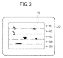
- the scanning line number 80 is stored in the parameter storage region 9d via the step like measurement condition setting program 9a.
- Parameters 50V, 100V, 150V, 200V and 250V are stored in this order in the measurement condition table 9e as parameters for the applied voltage.
- a measurement is performed while varying the applied voltage in 5 steps, in that from 50V to 250V, for the first line to 80th line of the main scanning a XY scanning is performed while keeping the voltage (applied voltage) of the transmission signal pulse at 50V and the measurement data therefrom are sampled out, for the 81th line to 160th line the measurement data are sampled out at the applied voltage 100V, for the 161th line to 240th line the measurement data are sampled out at the applied voltage 150V, subsequently, in response to alternation of the covering scanning lines by 80 lines the applied voltage is successively set at 200V and 250V and measurements are performed.
- the step like measurement condition setting program 9a selects a parameter for the scanning region corresponding to the designated line from the measurement condition table 9e and writes the same as a selected parameter at the position of the corresponding parameter in the parameter storage region 9d.
- the respective measurement conditions parameter values
- the parameter value corresponding to the image to be selected can be input directly via the operation panel 14 without relying on the cursor designation.
- the step like measurement condition setting program 9a sets the parameter of applied voltage of 150V stored in the parameter storage region 9d on the pulser as an effective set value.
- the n line scanning program 9b performs an ultrasonic measurement by the amount of n lines for the subscanning with reference to respective parameters stored in the parameter storage region 9d and according to the value of the scanning line number n likely stored therein, after completing the measurement, performs processings to produce display data from the measurement data of the amount corresponding to the main scanning line number n and to display the measurement image at the position on a screen corresponding to the scanning area.
- processings to produce display data from the measurement data of the amount corresponding to the main scanning line number n and to display the measurement image at the position on a screen corresponding to the scanning area.
- one line for the main scanning lines corresponds to one line for the horizontal scanning lines and one line of the subscanning lines to one line of Y direction scanning lines.
- Y direction can be assumed as main scanning direction and X direction as subscanning direction.
- the Z direction can be treated as a main scanning direction or a subscanning direction.
- the MPU 8 sets the probe 3 at an original point in the designated XY scanning range, starts a horizontal scanning and receives measurement data of 256 gradations which are determined by A/D conversion of the peak values detected at respective measurement positions along the horizontal scanning. Further, in case that the display data are produced every time when the measurement data are received, the measurement data of 256 gradations are developed into display data corresponding to scanning positions in XY plane and are successively stored in respective memory positions in the image memory 11 corresponding to the display positions. The data stored in the image memory 11 are transferred to the display 12 via the display processing program and are displayed.
- the scanning line is moved by an amount of one pitch for subscanning, then the same scanning operation is repeated until subscanning amounting to n time scannings is completed, and the display data amounting to the n time subscannings are successively stored in the image memory 11 and at the same time successively displayed.
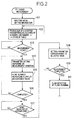
- step 101 a group of measurement parameters are stored in the parameter storage region 9d based on the inital setting conditions inputted from the operation panel 14. Then in step 102, in response to inputting of the function key for the n divided measurement the step like measurement condition setting program 9a is started m stepped parameters corresponding to the inputted step number with regard to the designated parameter are produced and stored in the measurement condition table 9e, and further the scanning line number n is calculated and stored in the parameter storage region 9d.
- step 103 the process enters into a waiting loop for judging whether the measurement is started.
- the step like measurement condition setting program 9a is executed in step 104, the initial measurement conditions are set for the respective circuits and the parameters in the parameter storage region 9d are rewritten and reset according to the measurement conditions stored in the measurement condition table 9e.
- the n line scanning program 9b is started to perform the n line scanning and the measurement images are displayed.
- step 106 it is judged whether the scanning operation is completed, if the scanning operation amounting m stepped measurements is not completed, the process returns to step 104 where in the measurement conditions in the parameter storage region 9d are rewritten by the subsequent measurement conditions stored in the measurement condition table 9e, then in step 105 the subscanning amounting to n lines of the subsequent main scanning is performed and the measurement wherein the measurement condition varies in step wise by every n line scanning is repeated.
- the measurement images as illustrated in Fig.3 are, for example, obtained.
- numeral 15 is a display area for the measurement images and the lines indicated by one-dot chain line correspond to boundaries of m divided scanning regions and are imaginary lines for illustrating m step division of the display area on the screen.
- step 107 the process enters into a judging step whether the input is via designation of images on the screen by the cursor, and when it is judged that a specific image is selected by the cursor, the parameter for the measurement condition corresponding to the display line of the selected image is read out from the measurement condition table 9e in step 108 and are written in the parameter storage region 9d.
- step 109 it is judged whether the measurement has been completed, if the measurement is not completed, the process returns to step 102 wherein the function key for the n divided measurement is inputted and another parameter for the subsequent setting is designated. For the designated other parameter the similar step wise condition setting is likely performed and a parameter for an optimum measurement condition is searched for based on the measurement images.
- step 110 the plane scanning program 9c is started for example and a flaw detection of the object under examination is performed via the plane scanning according to the optimum or proper measurement condition set in the previous step.
- the order of a designated image on the display screen can be calculated in the following manner, in that the vertical address (1 ⁇ 400) of the cursor is obtained from the display 12, then the address number is divided by n for the n line scanning and finally 1 is added to the integer part of the quotient to determined the order.
- a measurement condition to be selected can be set by directly inputting a determined reference numeral or measurement parameter via the operation panel 14.
- a plurality of measurements determined by the step number can be performed once, moreover images of different measurement conditions are successively displayed, accordingly the relation between difference of the measurement condition and the measurement images is easily grasped. Further, in the present procedure after determining another parameter the previous parameter can be reselected via second time step setting, therefore a proper measurement condition can be easily selected and no significant time is required for the measurement condition setting.
- parameters which can be selected as a measurement condition set in step wise include all of the parameters stored in the parameter storage region 9d such as number of times n of subscanning, probe height h, scanning width (Wx, Wy), coordinate of scan starting point (Xo, Yo), gate position to, gate width Wo, receiver gain Go, applied voltage Vo on the probe from the pulser, measurement pitch Po, pulse creating interval Lo from the pulser, trigger level To of the pulser and threshold level THo for judging whether or not a measurement data is defective, are stored, and the manner of the step wise division is not limited to the uniform division as in the case of the applied voltage.
- an object for the measurement is the object under examination 17 as illustrated in Fig.4.
- a plating layer having a predetermined width is provided, and inside the object a metal wire 19 having rectangular cross section is embedded.
- the probe 3 of a focusing type probe is positioned by inputting a probe height via the operation panel 14 so that the focal point of the probe comes onto the surface position of the object under examination 17 depending on the focal distance.
- the XY scanning range is set so as to cover the range including the object under examination 17 and to permit the m stepped successive measurement.
- standard measurement conditions therefor are provided as their initial conditions.
- the minus symbol of the pitch for the probe height implies to move the probe 3 close to the side of the object under examination 17, in other words the height is gradually lowered.
- the position at -3mm for the height of the probe 3 can be selected.
- An operator can input the selected position through the operation panel 14 either by moving the cursor onto the image corresponding to the probe height at -3mm or by directly inputting the numeral value of -3mm.
- the third display image is designated, the third parameter -3mm stored in the measurement condition table 9e is selected in step 108 and a parameter which sets the height of the probe 3 at the position of -3mm is written in the parameter storage region 9d.
- the plating layer 18 in the first step image appears in an image 18a having trailing echo due to echo of the plating layer 18, and in the images of the subsequent steps the images having training echo are disappeared.
- the image of the wire material 19 appears in the image of the second step in an image 19a of its echo
- the wire material image 19a appears in an image having trailing echo and in the images of the subsequent steps the images having trailing echo disappear.
- the image of the second step is selected in the same manner as explained above.
- the second display image is designated, the second parameter 1.0 ⁇ sec. stored in the measurement condition table 9e is selected in step 108 and a parameter representing the position of 1.0 ⁇ sec. which sets the gate position at the position of 1.0 ⁇ sec. is written in the parameter storage region 9d.
- the image of the third step is selected in the same manner as explained above.
- the third display image is designated, the third parameter 1000 n sec. stored in the measurement condition table 9e is selected in step 108 and a parameter for the gate width which sets the gate width at 1000 n sec. is written in the parameter storage region 9d.
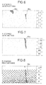
- the image of the first step is generally dark and unclear and the images of later steps become bright and clear.
- the images of the fourth and fifth steps contains a lot of noises and in the image of the fifth step the image of the wire material 19 is dominated by noises.
- the image of the third step is selected in the same manner as explained above, and a parameter of gain of 25dB is written in the parameter storage region 9d.
- a desirable C scope measurement image of the object under examination 17 can be obtained. Further, if it is desired to take a cross sectional images thereof, such is obtained by executing at this stage a scanning program which produces a B scope measurement image.
- the measurement images are sampled out by successively scanning the XY scanning region under 5 stepped measurement conditions.
- both plating layer 18 and the wire material 19 run substantially parallel with respect to the surface of the object under examination 17, substantially the same images are obtained through the successive scanning operations even when the respective scanning regions for the 5 step are different.
- a method of obtaining images of m stepped measurement conditions as explained previously wherein the probe is returned to the origin of the XY scanning region after every n lines scanning to scan the same XY scanning region can be applied to the object under examination 17 for its inspection.
- substantially the same images will be obtained for the object under examination 17 as explained above.
- the present method is recomended to apply to an object under examination wherein the internal conditions are different from one scanning region to another scanning region in the range of XY scanning region.
- the m stepped measurement images are displayed at once on the screen, however when the number of m in m steps is large number, the m stepped measurement images can be displayed in 2 or more than 2 screen pictures while allotting a plurality of measurement images less than m for one screen picture, and through switching a plurality of the screen pictures the measurement images are compared and selected.
Landscapes
- Physics & Mathematics (AREA)
- Engineering & Computer Science (AREA)
- Health & Medical Sciences (AREA)
- Acoustics & Sound (AREA)
- Radar, Positioning & Navigation (AREA)
- Remote Sensing (AREA)
- Life Sciences & Earth Sciences (AREA)
- General Physics & Mathematics (AREA)
- Immunology (AREA)
- Chemical & Material Sciences (AREA)
- General Health & Medical Sciences (AREA)
- Hematology (AREA)
- Analytical Chemistry (AREA)
- Biochemistry (AREA)
- Pathology (AREA)
- Molecular Biology (AREA)
- Biomedical Technology (AREA)
- Computer Networks & Wireless Communication (AREA)
- Urology & Nephrology (AREA)
- Biotechnology (AREA)
- Cell Biology (AREA)
- Microbiology (AREA)
- Food Science & Technology (AREA)
- Medicinal Chemistry (AREA)
- Investigating Or Analyzing Materials By The Use Of Ultrasonic Waves (AREA)
- Ultra Sonic Daignosis Equipment (AREA)
Claims (10)
- Instrument d'inspection et d'imagerie par ultrasons comprenant :un moyen (9a) pour diviser une plage de balayage d'un objet sous examen selon m éléments (m est un entier égal ou supérieur à 2) suivant une direction de sous-balayage ;un moyen (9a) pour établir une condition prise parmi des conditions de mesure ou un paramètre pris parmi des paramètres de mesure pour chacun de m pas ;un moyen (9b) pour réaliser une mesure par ultrasons sur l'objet sous examen tout en allouant successivement les conditions de mesure selon m pas ou les paramètres de mesure selon m pas aux régions de balayage respectives qui sont divisées suivant la direction de sous-balayage ;un moyen d'affichage (12) pour afficher une pluralité d'images de mesure qui sont obtenues sous les conditions de mesure selon m pas sur un écran d'affichage de manière à permettre une comparaison des images de mesure sur l'écran d'affichage ; etun moyen (9e, 9b) pour établir une condition prise parmi les conditions de mesure selon m pas ou un paramètre pris parmi les paramètres de mesure selon m pas qui correspond à une image sélectionnée à partir de l'écran affiché en tant que condition de mesure ou paramètre de mesure pour l'objet sous examen.
- Instrument d'inspection et d'imagerie par ultrasons selon la revendication 1, dans lequel les balayages selon m pas sont établis sur la même plage de balayage dans le plan et dans lequel chaque allocation successive des conditions de mesure selon m pas ou des paramètres de mesure selon m pas est répétée sur la même plage de balayage dans le plan afin de réaliser m mesures.
- Instrument d'inspection et d'imagerie par ultrasons selon la revendication 1, dans lequel les images de la pluralité des images de mesure sont formées en tant qu'une seule image d'écran d'affichage, les lignes de balayage horizontal sur l'écran d'affichage correspondent aux lignes de balayage principal pendant la mesure et chacune des images de mesure est affichée sur une région de balayage respective en tant qu'image de lignes de balayage horizontal d'un nombre correspondant à une partie entière d'un quotient déterminé en divisant le nombre total de lignes de balayage horizontal dans la plage d'affichage pour une image d'écran par m.
- Instrument d'inspection et d'imagerie par ultrasons selon la revendication 2, dans lequel les images de la pluralité des images de mesure sont formées en tant qu'une seule image d'écran d'affichage, les lignes de balayage horizontal sur l'écran d'affichage correspondent aux lignes de balayage principal pendant la mesure et chacune des images de mesure est affichée sur une région de balayage respective en tant qu'image de lignes de balayage horizontal d'un nombre correspondant à une partie entière d'un quotient déterminé en divisant le nombre total de lignes de balayage horizontal dans la plage d'affichage pour une image d'écran par m.
- Instrument d'inspection et d'imagerie par ultrasons selon la revendication 3, comprenant en outre un processeur, une mémoire et une unité d'entrée, dans lequel le nombre m et la plage de la condition de mesure ou la plage du paramètre de mesure sont entrés via ladite unité d'entrée et comprenant en outre un moyen pour produire les conditions de mesure selon m pas ou les paramètres de mesure selon m pas en considération de la plage entrée de la condition de mesure ou de la plage entrée du paramètre de mesure conformément au nombre m et pour stocker la même chose dans ladite mémoire, dans lequel les conditions de mesure selon m pas ou les paramètres de mesure selon m pas sont lus successivement à partir de ladite mémoire et sont établis.
- Instrument d'inspection et d'imagerie par ultrasons selon la revendication 4, comprenant en outre un processeur, une mémoire et une unité d'entrée, dans lequel le nombre m et la plage de la condition de mesure ou la plage du paramètre de mesure sont entrés via ladite unité d'entrée et comprenant en outre un moyen pour produire les conditions de mesure selon m pas ou les paramètres de mesure selon m pas en considération de la plage entrée de la condition de mesure ou de la plage entrée du paramètre de mesure conformément au nombre m et pour stocker la même chose dans ladite mémoire, dans lequel les conditions de mesure selon m pas ou les paramètres de mesure selon m pas sont lus successivement à partir de ladite mémoire et sont établis.
- Appareil d'inspection et d'imagerie par ultrasons selon la revendication 6, dans lequel la sélection d'image est réalisée via ladite unité d'entrée en désignant l'une des images de mesure qui sont affichées sur l'image d'écran d'affichage, par l'intermédiaire de la lecture suivant l'adresse verticale de la position d'image désignée sur l'image d'écran, l'ordre de la région d'affichage de l'image de mesure sur l'image d'écran d'affichage étant déterminé et la condition de mesure ou le paramètre de mesure étant sélectionné en fonction de l'ordre déterminé.
- Instrument d'inspection et d'imagerie par ultrasons selon la revendication 6, dans lequel la plage de la condition de mesure ou la plage du paramètre de mesure est définie par une position de référence et par un nombre de pas depuis la position de référence.
- Instrument d'inspection et d'imagerie par ultrasons selon la revendication 7, comprenant en outre un moyen pour calculer un nombre de lignes de balayage correspondant à une partie entière de 1/m fois le nombre total de lignes de balayage horizontal sur l'image d'écran d'affichage conformément au nombre m et pour allouer la même chose pour les régions de balayage respectives.
- Instrument d'inspection et d'imagerie par ultrasons selon la revendication 6, dans lequel les conditions de mesure selon m pas ou les paramètres de mesure selon m pas sont établis successivement conformément à l'ordre stocké dans ladite mémoire en tant que conditions de mesure respectives ou que paramètres de mesure respectifs, les mesures respectives étant réalisées comme ci-après, les images de mesure et les conditions de mesure ou les paramètres de mesure correspondants étant affichés successivement sur l'écran conformément à l'ordre, la condition de mesure ou le paramètre de mesure affiché étant entré via ladite unité d'entrée, et une condition prise parmi les conditions de mesure selon m pas ou un paramètre pris parmi les paramètres de mesure selon m pas correspondant à l'image de mesure sélectionnée est sélectionné.
Applications Claiming Priority (4)
| Application Number | Priority Date | Filing Date | Title |
|---|---|---|---|
| JP16760/93 | 1993-01-06 | ||
| JP1676093 | 1993-01-06 | ||
| JP1676093 | 1993-01-06 | ||
| PCT/JP1994/000003 WO1994016321A1 (fr) | 1993-01-06 | 1994-01-05 | Appareil de sondage d'image avec des ondes ultrasoniques |
Publications (3)
| Publication Number | Publication Date |
|---|---|
| EP0642016A1 EP0642016A1 (fr) | 1995-03-08 |
| EP0642016A4 EP0642016A4 (fr) | 1997-04-16 |
| EP0642016B1 true EP0642016B1 (fr) | 2002-04-10 |
Family
ID=11925192
Family Applications (1)
| Application Number | Title | Priority Date | Filing Date |
|---|---|---|---|
| EP94903997A Expired - Lifetime EP0642016B1 (fr) | 1993-01-06 | 1994-01-05 | Appareil de sondage d'image avec des ondes ultrasoniques |
Country Status (6)
| Country | Link |
|---|---|
| US (1) | US5481917A (fr) |
| EP (1) | EP0642016B1 (fr) |
| JP (1) | JP3171340B2 (fr) |
| KR (1) | KR100284356B1 (fr) |
| DE (1) | DE69430346T2 (fr) |
| WO (1) | WO1994016321A1 (fr) |
Families Citing this family (9)
| Publication number | Priority date | Publication date | Assignee | Title |
|---|---|---|---|---|
| JP3723665B2 (ja) * | 1997-07-25 | 2005-12-07 | フクダ電子株式会社 | 超音波診断装置 |
| JP3025648B2 (ja) * | 1996-08-30 | 2000-03-27 | 株式会社九州エレクトロニクスシステム | 半導体のボンディング不良検出装置 |
| DE19941120A1 (de) * | 1999-08-25 | 2001-07-05 | Mannesmann Ag | Verfahren zur Beurteilung des Bereiches der Mittenebene von Stranggußbrammen |
| FR2836556A1 (fr) * | 2002-02-22 | 2003-08-29 | Marais Atel Du | Dispositif a ultrasons permettant de capter et reproduire des formes tridimensionnelles a partir de cibles pour mesurer des volumes |
| US7188526B2 (en) * | 2005-06-29 | 2007-03-13 | Battelle Energy Alliance, Llc | Ultrasonic transducer |
| JP5835903B2 (ja) * | 2011-02-03 | 2015-12-24 | 株式会社東芝 | 超音波診断装置 |
| US8770029B2 (en) * | 2011-10-04 | 2014-07-08 | General Electric Company | Method and apparatus for ultrasonic testing |
| CN103018332A (zh) * | 2012-12-05 | 2013-04-03 | 中国电子科技集团公司第四十五研究所 | 超声扫描显微镜智能扫描的实现方法 |
| KR102740540B1 (ko) * | 2022-01-12 | 2024-12-12 | 김효섭 | 상수도관 내부용접부 품질검사장치의 초점거리 캘리브레이션 방법 |
Family Cites Families (9)
| Publication number | Priority date | Publication date | Assignee | Title |
|---|---|---|---|---|
| US4747411A (en) * | 1984-03-28 | 1988-05-31 | National Biochemical Research Foundation | Three-dimensional imaging system |
| CA1242267A (fr) * | 1984-09-25 | 1988-09-20 | Rainer Fehr | Affichage en temps reel d'une image composite engendree par ultrasons |
| JPH0614031B2 (ja) * | 1986-09-29 | 1994-02-23 | 日立建機株式会社 | 超音波探傷装置 |
| JPH0373846A (ja) * | 1989-08-14 | 1991-03-28 | Hitachi Constr Mach Co Ltd | 超音波測定装置 |
| FR2652654A1 (fr) * | 1989-09-29 | 1991-04-05 | Philips Electronique Lab | Echographe ultrasonore utilisant un dispositif numerique de formation de voies en reception. |
| US5062429A (en) * | 1989-12-15 | 1991-11-05 | General Electric Company | Ultrasound imaging system probe with alternate transducer polling for common-mode noise rejection |
| KR0171605B1 (ko) * | 1990-05-30 | 1999-05-01 | 오까다 모도 | 초음파 영상검사장치 |
| JP2588050B2 (ja) * | 1990-06-29 | 1997-03-05 | 日立建機株式会社 | 超音波映像検査装置 |
| JP3070133B2 (ja) * | 1991-05-28 | 2000-07-24 | 株式会社日立メディコ | 超音波診断装置 |
-
1994
- 1994-01-05 US US08/290,960 patent/US5481917A/en not_active Expired - Fee Related
- 1994-01-05 WO PCT/JP1994/000003 patent/WO1994016321A1/fr active IP Right Grant
- 1994-01-05 DE DE69430346T patent/DE69430346T2/de not_active Expired - Fee Related
- 1994-01-05 JP JP51298694A patent/JP3171340B2/ja not_active Expired - Lifetime
- 1994-01-05 KR KR1019940702770A patent/KR100284356B1/ko not_active IP Right Cessation
- 1994-01-05 EP EP94903997A patent/EP0642016B1/fr not_active Expired - Lifetime
Also Published As
| Publication number | Publication date |
|---|---|
| DE69430346D1 (de) | 2002-05-16 |
| JP3171340B2 (ja) | 2001-05-28 |
| KR100284356B1 (ko) | 2001-06-01 |
| KR950700538A (ko) | 1995-01-16 |
| US5481917A (en) | 1996-01-09 |
| EP0642016A4 (fr) | 1997-04-16 |
| DE69430346T2 (de) | 2002-10-31 |
| WO1994016321A1 (fr) | 1994-07-21 |
| EP0642016A1 (fr) | 1995-03-08 |
Similar Documents
| Publication | Publication Date | Title |
|---|---|---|
| US6661507B2 (en) | Pattern inspecting system and pattern inspecting method | |
| US5293326A (en) | Ultrasonic inspection and imaging instrument | |
| EP0642016B1 (fr) | Appareil de sondage d'image avec des ondes ultrasoniques | |
| EP0189137A2 (fr) | Système ultrasonique de détection de défauts | |
| US8421802B2 (en) | Peak visualization enhancement display system for use with a compressed waveform display on a non-destructive inspection instrument | |
| US20030190069A1 (en) | Method of measuring a line edge roughness of micro objects in scanning microscopes | |
| US6301512B1 (en) | Ultrasonic data analysis and display system | |
| US4261040A (en) | Method and apparatus for the analysis of scanned data | |
| US5179954A (en) | Ultrasonic inspection and imaging instrument | |
| EP0051089A2 (fr) | Méthode d'analyse de données balayées | |
| JPH0830698B2 (ja) | 超音波測定方式 | |
| JPH0430489Y2 (fr) | ||
| JP2881702B2 (ja) | 超音波探査映像装置の焦点合わせ方法およびこの方法を用いる超音波探査映像装置 | |
| JPH08220073A (ja) | 渦電流探傷装置の欠陥寸法評価装置 | |
| WO1994016321A9 (fr) | ||
| JPH0614031B2 (ja) | 超音波探傷装置 | |
| JP3040051B2 (ja) | 超音波映像検査装置 | |
| JPH0763739A (ja) | 自動超音波探傷方法 | |
| JPH06213878A (ja) | 超音波映像検査装置 | |
| JP2640878B2 (ja) | 超音波映像検査装置 | |
| JPH10288609A (ja) | 超音波探傷装置 | |
| JP2784206B2 (ja) | 超音波検査装置 | |
| JPH10143673A (ja) | 画像処理装置 | |
| JP2765916B2 (ja) | 超音波検査装置 | |
| JPH03125964A (ja) | 超音波検査装置 |
Legal Events
| Date | Code | Title | Description |
|---|---|---|---|
| PUAI | Public reference made under article 153(3) epc to a published international application that has entered the european phase |
Free format text: ORIGINAL CODE: 0009012 |
|
| 17P | Request for examination filed |
Effective date: 19940829 |
|
| AK | Designated contracting states |
Kind code of ref document: A1 Designated state(s): DE FR GB IT |
|
| A4 | Supplementary search report drawn up and despatched |
Effective date: 19970224 |
|
| AK | Designated contracting states |
Kind code of ref document: A4 Designated state(s): DE FR GB IT |
|
| 17Q | First examination report despatched |
Effective date: 19991008 |
|
| GRAG | Despatch of communication of intention to grant |
Free format text: ORIGINAL CODE: EPIDOS AGRA |
|
| RTI1 | Title (correction) |
Free format text: APPARATUS FOR PROBING IMAGES WITH ULTRASONIC WAVES |
|
| GRAG | Despatch of communication of intention to grant |
Free format text: ORIGINAL CODE: EPIDOS AGRA |
|
| GRAH | Despatch of communication of intention to grant a patent |
Free format text: ORIGINAL CODE: EPIDOS IGRA |
|
| GRAH | Despatch of communication of intention to grant a patent |
Free format text: ORIGINAL CODE: EPIDOS IGRA |
|
| REG | Reference to a national code |
Ref country code: GB Ref legal event code: IF02 |
|
| GRAA | (expected) grant |
Free format text: ORIGINAL CODE: 0009210 |
|
| AK | Designated contracting states |
Kind code of ref document: B1 Designated state(s): DE FR GB IT |
|
| REF | Corresponds to: |
Ref document number: 69430346 Country of ref document: DE Date of ref document: 20020516 |
|
| ET | Fr: translation filed | ||
| PLBE | No opposition filed within time limit |
Free format text: ORIGINAL CODE: 0009261 |
|
| STAA | Information on the status of an ep patent application or granted ep patent |
Free format text: STATUS: NO OPPOSITION FILED WITHIN TIME LIMIT |
|
| 26N | No opposition filed |
Effective date: 20030113 |
|
| PGFP | Annual fee paid to national office [announced via postgrant information from national office to epo] |
Ref country code: DE Payment date: 20041231 Year of fee payment: 12 |
|
| PG25 | Lapsed in a contracting state [announced via postgrant information from national office to epo] |
Ref country code: IT Free format text: LAPSE BECAUSE OF NON-PAYMENT OF DUE FEES Effective date: 20050105 |
|
| PGFP | Annual fee paid to national office [announced via postgrant information from national office to epo] |
Ref country code: GB Payment date: 20050105 Year of fee payment: 12 |
|
| PGFP | Annual fee paid to national office [announced via postgrant information from national office to epo] |
Ref country code: FR Payment date: 20050110 Year of fee payment: 12 |
|
| PG25 | Lapsed in a contracting state [announced via postgrant information from national office to epo] |
Ref country code: GB Free format text: LAPSE BECAUSE OF NON-PAYMENT OF DUE FEES Effective date: 20060105 |
|
| PG25 | Lapsed in a contracting state [announced via postgrant information from national office to epo] |
Ref country code: FR Free format text: LAPSE BECAUSE OF NON-PAYMENT OF DUE FEES Effective date: 20060131 |
|
| PG25 | Lapsed in a contracting state [announced via postgrant information from national office to epo] |
Ref country code: DE Free format text: LAPSE BECAUSE OF NON-PAYMENT OF DUE FEES Effective date: 20060801 |
|
| GBPC | Gb: european patent ceased through non-payment of renewal fee |
Effective date: 20060105 |
|
| REG | Reference to a national code |
Ref country code: FR Ref legal event code: ST Effective date: 20060929 |
|
| PGFP | Annual fee paid to national office [announced via postgrant information from national office to epo] |
Ref country code: IT Payment date: 20060131 Year of fee payment: 13 |
|
| PGRI | Patent reinstated in contracting state [announced from national office to epo] |
Ref country code: IT Effective date: 20080301 |
|
| PGRI | Patent reinstated in contracting state [announced from national office to epo] |
Ref country code: IT Effective date: 20080301 |