EP0640232B1 - Procede destine a reunir des images et appareil pour realiser ce procede - Google Patents
Procede destine a reunir des images et appareil pour realiser ce procede Download PDFInfo
- Publication number
- EP0640232B1 EP0640232B1 EP93911126A EP93911126A EP0640232B1 EP 0640232 B1 EP0640232 B1 EP 0640232B1 EP 93911126 A EP93911126 A EP 93911126A EP 93911126 A EP93911126 A EP 93911126A EP 0640232 B1 EP0640232 B1 EP 0640232B1
- Authority
- EP
- European Patent Office
- Prior art keywords
- image
- oriented component
- oriented
- patterns
- source
- Prior art date
- Legal status (The legal status is an assumption and is not a legal conclusion. Google has not performed a legal analysis and makes no representation as to the accuracy of the status listed.)
- Expired - Lifetime
Links
- 238000000034 method Methods 0.000 title claims description 94
- 239000002131 composite material Substances 0.000 claims description 117
- 230000006870 function Effects 0.000 claims description 66
- 239000003086 colorant Substances 0.000 claims description 13
- 230000001419 dependent effect Effects 0.000 claims description 8
- 230000003190 augmentative effect Effects 0.000 claims description 5
- 230000004927 fusion Effects 0.000 description 36
- 238000012545 processing Methods 0.000 description 21
- 238000007499 fusion processing Methods 0.000 description 16
- 238000013459 approach Methods 0.000 description 7
- 238000010276 construction Methods 0.000 description 6
- 230000000694 effects Effects 0.000 description 4
- 238000012986 modification Methods 0.000 description 4
- 230000004048 modification Effects 0.000 description 4
- 238000004458 analytical method Methods 0.000 description 3
- 230000000750 progressive effect Effects 0.000 description 3
- 238000012935 Averaging Methods 0.000 description 2
- 101100246550 Caenorhabditis elegans pyr-1 gene Proteins 0.000 description 2
- 238000003491 array Methods 0.000 description 2
- 238000000354 decomposition reaction Methods 0.000 description 2
- 238000009795 derivation Methods 0.000 description 2
- 238000005286 illumination Methods 0.000 description 2
- 238000012360 testing method Methods 0.000 description 2
- 230000001131 transforming effect Effects 0.000 description 2
- 230000001174 ascending effect Effects 0.000 description 1
- 239000000872 buffer Substances 0.000 description 1
- 238000004364 calculation method Methods 0.000 description 1
- 238000006243 chemical reaction Methods 0.000 description 1
- 230000006835 compression Effects 0.000 description 1
- 238000007906 compression Methods 0.000 description 1
- 230000007812 deficiency Effects 0.000 description 1
- 230000001934 delay Effects 0.000 description 1
- 238000010586 diagram Methods 0.000 description 1
- 230000007717 exclusion Effects 0.000 description 1
- 230000004438 eyesight Effects 0.000 description 1
- 238000001914 filtration Methods 0.000 description 1
- 238000003384 imaging method Methods 0.000 description 1
- 238000007689 inspection Methods 0.000 description 1
- 238000002595 magnetic resonance imaging Methods 0.000 description 1
- 230000014759 maintenance of location Effects 0.000 description 1
- 239000011159 matrix material Substances 0.000 description 1
- 239000000203 mixture Substances 0.000 description 1
- 238000011045 prefiltration Methods 0.000 description 1
- 238000003672 processing method Methods 0.000 description 1
- 230000003595 spectral effect Effects 0.000 description 1
- 230000002123 temporal effect Effects 0.000 description 1
- 238000003325 tomography Methods 0.000 description 1
- 230000016776 visual perception Effects 0.000 description 1
Images


Classifications
-
- G—PHYSICS
- G06—COMPUTING; CALCULATING OR COUNTING
- G06T—IMAGE DATA PROCESSING OR GENERATION, IN GENERAL
- G06T5/00—Image enhancement or restoration
- G06T5/50—Image enhancement or restoration by the use of more than one image, e.g. averaging, subtraction
-
- H—ELECTRICITY
- H04—ELECTRIC COMMUNICATION TECHNIQUE
- H04N—PICTORIAL COMMUNICATION, e.g. TELEVISION
- H04N19/00—Methods or arrangements for coding, decoding, compressing or decompressing digital video signals
- H04N19/20—Methods or arrangements for coding, decoding, compressing or decompressing digital video signals using video object coding
- H04N19/23—Methods or arrangements for coding, decoding, compressing or decompressing digital video signals using video object coding with coding of regions that are present throughout a whole video segment, e.g. sprites, background or mosaic
-
- H—ELECTRICITY
- H04—ELECTRIC COMMUNICATION TECHNIQUE
- H04N—PICTORIAL COMMUNICATION, e.g. TELEVISION
- H04N7/00—Television systems
- H04N7/18—Closed-circuit television [CCTV] systems, i.e. systems in which the video signal is not broadcast
- H04N7/181—Closed-circuit television [CCTV] systems, i.e. systems in which the video signal is not broadcast for receiving images from a plurality of remote sources
-
- G—PHYSICS
- G06—COMPUTING; CALCULATING OR COUNTING
- G06T—IMAGE DATA PROCESSING OR GENERATION, IN GENERAL
- G06T2207/00—Indexing scheme for image analysis or image enhancement
- G06T2207/20—Special algorithmic details
- G06T2207/20016—Hierarchical, coarse-to-fine, multiscale or multiresolution image processing; Pyramid transform
-
- G—PHYSICS
- G06—COMPUTING; CALCULATING OR COUNTING
- G06T—IMAGE DATA PROCESSING OR GENERATION, IN GENERAL
- G06T2207/00—Indexing scheme for image analysis or image enhancement
- G06T2207/20—Special algorithmic details
- G06T2207/20212—Image combination
- G06T2207/20221—Image fusion; Image merging
Definitions
- the invention relates to a method for fusing two or more source images to form a composite image with extended information content and apparatus for forming the composite image from the source images.
- Image fusion is a process that combines two or more source images to form a single composite image with extended information content.
- images from different sensors such as infra-red and visible cameras, computer aided tomography (CAT) and magnetic resonance imaging (MRI) systems, are combined to form the composite image.
- CAT computer aided tomography
- MRI magnetic resonance imaging
- Multiple images of a given scene taken with different types of sensors, such as visible and infra-red cameras, or images taken with a given type of sensor and scene but under different imaging condition, such as with different scene illumination or camera focus may be combined.
- Image fusion is successful to the extent that: (1) the composite image retains all useful information from the source images, (2) the composite image does not contain any artifacts generated by the fusion process, and (3) the composite image looks natural, so that it can be readily interpreted through normal visual perception by humans or machines.
- useful information as determined by the user of the composite image determines which features of the different source images are selected for inclusion in the composite image.
- Known pattern selective image fusion tries to overcome these deficiencies by identifying salient features in the source images and preserving these features in the composite at full contrast.
- Each source image is first decomposed into a set of primitive pattern elements.
- a set of pattern elements for the composite image is then assembled by selecting salient patterns from the primitive pattern elements of the source images.
- the composite image is constructed from its set of primitive pattern elements.
- the Laplacian pyramid approach to image fusion is perhaps the best known pattern-selective method.
- BURT first disclosed the use of image fusion techniques based on the Laplacian pyramid for binocular fusion in human vision.
- U.S. Patent No. 4,661,986 disclosed the use of the Laplacian technique for the construction of an image with an extended depth of field from a set of images taken with a fixed camera but with different focal settings.
- A. Toet in Machine Vision and Applications, V. 3, pages 1-11 (1990) has disclosed a modified Laplacian pyramid that has been used to combine visible and IR images for surveillance applications. More recently M. Pavel et al in Proceedings of the AIAA Conference on Computing in Aerospace, V.
- a Laplacian transform is used to decompose each source image into regular arrays of Gaussian-like basis functions of many sizes. These patterns are sometimes referred to as basis functions of the pyramid transform, or as wavelets.
- the multiresolution pyramid of source images permits coarse features to be analyzed at low resolution and fine features to be analyzed at high resolution.
- Each sample value of a pyramid represents the amplitude associated with a corresponding basis function.
- the combination process selects the most prominent of these patterns from the source images for inclusion in the fused image.
- the source pyramids are combined through selection on a sample by sample basis to form a composite pyramid.
- the component patterns take the form of circularly symmetric Gaussian-like intensity functions.
- Component patterns of a given scale tend to have large amplitude where there are distinctive features in the image of about that scale.
- Most image patterns can be described as being made up of edge-like primitives. The edges in turn are represented within the pyramid by collections of component patterns.
- Laplacian pyramid technique has been found to provide good results, sometimes visible artifacts are introduced into the composite image. These may occur, for example, along extended contours in the scene due to the fact that such higher level patterns are represented in the Laplacian pyramid rather indirectly.
- An intensity edge is represented in the Laplacian pyramid by Gaussian patterns at all scales with positive values on the lighter side of the edge, negative values on the darker, and zero at the location of the edge itself. If not all of these primitives survive the selection process, the contour is not completely rendered in the composite.
- An additional shortcoming is due to the fact that the Gaussian-like component patterns have non-zero mean values. Errors in the selection process lead to changes in the average image intensity within local regions of a scene.
- the selection process is intrinsically binary, the basis function from one or the other source image is chosen. If the magnitude of the basis functions vary, for example because of noise in the image or sensor motion, the selection process may alternately select the basis functions from different source images. This leads to unduly perceptible artifacts such as flicker and crawlers.
- a method of forming a composite image I c from N source images I n where n 1 to N and N is greater than one, said method comprising the steps of:
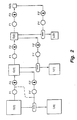
- FIG. 2 A flow chart for the generation of the Gaussian and Laplacian pyramids of a source image is shown in Fig. 2.
- the Gaussian G(0) is the source image.
- the Gaussian G(0) is then filtered by F1, a low pass filter having a Gaussian rolloff, and subsampled by F2, to remove alternate pixels in each row and alternate rows, to form the first level Gaussian G(1).
- the lower level Gaussians G(n) are formed successively in the same way.
- the Laplacian L(n) corresponding to the Gaussian at each level of the pyramid is formed by restoring the subsampled data to the next lowest level of the Gaussian pyramid (by inserting zero-valued samples between the given samples F2' then applying an interpolation filter F1') and subtracting from the Gaussian of the given level.
- the Laplacian formed in this way is known as the Reduce-Expand (RE) Laplacian.
- the Laplacian can be formed without subsampling and reinterpolation as shown by the dotted line Fig. 2. This is called a filter-subtract-decimate (FSD) Laplacian.
- Fig. 3 a method for reconstructing an image from the Laplacian pyramid is illustrated. In this method the Laplacians are interpolated and summed to reproduce the original image (i.e. the inverse RE Laplacian pyramid transform).
- the composite image I c is recovered from its Laplacian pyramid representation P c through an inverse pyramid transform such as that disclosed by BURT and in U.S. Patent No. 4,692,806.
- An embodiment of a method in accordance with the invention for forming a composite image from a plurality of source images comprises the steps of transforming the source images into a feature-based representation by decomposing each source image I n into a set of component patterns P n (m) using a plurality of oriented functions; computing a saliency measure for each component pattern; combining the salient features from the source images by assembling patterns from the source image pattern sets P n (m) guided by the saliency measures S n (m) associated with the various source images; and constructing the composite image I c through an inverse transform from its component patterns P c (m).
- a saliency estimation process is applied individually to each set of component patterns P n (m) to determine a saliency measure S n (m) for each pattern.
- saliency can be based directly on image data, I n , and/or on the component pattern representation P n (m) and/or it can take into account information from other sources.
- the saliency measures may relate to perceptual distinctiveness of features in the source images, or to other criteria specific to the application for which fusion is being performed (e.g., targets of interest in surveillance).
- the invention is a pattern selective method of image fusion based upon the use of oriented functions (component patterns) to represent the image and, preferably, an oriented pyramid approach that overcomes the shortcomings in the prior art and provides significantly enhanced performance.
- Each source image is, preferably, decomposed into a plurality of images I of different resolution (the pyramid of images) and then decomposing each of these images into a plurality of sets of oriented component patterns.
- the oriented component patterns are, preferably edge-like pattern elements of many scales and orientations using the oriented pyramid.
- the use of the oriented pyramid improves the retention of edge-like source image patterns in the composite image.
- a pyramid is used that has component patterns with zero (or near zero) mean value.
- Component patterns are, preferably, combined through a weighted average rather than a simple selection process. The most prominent of these patterns are selected for inclusion in the composite image at each scale and orientation.
- a local saliency analysis where saliency may be based on the local edge energy (or other task-specific measure) in the source images, is performed on each source image to determine the weights used in component combination. Selection is based on the saliency measures S n (m).
- the fused image I c is recovered from P c through an inverse pyramid transform.
- the gradient pyramid has basis functions of many sizes but, unlike the Laplacian pyramid, these are oriented and have zero mean.
- the gradient pyramid's set of component patterns P n (m) can be represented as P n (i, j, k, l) where k indicates the pyramid level (or scale), 1 indicates the orientation, and i, j the index position in the k, l array.
- the gradient pyramid value D n (i, j, k, l) is the amplitude associated with the pattern P n (i, j, k, l). It can be shown that the gradient pyramid represents images in terms of gradient-of-Gaussian basis functions of many scales and orientations.
- Wavelet image representations as disclosed for example by Rioul et al in the IEEE Signal Processing Magazine, October, 1991, pages 14-38, are oriented spatial functions, linear combinations of which can be used to define an image.
- the gradient pyramid for image I is obtained by applying gradient operators to each level of its Gaussian pyramid G(n) as described in Appendix 1. Four such gradients are used for the horizontal, vertical, and orthogonal diagonal directions in the images, respectively. The four gradients are then fused using a selection criterion such as saliency to select the components to be used to form the gradient pyramid representation of the composite image. To reconstruct the composite image from its gradient pyramid representation, the gradient operators are applied a second time to form four oriented second derivative pyramids. These are summed at each level of the pyramid to form a standard Laplacian pyramid from which the composite image is reconstructed through the usual expand and add inverse Laplacian pyramid transform.
- a pattern is salient if it carries information that is useful in interpreting the image.
- saliency will depend on the purpose for constructing the composite image and any measure of saliency will be task dependent. However, saliency generally increases with the amplitude of the elementary pattern.
- S n (i, j, k, l) be the saliency value corresponding to P n (i, j, k, l).
- D n (i, j, k, l) is the amplitude associated with the pattern P n (i, j, k, l) at position (i, j) of gradient pyramid level k and orientation l. Alternatively, it can be indicated by the prominence of that component and other components within a local neighborhood. This neighborhood is indicated by a weighting function w(i', j'): Typically the neighborhood used are the component patterns for the 3x3 array of nearest components to the particular component of interest or the 3x3 array of picture elements surrounding the picture element of interest, depending upon the way the components are indexed. For example, a 3X3 array w(i', j') can be set equal to:
- S may be related to correlation of the source image with a filter matched to the target pattern at each sample position.
- the gradient pyramid for the composite image I c is obtained by selecting components from the source pyramid basis functions P n for each set of oriented functions. Selection is repeated at each sample position based on the saliency measure.
- the selection rule commonly used in current practice is "choose max", that is, select that source image sample that has the greatest amplitude.
- a "soft switch” is preferable to strict selection; that is, when selection is between two component patterns that have quite different saliency, then the one with the larger saliency is chosen, but when selection is between components that have comparable saliency, then the composite sample value is taken to be the weighted average of the source samples.
- the combination process is then one in which the amplitude of the combined pattern element is computed as a weighted average of the amplitudes of the source pattern elements for each orientation l.
- weights used in this average are based on relative saliency measures over the source image. Weights are defined such that image components with higher saliency get disproportionately higher weight. As an example, let A be the total saliency at a given position where N is the number of source images.
- T n ⁇ S n (i, j, k, l) / A(i, j, k, l) ⁇ is the normalized saliency at the (i, j) position, l th orientation of the k th pyramid level for the n th source image.
- This sigmoid like function accentuates the difference between weights of elements that have nearly average saliency while fixing the weights for a given element at near zero or near one if its salience is significantly below or above average, respectively.
- the final step in forming the composite image I c is its reconstruction from its gradient pyramid representation P c .
- the details of the computation of the inverse gradient pyramid transform are given in Appendix 1.
- a match measure, M 12 (i, j, k, l), is computed between source images within a local neighborhood, w(i', j').
- this neighborhood weighting function is the same as that used in computing the salience measures S n (i, j, k, l).
- the composite image pattern elements are again forward as a weighted average.
- D c (i, j, k, l) w 1 (i, j, k, l) D 1 (i, j, k, l) + w 2 D 2 (i, j, k, l)
- the weights w 1 and w 2 are based both on the match and saliency measures.
- the invention also provides apparatus for forming a composite image from a plurality of source images comprising means for transforming the source images into a feature-based representation by decomposing each source image I n into a set of component patterns P n (m) using a plurality of oriented functions; means for computing a saliency measure for each component pattern; means for forming the component patterns P c (m) of the composite image by assembling patterns from the source image pattern sets P n (m) guided by the saliency measures S n (m) associated with the various source images; and means for constructing the composite image through an inverse transform from its component patterns P c (m).
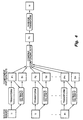
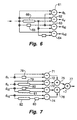
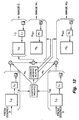
- FIGs. 5 - 8 Apparatus for implementing the method of the invention is shown in Figs. 5 - 8.
- the apparatus is shown in terms of two source images but it is understood that any number of source images can be used with appropriate modification of the apparatus.
- the frame stores FS1 and FS2, if necessary, are used to convert input source images generated in an interlaced format to a progressive scan format for subsequent processing and to adjust timing.
- a television camera output is typically in interlaced format.
- the combination of pyramid circuit P1 and frame store FS3 are used to compute the k-level Gaussian pyramid representation G a (k) of the input source image I a and the combination of circuit P2 and frame store FS4 are used to compute the n-level Gaussian pyramid representation G b (k) of the input source image I b .
- the circuits P1 and P2 provide the low pass filter with a Gaussian rolloff and the pixel subsampling (removal/ decimation of alternate pixels in each row and each row of the filtered image).
- the next operation on each level of the Gaussian pyramids G(k) is a filter (1 + w') which is performed by circuit P3 and circuit P4 to form G a f (k) and G(k) b f , respectively.
- the purpose of this pre-filter P3 and post-filter P8 are to adjust overall filter characteristics to provide an exact correspondence between intermediate results in the gradient pyramid transform and the Laplacian transform. Alternatively, this filter may be applied at other points in the sequence of transform steps. Other similar filters can be used to obtain approximate results.
- w' is a three by three binomial filter:
- the filter P3 has the form:
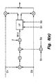
- each of the filtered Gaussian pyramids G a f (k) and G b f (k) is filtered with four oriented gradient filters representing the horizontal d h , vertical d v , right diagonal d rd , and left diagonal d ld filters respectively.
- These operations are performed by circuits P5 and P6, producing the eight oriented gradient pyramids D a (k, h), D a (k, ld), D a (k, v), D a (k, rd), D b (k, h), D b (k, rd), D b (k, v), D b (k, ld).
- the gradient operators shown here use only the two nearest neighbor samples in the particular direction, a larger number of neighbors can be used in the gradient calculation.
- circuits P5 and P6 comprise four subtractors 61, 62, 63 and 64.
- the input signal is connected directly to an input of subtractor 61 and through a single pixel delay 65 to the second input of subtractor 61.
- the output of subtractor 61 is d h .
- the input signal is connected directly to an input of subtractor 62 and through a single line delay 66 to the second input of subtractor 62.
- the output of subtractor 62 is d v .
- the input signal is connected through pixel delay 65 to an input of subtractor 63 and through line delay 66 to the second input of subtractor 63.
- the output of subtractor 61 is d rd .
- the input signal is connected directly to an input of subtractor 64 and through line delay 66 and pixel delay 65 to the second input of subtractor 64.
- the output of subtractor 61 is d ld .
- P5 and P6 can be implemented using a commercial Field Programmable Gate Array circuit (FPGA) such as XC3042 manufactured by Xilinx, Inc., San Jose, CA 95124.
- FPGA Field Programmable Gate Array circuit
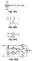
- the fusion function combines two or more images into a composite image as shown schematically in Fig. 8(a).
- the fusion function is computed on the four oriented gradient pyramids of the source images. It can also be applied to the Laplacian pyramid directly, but with less effectiveness.
- saliency may be based on absolute sample value or on a local root mean square average
- FIG. 8(e) an implementation of the local average method as shown in Fig. 4(a) is illustrated.
- a match measure, M 12 (i, j, k, l) is computed between source images D 1 (i, j, k, l) and D 2 (i, j, k, l) within a local neighborhood, w(i', j').
- this neighborhood weighting function is the same as that used in computing the salience measures S n (i, j, k, l).
- the composite image pattern elements are again forward as a weighted average. For the case of two source images.
- D c (i, j, k, l) w 1 (i, j, k, l) D 1 (i, j, k, l) + w 2 D 2 (i, j, k, l)
- the appropriate weighting function is then selected from a lookup table in the IF function.
- the weights are preferably selected as follows.
- a weighted sum of the oriented gradient pyramids are computed in each of the orientations separately, resulting in the four composite oriented gradient pyramids D c (k, h), D c (k, rd), D c (k, v), D c (k, rd).
- circuit P7 comprises four subtractors 71, 72, 73 and 74 and three adders 75, 76 and 77.
- the input signal d h is connected directly to an input of subtractor 71 and through a single pixel delay 78 to the second input of subtractor 71.
- the input signal d v is connected directly to an input of subtractor 72 and through a single line delay 79 to the second input of subtractor 72.
- the input signal d rd is connected through a single pixel delay 80 to an input of subtractor 73 and through a single line delay 81 to the second input of subtractor 73.
- the input signal d ld is connected directly to an input of subtractor 74 and through a single line delay 82 and single pixel delay 83 to the second input of subtractor 74.
- the output of subtractors 71 and 72 are connected to the inputs of adder 75.
- the output of subtractors 73 and 74 are connected to the inputs of adder 76.
- the output of adder 75 and the output of adder 76 divided by two (2) are connected to the inputs of adder 77.
- the output of adder 77 goes to frame store FS5.
- P7 can be implemented using a commercial Field Programmable Gate Array circuit (FPGA) such as XC3042 manufactured by Xilinx, Inc., San Jose, CA 95124.
- FPGA Field Programmable Gate Array circuit
- the composite Laplacian pyramid L c (k) is equivalent to the FSD Laplacian pyramid disclosed in U.S. Patent No. 4,692,806, and is stored in FS5.
- the pyramid L c (k) is then filtered by circuit P8 to produce LF c (k)
- the filter P8 has the form (1+w) where w is a five by five binomial filter: Notice that the (1/ ⁇ 2) factor in the diagonal gradient filters can be combined into a single (1/2) factor in the diagonal components in the P7 processing function as shown in Fig. 5.
- the composite image I c is reconstructed from the composite RE Laplacian pyramid LF c (k) using the combination of circuit P9 and frame store FS6 using the method described by BURT beginning with the lowest level of the pyramid.
- the circuit the circuit P9 is the same as P1 and P2.
- G c (k-1) is stored in FS6.
- the next higher resolution level G c (k-2) is then computed in the same manner, combining G c e-1 (k-1) and L c (k-2). This process is repeated until G c (0) has been computed and stored in FS7.
- FS7 is used to adjust timing and to convert the composite image from progressive scan to an interlace scan format if that is required by the image display means to be used.
- the source images G a (0) and G b (0) from the input frame stores FS1 and FS2 are filtered bv the P1 and P2 functions and stored in FS3 and FS4 in subsampled form G a (1) and G b (1).
- G a (0) and G b (0) are processed by circuits P3 through P7 and the four fusion circuits, producing L c (0) which is stored in FS5.
- the second processing pass (level 1) is started, where the images G a (1) and G b (1) (from FS3 and FS4) are filtered by circuits P1 and P2 and stored in FS3 and FS4 in subsampled form G a (2) and G b (2).
- G a (1) and G b (1) are processed by circuits P3 through P7 and the four fusion circuits, producing L c (1) which is stored in FS5. This procedure is repeated until the required number of pyramid levels are computed.
- the last pass e.g. level k
- the processing is different.
- the processing only involves reading G a (k) and G b (k) from FS3 and FS4, fusing the images with a different function, and storing the result G c (k) in FS5.
- This is the remainder or DC component, of the Laplacian pyramid L c (n).
- this is schematically shown as bypass paths around P3 through P7 and the fusion circuits.
- the fusion of the remainders may be as simple as computing the average.
- the processing at the edge of the image may be undetermined. For large images this may not be a problem since discarding the edge data has little effect on the totality of the image.
- the processing at the edges of the lower resolution levels of the pyramid affects the final reconstructed image to a significant extent. For example, if five levels of the pyramid are used, a border of 64 pixels around the image may not be reconstructed properly, if the computations at the edges of the images are not performed correctly.
- the reconstruction of a pixel includes information from the four pixels adjacent to the pixel of interest in a row.
- edge pixel For an edge pixel, two of these adjacent pixels are missing and for the next adjacent pixel in the row, one of the adjacent pixels is missing.
- the simplest way to correct for this is to insert a constant value in to matrix of pixel values.
- the value of the missing pixels are set equal to the value of the pixel of interest.
- a preferred way to implement the edge processing would be to reflect or extrapolate the pixel data at the edges of the images. For example, at the left edge of an image the two pixels to the right of the edge pixel of interest are substituted for the missing pixels.
- the construction and processing as described here can use a processor per function and per pyramid level, where the processors at each subsequent lower resolution operate at half the clock rate.
- a significantly more efficient implementation is to use one processor per function, where each processor computes or processes all pyramid levels in sequence as disclosed in U.S. Patent Application No. 07/805149, referred to above and incorporated herein by reference. This can be accomplished by using flexible frame stores (FS3, FS4 and FS5) for storing intermediate results, and adjusting the timing and/or processing clock to accommodate the additional processing time required.
- the processing of all pyramid levels by a single processor typically requires 4/3 times the number of operations required for processing one full resolution image. By using the blanking time of the input image efficiently, the actual clock rate does not have to be increased by much, if at all, to accommodate the increase in required processing.
- an interface frame store is shown in Fig. 5. These are FS1, FS2, and FS7. These are used to adjust for differences in timing between the fusion processing format and the input/output image format. One such difference is due to the timing required for the processing of the pyramid levels in sequence. Another difference may be that the image I/O is in interlace format, while the images during the fusion process may be computed using a progressive scan format.
- Fig. 9 is a timing diagram which shows when the various images and pyramid levels may be computed in a system with I/O frame stores, assuming interlace I/O for a sequence of images.
- the first time line is for successive interlaced frames having even and odd fields (e.g. 3e and 3o) spaced apart by the vertical blanking interval.
- the second time line shows the pyramid construction of the zeroth level Gaussian of the pyramid for the 3rd frame which can begin as soon as the odd field of the frame is received.
- the computation of all levels of the 3rd frame pyramid must be completed before the pyramid construction of the zeroth level Gaussian of the 4th frame begins.
- the third time line shows the pyramid composite image reconstruction for the 3rd frame which begins at the same time that pyramid construction of the 4th frame begins.
- the formatted output of the 3rd frame begins at the same time that the 5th frame is received. Thus the entire cycle for a given frame can be accomplished in two frame times. If the clock rate of the processing needs to be slightly higher than the clock rate of the I/O, then first-in, first-out buffers may be used in combination with the I/O frame stores FS1, FS2 and FS7.
- An alternative to increasing the clock for the fusion processing is to reduce the image size on which the fusion processing is being performed.
- P1, P2, P3, P4, P8, and P9 are 2D filters with 5 x 5 taps (P1, P2, P8, P9) or 3 x 3 taps (P3, P4).
- "Spread tap” versions of these filters used in double density pyramid construction can also be used. All of these are efficiently implemented using the PYR-1 circuit described in U.S. Patent Application No. 07/805149 filed December 11, 1991, incorporated herein by reference, and in the Workshop For Machine Vision, Paris, December, 1991 and generally in U.S. Patent No. 4,703,514, and sold by the David Sarnoff Research Center, Inc., Princeton, NJ 08540.
- the PYR-1 circuit can implement all the required filters, includes the required horizontal line delays, the appropriate adders and multiplexing functions, and automatic border control of the images.
- Other 2D filter circuits are available commercially, but require significant additional circuitry to incorporate all the functions to implement the methods disclosed here.
- FIG. 10 An example of a composite image formed from visible and infra-red source images is shown in Fig. 10.
- the source image from a standard visible light camera is shown in Fig. 10(a)
- the source image from an infrared cameras is shown in Fig. 10(b).
- the fused image, shown in Fig. 10(c) was obtained using the gradient pyramid and the saliency and combination rules outlined above.
- the gradient image pyramid provides an effective framework for pattern-selective image fusion.
- Advantages of the pyramid transform for fusion include the fact that it decomposes images into regular arrays of edge-like component patterns (basis functions) through simple filter operations, and the fact that reconstruction blends pattern elements over scales, orientations, and positions in a seamless manner, avoiding artifacts. These advantages provide significantly improved image fusion compared to a process based upon the Laplacian pyramid.
- the observed difference in performance can be attributed to several factors. Most important is the fact that the gradient representation has a local maximum in value at the location of an edge in the scene, while the Laplacian representation has zero value at the edge and large values either side of the edge. Since the amplitude of the sample value has been used as the measure of saliency in the present examples, edge features are more reliably captured with the gradient pyramid than with the Laplacian. Furthermore, noise in the video causes selection at some points in the scene to switch from one source image to the other from frame to frame. The resulting flicker is more visible in Laplacian than in gradient based fusion. Humans are most sensitive to temporal flicker of patterns with low spatial frequency content.
- the gradient-of-Gaussian basis functions of the gradient pyramid have a high band-pass characteristic with significantly less signal energy at low spatial frequencies than the Gaussian-like basis functions of the Laplacian pyramid.
- Images fusion techniques disclosed herein include surveillance using images from multiple sensor types or spectral bands such as visible and IR cameras; vehicle guidance using multiple sensor types (visible, IR, ...) as an aid to a driver or pilot at night or in bad weather; combining images taken with a camera's focus changed from image to image, to achieve a composite with an extended depth of field; video special effects using multiple images of difference scenes in order to obtain artistic or other special effects; industrial inspection where images taken under differing illumination and camera settings (speed, iris, etc.) are combined to eliminate shadows and highlights; and dynamic range compression for image display where a large dynamic range image (e.g., a 12 bit medical image) and a display that can render only a limited dynamic range (e.g., CRT or LCD) first generate a set of images that represent limited ranges of the original then combine these images through fusion for final display.
- a large dynamic range image e.g., a 12 bit medical image
- a display that can render only a limited dynamic range (e.g., C
- a fused composite image which is colored is known in the prior art.
- each separate source image in the prior art may be assigned a different color, such as red R, green G and blue B, and the fused composite image itself may be derived from these separate colored source images.
- the present invention proposes a different way of using color to add additional information to the display of a fused composite image, which additional information is indicative of the relative weight of the contributions of each source image to the fused composite image.
- the present invention uses color information for such a purpose by employing only luminance to define the brightness value (i.e., the value in the Y channel in the case of an NTSC video image) of each pixel of the displayed fused composite image (which is preferably derived in the manner described above), and then employing only chrominance to define the relative contribution of each source image (i.e., the respective values in the I and Q opponent color channels in the case of an NTSC video image) of each pixel of the displayed fused composite image.
- the brightness value i.e., the value in the Y channel in the case of an NTSC video image
- chrominance to define the relative contribution of each source image (i.e., the respective values in the I and Q opponent color channels in the case of an NTSC video image) of each pixel of the displayed fused composite image.
- the respective source images that contribute to the displayed fused composite image may be a first source image (e.g., an IR camera image) at its original high resolution and a second source image (e.g., a visible camera image) at its original high resolution.
- the respective source images that contribute to the displayed fused composite image may be a first image defining pyramid-derived high-resolution components of a given original source image and a second image defining pyramid-derived low-resolution components of the same given original source image
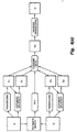
- a fusion process responsive to separate source image A and source image B applied as inputs thereto, for deriving a monochrome fused composite image C, a first weighting image W 1 and a second weighting image W 2 as respective outputs therefrom is shown.
- Each pixel sample of first weighting image W 1 and of second weighting image W 2 has a certain value between 0 and 1
- each of the respective pixel sample values of the first weighting image W 1 first has a value of 1/2 subtracted therefrom and is then multiplied by a scalar valued coefficient c A .
- each of the respective pixel sample values of the second weighting image W 2 first has a value of 1/2 subtracted therefrom and is then multiplied by a scalar valued coefficient c B .
- the respective pixel sample values of the monochrome fused composite image C comprise the Y luminance channel of an NTSC video image.
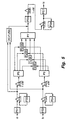
- FIG. 12 an example of the Fig. 11 fusion process that employs a Laplacian pyramid L A comprising 3 descending sample density pyramid levels L A (0), L A (1) and L A (2) that are derived from the applied pixel sample values of source image A is shown.
- a similar 3-level Laplacian pyramid L B is derived from the applied pixel sample values of source image B.
- Monochrome fused composite image C is derived from Laplacian pyramids L A and L B in a manner known in the prior-art.
- relative weighting factors w A and w B are computed for the respective pixel samples of Laplacian pyramids L A and L B in accordance with saliency measures; the value of each pixel sample of Laplacian pyramid L A is multiplied by its weighting factor w A ; the value of each pixel sample of Laplacian pyramid L B is multiplied by its weighting factor w B ; and the respective values of corresponding positioned weighted pixel samples of each level of pyramids L A and L B are summed, after which they are applied as an input to a Laplacian reconstruction pyramid L C comprising 3 ascending sample density pyramid levels L C (2), L C (1) and L C (0).
- Laplacian reconstruction pyramid L C may be implemented either as an RE Laplacian or as an FSD Laplacian.
- the output of Laplacian reconstruction pyramid L C is the monochrome fused composite image C of Fig. 11, which comprises a high resolution image composed of pixel samples at the high L(0) density.
- Fig. 12 also shows a fusion process for employing the computed weighting factors w A and w B (used in the above-described derivation of the monochrome fused composite image C) for deriving weighting images W 1 and W 2 of Fig. 11.
- each pixel sample of the image weighting functions W 1 and W 2 has a value between 0 and 1.
- These pixel sample values may represent the relative contributions of source images A and B to composite image C over all levels of the Laplacian pyramid, or, alternatively, may represent the relative contributions of two different Laplacian pyramid levels of a selected one of source images A and B to composite image C, as described in more detail below.
- the weight w(i, j, k) at each pixel sample position (i, j, k) in the Laplacian pyramid contributes to the image weighting functions W 1 and W 2 over a region that is commensurate with the size of the basis function at pyramid samples L(i, j, k).
- the fusion process includes first component-weighting reconstruction pyramid H W1 and second component-weighting reconstruction pyramid H W2 .
- each of component-weighting pyramids H W1 and H W2 is a Gaussian reconstruction pyramid (described in more detail below) composed of pyramid levels H n (2), H n (1), and H n (0).
- a combination of computed weights w A and w A is available to each of component-weighting pyramids H W1 and H W2 , which combination is selectable.
- weights w A (or alternatively weights w B ) over all these levels are forwarded to first component-weighting reconstruction pyramid H W1 and H W2 is given zero weight or ignored.
- pyramid H W1 is a Gaussian pyramid G 1 that is reconstructed through the same expand and add procedure that is used in reconstructing an image from its Laplacian pyramid representation (i.e., generated "top-down", recursively)
- G 1 (k+l: 1) indicates G 1 (k+1) expanded, or interpolated, once, so that it matches the size of G 1 (k).
- each level of HW 1 has value between 0 and 1, the base level of G 1 will have values between 0 and K+1, which may be normalized to a unit interval to form W 1 .
- W 1 G 1 (0) / (K+1).
- the reconstructed Gaussian pyramids W 1 and W 2 are obtained from H W1 and H W2 as set forth above in the description of the first case.
- W 1 2G 1 (0) / (K (K+1))
- W 2 2G 2 (0) / (K (K+1)).
- the above-described Laplacian pyramid implementation of the fusion process may be applied to a gradient pyramid implementation.
- an image is recovered from its gradient pyramid representation through a sequence of four steps.
- Second, the oriented second derivative pyramids are added to obtain an FSD Laplacian.
- the RE Laplacian is recovered from the FSD through the application of a conversion filter.
- the image is recovered from the RE Laplacian through the standard expand and add procedure.
- This procedure can be modified to recover weighting images W 1 and W 2 from weights w A and w B .
- W 1 representing the relative contribution of image A to composite image C over all levels and orientation
- This modification converts the gradient basis functions implicit in the reconstruction of images form gradient pyramids D into oriented Gaussian basis functions of the same size.
- the base level of the reconstructed Gaussian G W1 (0) is then normalized to form the weighting function W 1 .
- a modification of this procedure analogous to that described in the Laplacian pyramid case can be used to form a W 1 that represents relative contributions of the source images at low resolution pyramid levels, and a W 2 that represents relative contributes of the source images at high resolution pyramid levels.
- a monochrome composite image of two fused source images with two opponent colors employ pyramid techniques for deriving Y, I and Q video channels of an NTSC image
- pyramid techniques for deriving Y, I and Q video channels of an NTSC image
- more than two opponent colors may be employed.
- a monochrome composite image of three fused source images can be color augmented using the three opponent colors red, green and blue. to be used in a composite image.
- Other directionally sensitive techniques for measuring features in an image can also be used in the method of the invention. It is also understood that methods other than pyramid processing methods and means for providing images of different scales can be used.
- a gradient pyramid for image I can be obtained by applying a gradient operator to each level of its Gaussian pyramid representation.
- the image can be completely represented by a set of four such gradient pyramids, one each for derivatives in horizontal, vertical, and the two diagonal directions.
- w is the generating kernel, and the notation Solution 2 indicates that the image array in brackets is subsampled (down sampled) by 2 in both the horizontal and vertical directions.
- D kl is the k th level of the pyramid and the l th orientation and w is a five by five binomial filter described above.
- a method for reconstructing an image from its gradient pyramid representation comprises the steps of:
Claims (36)
- Procédé de formation d'une image composite Ic à partir de N images sources In où n = 1 à N et N est plus grand que un, ledit procédé comprenant les étapes consistant à :(a) décomposer chaque image source In en une pluralité L d'ensembles de modèles de composantes orientés Pn(m,l) en utilisant une pluralité de fonctions orientées pour représenter ladite image source In, où m est le nombre de modèles dans chacun des L ensembles pour la nième image source et l = 1 à L indique l'orientation desdits modèles orientés ;(b) calculer une mesure de prépondérance Sn (m,l) pour chaque modèle de composante orienté Pn (m,l) ;(c) calculer à partir des ensembles de modèles de composantes orientés Pn(m,l) et desdites mesures de prépondérance Sn(m,l) pour chacun desdits modèles de composantes orientés, un ensemble de modèles de composantes orientés Pc(m,l) de l'image composite Ic ; et(d) construire l'image composite Ic à partir de l'ensemble des modèles de composantes orientés calculés Pc (m,l).
- Procédé selon la revendication 1 comprenant, en outre, l'étape consistant à aligner lesdites images sources In avant l'étape (a).
- Procédé selon la revendication 1 ou 2, dans lequel l'étape (a) de la décomposition de chaque image source In en une pluralité L d'ensembles de modèles de composantes orientés Pn(m,l) comprend l'application de fonctions orientées à une image source In à chaque élément d'image de chaque image source In.
- Procédé selon la revendication 3, dans lequel lesdites fonctions orientées sont des fonctions de gradient.
- Procédé selon la revendication 1, 2, 3 ou 4, dans lequel l'étape (c) de calcul de l'ensemble des modèles de composantes orientés Pc(m,l) de l'image composite comprend la sélection des modèles de composantes orientés Pn(m,l) ayant la prépondérance la plus grande pour chaque valeur de m et l.
- Procédé selon la revendication 5, dans lequel l'étape (c) de calcul de l'ensemble des modèles de composantes orientés Pc(m,l) de l'image composite Ic comprend la sélection du modèle de composante orienté Pn(m,l) ayant la grandeur absolue la plus grande.
- Procédé selon la revendication 1, 2, 3 ou 4, dans lequel l'étape (c) de calcul de l'ensemble des modèles de composantes orientés Pc(m,l) de l'image composite Ic comprend le calcul d'une combinaison linéaire dépendante des mesures de prépondérances des amplitudes des modèles de composantes orientés des images sources In.
- Procédé selon la revendication 7 dans lequel la combinaison linéaire des amplitudes des modèles de composantes orientés pour chaque image source In est une moyenne pondérée des amplitudes des modèles de composantes orientés des images sources In, le poids étant dépendant des mesures de prépondérance.
- Procédé selon l'une quelconque des revendications précédentes comprenant, en outre, l'étape consistant à calculer une mesure de correspondance Mn1,n2 (m,l) pour chaque paire des ensembles des modèles de composantes orientés Pn1(m,l) et Pn2(m,l) correspondant aux images sources In1 et In2 qui doivent être mises en correspondance, et dans lequel ladite étape (c) de formation de l'ensemble des modèles de composantes orientés Pc(m,l) utilise les mesures de correspondance Mn1,n2(m,l) et les mesures de prépondérance Sn(m,l) pour former ledit ensemble des modèles de composantes orientés Pc(m,l) à partir desquels l'image composite Ic est construite.
- Procédé selon la revendication 1, dans lequel :l'étape (a) comprend la décomposition de chaque image source (In) en une hiérarchie d'une pluralité K d'images In(k) de résolutions respectives différentes où k = 1 à K et ensuite la décomposition de chacune des images In(k) en une pluralité L d'ensembles des modèles de composantes orientés Pn(m,k,l) ;l'étape (b) comprend le calcul de mesures de prépondérance Sn(m,k,l) pour chaque modèle de composante orienté Pn(m,k,l) ;l'étape (c) comprend le calcul, à partir des ensembles des modèles de composantes orientés Pn(m,k,l) et des mesures de prépondérance Sn(m,k,l) d'un ensemble des modèles de composantes orientés Pc(m,k,l) de l'image composite Ic ; etl'étape (d) comprend la construction de l'image composite Ic à partir de l'ensemble des modèles de composantes orientés Pc(m,k,l).
- Procédé selon la revendication 10, dans lequel l'étape (a) de décomposition de chaque image In(k) en une pluralité L d'ensembles des modèles de composantes orientés Pn(m,k,l) comprend l'application des fonctions orientées à une caractéristique de chaque élément d'image de chaque image source In.
- Procédé selon la revendication 11, dans lequel lesdites fonctions orientées sont des fonctions de gradient.
- Procédé selon la revendication 10, 11 ou 12, dans lequel l'étape (c) de calcul de l'ensemble des modèles de composantes orientés à partir des ensembles de modèles d'image source Pn(m,k,l) pour chaque valeur de m, k et l comprend la sélection du modèle de composante orienté ayant la prépondérance la plus grande.
- Procédé selon la revendication 13, dans lequel l'étape (c) de calcul de l'ensemble des modèles de composantes orientés à partir des ensembles des modèles de composantes orientés Pn(m,k,l) pour chaque valeur de m, k et l comprend la sélection du modèle de composante orienté ayant l'amplitude avec la grandeur absolue la plus grande.
- Procédé selon la revendication 10, 11 ou 12, dans lequel l'étape (c) de calcul de l'ensemble des modèles de composantes orientés à partir des ensembles des modèles de composantes orientés Pn(m,k,l) pour chaque valeur de m, k et l comprend le calcul d'une combinaison linéaire dépendante des mesures de prépondérance des amplitudes des modèles de composantes orientés de l'image source In.
- Procédé selon la revendication 15, dans lequel la combinaison linéaire des amplitudes des modèles de composantes orientés pour chaque image source In est une moyenne pondérée des amplitudes des modèles de composantes orientés des images sources In, les poids étant dépendants des mesures de prépondérance.
- Procédé selon la revendication 4 ou 12, dans lequel le gradient est la première dérivée de l'intensité de l'image source In au niveau de chaque élément d'image dans les première et seconde directions orthogonales dans chaque image source In.
- Procédé selon la revendication 17, dans lequel le gradient est également la première dérivée de l'intensité de l'image source In dans les troisième et quatrième directions, dans chaque image source In, lesquelles sont mutuellement orthogonales et à un angle de quarante-cinq degrés par rapport à la première direction.
- Procédé selon la revendication 8 ou 16, dans lequel le poids affecté à un modèle de composante orienté particulier dans chacune des images sources In est le moindre carré pondéré des amplitudes du modèle de composante orienté particulier et d'un autre modèle de composante orienté à l'intérieur d'un voisinage local.
- Procédé selon la revendication 8 ou 16, dans lequel le poids affecté à un modèle de composante orienté particulier dans chacune des images sources In est fonction de la prépondérance normalisée du modèle de composante orienté particulier.
- Procédé selon la revendication 8 ou 16, dans lequel la moyenne pondérée des amplitudes des modèles de composantes orientés est le moindre carré pondéré des amplitudes du modèle de composante orienté particulier et des autres modèles de composantes orientés à l'intérieur d'un voisinage local.
- Procédé selon l'une quelconque des revendications précédentes, dans lequel l'étape de décomposition de chaque image source In comprend la formation de deux ou plus de deux ensembles d'ondelettes orientées dans des directions différentes dans chaque image source In.
- Procédé selon la revendication 22, comprenant des premier et second ensembles d'ondelettes dans les première et seconde directions orthogonales.
- Procédé selon la revendication 23, dans lequel l'étape (c) de calcul de modèles de composante orientés Pc(m,l) pour chaque valeur de m et l comprend la sélection du modèle de composante orienté Pn(m,l) ayant la prépondérance la plus grande.
- Procédé selon la revendication 1, dans lequel ladite étape (c) de calcul des modèles de composantes orientés Pc(m,l) de l'image composite Ic à partir des ensembles de modèles d'image source Pn(m,l) pour chaque valeur de m et l comprend le calcul d'une moyenne pondérée des amplitudes des modèles de composantes orientés des images sources dans lesquelles les poids sont dépendants des mesures de prépondérance ; et ladite étape (d) construit l'image composite à partir de celle-ci ; et comprenant de plus, les étapes consistant à
affecter des amplitudes d'une première des couleurs contraires à des premiers modèles de composantes en conformité avec leur contribution de poids normalisé à ladite moyenne pondérée des amplitudes des modèles de composantes des images sources ; et
affecter des amplitudes d'une seconde desdites couleurs contraires aux seconds modèles de composantes en conformité avec leurs contributions de poids normalisé à ladite moyenne pondérée des amplitudes des modèles de composantes des images sources ; et
augmenter ladite image composite Ic avec lesdites première et seconde couleurs contraires. - Procédé selon la revendication 25, dans lequel ladite image composite est une image vidéo NTSC dans laquelle son canal de luminance Y est défini par ladite moyenne pondérée des amplitudes des modèles de composantes orientés des images sources In, le canal de chrominance I est défini par les amplitudes de ladite première desdites couleurs contraires, et le canal de chrominance Q est défini par les amplitudes de ladite seconde desdites couleurs contraires.
- Appareil pour former une image composite Ic à partir d'une pluralité de N images sources In où n = 1 et N est plus grand que un, l'appareil comprenant :un moyen pour décomposer chaque image source In en une pluralité de L ensembles des modèles de composantes orientés Pn(m,l) en utilisant une pluralité de fonctions orientées où m est le nombre de modèles dans chacun des l ensembles pour la nième image source ; et l = 1 à L et indique l'orientation desdits modèles orientés ;un moyen pour calculer une mesure de prépondérance Sn (m,l) pour chaque modèle de composante orienté Pn(m,l) connecté au moyen de décomposition ;un moyen pour calculer à partir des ensembles des modèles de composantes orientés Pn(m,l) et desdites mesures de prépondérance Sn(m,l) pour chacun desdits modèles de composantes orientés, un ensemble des modèles de composantes orientés Pc(m,l) de l'image composite Ic ; etun moyen pour construire l'image composite Ic à partir de l'ensemble des modèles de composantes orientés calculés Pc(m,l).
- Appareil selon la revendication 27, dans lequel :le moyen de décomposition décompose chaque image source In en une hiérarchie d'une pluralité K d'images In(k) de résolutions respectives différentes où k = 1 à K et décompose ensuite chacune des images In(k) en une pluralité L d'ensembles des modèles de composantes orientés Pn(m,k,l) ;le moyen de calcul de prépondérance calcule les mesures de prépondérance Sn(m,k,l) pour chaque modèle de composante orienté Pn(m,k,l) ; etle moyen de calcul d'ensemble de modèles forme un ensemble des modèles de composantes orientés Pc(m,k,l) à partir des ensembles des modèles de composantes orientés Pn(m,k,l) et des mesures de prépondérance Sn(m,k,l) ; etle moyen de construction construit l'image composite à partir de l'ensemble des modèles de composantes orientés Pc(m,k,l).
- Appareil selon la revendication 27 ou 28, dans lequel le moyen pour la décomposition de chaque image source In comprend un moyen pour effectuer une pluralité d'opérations de gradient différentes sur chacune des images sources In.
- Appareil selon la revendication 29, dans lequel le moyen pour construire l'image composite Ic effectue les mêmes opérations de gradient sur chaque ensemble des modèles de composantes orientés comme elles ont été effectuées par le moyen de décomposition.
- Appareil selon la revendication 27, dans lequel le moyen pour calculer la mesure de prépondérance Sn(m,l) d'un modèle de composante (Pn(m,l)) calcule une fonction pondérée de l'amplitude Dn(m,l) du modèle de composante.
- Appareil selon la revendication 29, dans lequel le moyen pour calculer une mesure de prépondérance Sn(m,l) pour chaque modèle de composante Pn(m,l) comprend un moyen pour calculer un moindre carré pondéré de l'amplitude Dn(m,l) de chaque modèle de composante orienté.
- Appareil selon la revendication 31 ou 32, dans lequel le moyen de calcul d'ensemble de modèles calcule l'amplitude Dc(m,l) d'un modèle de composante orienté combiné (Pc(m,l)) comme moyenne pondérée du motif pour chaque orientation, dans lequel les poids sont dépendants des mesures de prépondérance Sn(m,l).
- Appareil selon la revendication 27, pour former une image composite Ic à partir d'au moins des première et seconde images sources monochromes In1 et In2, dans lequel le moyen pour calculer un ensemble des modèles de composantes orientés Pc(m,l) de l'image composite Ic calcule une moyenne pondérée des amplitudes des modèles de composantes orientés des images sources dans lesquelles les poids sont dépendants des mesures de prépondérance, et
le moyen de construction forme une image composite à partir de celui-ci et comprenant de plus
un premier moyen pour affecter les amplitudes d'une première des couleurs contraires aux premiers modèles de composantes en conformité avec leur contribution de poids normalisé à ladite moyenne pondérée des amplitudes des modèles de composantes des images sources ; et
un second moyen pour affecter les amplitudes d'une seconde desdites couleurs contraires aux seconds modèles de composantes en conformité avec leurs contributions de poids normalisé à ladite moyenne pondérée des amplitudes des modèles de composantes des images sources ; et
augmenter ladite image composite Ic avec lesdites première et seconde images couleurs contraires. - Appareil selon la revendication 34, dans lequel ladite image composite couleur est une image vidéo NTSC, dans lequel ledit moyen d'augmentation obtient son canal de luminance Y à partir de l'image composite monochrome, le canal de chrominance I à partir de la sortie dudit premier moyen et le canal de chrominance Q à partir de la sortie du second moyen.
- Appareil selon la revendication 34 ou 35, dans lequel :ledit premier moyen inclut un moyen sensible aux poids normalisés d'un premier groupe sélectionné desdits modèles de composantes à résolution différente donnés desdites images sources pour obtenir une première image de pondération pour ladite première desdites couleurs contraires ; etledit second moyen inclut un moyen sensible aux poids normalisés d'un second groupe sélectionné desdites images sources pour obtenir une seconde image de pondération pour ladite seconde couleur desdites couleurs contraires.
Applications Claiming Priority (3)
| Application Number | Priority Date | Filing Date | Title |
|---|---|---|---|
| US884098 | 1992-05-15 | ||
| US07/884,098 US5325449A (en) | 1992-05-15 | 1992-05-15 | Method for fusing images and apparatus therefor |
| PCT/US1993/004315 WO1993023823A1 (fr) | 1992-05-15 | 1993-05-12 | Procede destine a reunir des images et appareil pour realiser ce procede |
Publications (3)
| Publication Number | Publication Date |
|---|---|
| EP0640232A4 EP0640232A4 (fr) | 1995-01-05 |
| EP0640232A1 EP0640232A1 (fr) | 1995-03-01 |
| EP0640232B1 true EP0640232B1 (fr) | 2005-07-27 |
Family
ID=25383948
Family Applications (1)
| Application Number | Title | Priority Date | Filing Date |
|---|---|---|---|
| EP93911126A Expired - Lifetime EP0640232B1 (fr) | 1992-05-15 | 1993-05-12 | Procede destine a reunir des images et appareil pour realiser ce procede |
Country Status (5)
| Country | Link |
|---|---|
| US (2) | US5325449A (fr) |
| EP (1) | EP0640232B1 (fr) |
| JP (1) | JP3328934B2 (fr) |
| DE (1) | DE69333846T2 (fr) |
| WO (1) | WO1993023823A1 (fr) |
Cited By (1)
| Publication number | Priority date | Publication date | Assignee | Title |
|---|---|---|---|---|
| WO2016182607A1 (fr) * | 2015-05-14 | 2016-11-17 | Sri International | Sélection d'image optimale à partir de captures de dispositif mobile |
Families Citing this family (320)
| Publication number | Priority date | Publication date | Assignee | Title |
|---|---|---|---|---|
| JPH07115534A (ja) * | 1993-10-15 | 1995-05-02 | Minolta Co Ltd | 画像読取装置 |
| US5657402A (en) * | 1991-11-01 | 1997-08-12 | Massachusetts Institute Of Technology | Method of creating a high resolution still image using a plurality of images and apparatus for practice of the method |
| JP3184639B2 (ja) * | 1992-11-16 | 2001-07-09 | キヤノン株式会社 | 画像処理装置及び方法 |
| EP0610602B2 (fr) * | 1993-02-11 | 2010-11-24 | Agfa HealthCare N.V. | Procédé de visualisation d'images radiographiques |
| JP3499254B2 (ja) * | 1993-06-04 | 2004-02-23 | 富士写真フイルム株式会社 | 画像データ圧縮処理方法 |
| JP3448868B2 (ja) * | 1993-07-31 | 2003-09-22 | ソニー株式会社 | 画像一致検出装置及び画像一致検出方法 |
| EP0644684B1 (fr) * | 1993-09-17 | 2000-02-02 | Eastman Kodak Company | Circuit intégré de reéchantillonnage numérique pour rédimensionnement d'image rapide |
| DE69425416T2 (de) * | 1993-11-26 | 2001-03-15 | Koninkl Philips Electronics Nv | Verfahren zur Bildzusammensetzung und Bilderzeugungsvorrichtung zur Durchführung dieses Verfahrens |
| JPH07200833A (ja) * | 1993-12-08 | 1995-08-04 | Nec Corp | 画像化システムにおいて移動物体の数を決定し画像の点と移動物体とを関連させる方法 |
| US5489782A (en) * | 1994-03-24 | 1996-02-06 | Imaging Laboratory, Inc. | Method and apparatus for quantum-limited data acquisition |
| EP0677780B1 (fr) * | 1994-03-31 | 2003-05-28 | Fuji Photo Film Co., Ltd. | Procédé de traitement d'image par superposition |
| US5640468A (en) * | 1994-04-28 | 1997-06-17 | Hsu; Shin-Yi | Method for identifying objects and features in an image |
| US5572596A (en) * | 1994-09-02 | 1996-11-05 | David Sarnoff Research Center, Inc. | Automated, non-invasive iris recognition system and method |
| US5767987A (en) * | 1994-09-26 | 1998-06-16 | Ricoh Corporation | Method and apparatus for combining multiple image scans for enhanced resolution |
| US5649032A (en) | 1994-11-14 | 1997-07-15 | David Sarnoff Research Center, Inc. | System for automatically aligning images to form a mosaic image |
| GB2295936B (en) * | 1994-12-05 | 1997-02-05 | Microsoft Corp | Progressive image transmission using discrete wavelet transforms |
| US5594853A (en) * | 1995-01-03 | 1997-01-14 | University Of Washington | Method and system for editing the general sweep and detail of a figure with a curve |
| US5666475A (en) * | 1995-01-03 | 1997-09-09 | University Of Washington | Method and system for editing multiresolution images at fractional-levels of resolution using a wavelet representation |
| JP3361643B2 (ja) * | 1995-02-14 | 2003-01-07 | 富士通株式会社 | 画像処理システム |
| DE19517028A1 (de) * | 1995-05-10 | 1996-11-14 | Bosch Gmbh Robert | Verfahren zur Erstellung einer Objektmaske für Videoüberwachungsanlagen |
| US5854856A (en) * | 1995-07-19 | 1998-12-29 | Carnegie Mellon University | Content based video compression system |
| US5710835A (en) * | 1995-11-14 | 1998-01-20 | The Regents Of The University Of California, Office Of Technology Transfer | Storage and retrieval of large digital images |
| US6201879B1 (en) * | 1996-02-09 | 2001-03-13 | Massachusetts Institute Of Technology | Method and apparatus for logo hiding in images |
| US5917934A (en) * | 1996-03-15 | 1999-06-29 | Sony Corporation | Automated visual inspection apparatus for detecting defects and for measuring defect size |
| US6078681A (en) * | 1996-03-18 | 2000-06-20 | Marine Biological Laboratory | Analytical imaging system and process |
| US6567564B1 (en) * | 1996-04-17 | 2003-05-20 | Sarnoff Corporation | Pipelined pyramid processor for image processing systems |
| US5963675A (en) * | 1996-04-17 | 1999-10-05 | Sarnoff Corporation | Pipelined pyramid processor for image processing systems |
| US5828793A (en) * | 1996-05-06 | 1998-10-27 | Massachusetts Institute Of Technology | Method and apparatus for producing digital images having extended dynamic ranges |
| US6081606A (en) * | 1996-06-17 | 2000-06-27 | Sarnoff Corporation | Apparatus and a method for detecting motion within an image sequence |
| US6075905A (en) * | 1996-07-17 | 2000-06-13 | Sarnoff Corporation | Method and apparatus for mosaic image construction |
| US5999679A (en) | 1997-07-14 | 1999-12-07 | Corning Incorporated | Dispersion compensating single mode waveguide |
| US6175655B1 (en) * | 1996-09-19 | 2001-01-16 | Integrated Medical Systems, Inc. | Medical imaging system for displaying, manipulating and analyzing three-dimensional images |
| US5917961A (en) * | 1996-10-30 | 1999-06-29 | Hewlett-Packard Co. | Image convolution using pre-calculated lookup tables |
| WO1998037558A2 (fr) * | 1997-02-21 | 1998-08-27 | Koninklijke Philips Electronics N.V. | Procede et dispositif pour l'enregistrement et la reproduction d'images video |
| US6128001A (en) * | 1997-04-04 | 2000-10-03 | Avid Technology, Inc. | Methods and apparatus for changing a color of an image |
| US6269195B1 (en) | 1997-04-04 | 2001-07-31 | Avid Technology, Inc. | Apparatus and methods for selectively feathering a composite image |
| US6137919A (en) * | 1997-04-04 | 2000-10-24 | Avid Technology, Inc. | Apparatus and methods for feathering a composite image |
| US6160907A (en) * | 1997-04-07 | 2000-12-12 | Synapix, Inc. | Iterative three-dimensional process for creating finished media content |
| US6124864A (en) * | 1997-04-07 | 2000-09-26 | Synapix, Inc. | Adaptive modeling and segmentation of visual image streams |
| US6084590A (en) * | 1997-04-07 | 2000-07-04 | Synapix, Inc. | Media production with correlation of image stream and abstract objects in a three-dimensional virtual stage |
| US6219462B1 (en) * | 1997-05-09 | 2001-04-17 | Sarnoff Corporation | Method and apparatus for performing global image alignment using any local match measure |
| US6097854A (en) * | 1997-08-01 | 2000-08-01 | Microsoft Corporation | Image mosaic construction system and apparatus with patch-based alignment, global block adjustment and pair-wise motion-based local warping |
| US6157747A (en) * | 1997-08-01 | 2000-12-05 | Microsoft Corporation | 3-dimensional image rotation method and apparatus for producing image mosaics |
| US6128108A (en) * | 1997-09-03 | 2000-10-03 | Mgi Software Corporation | Method and system for compositing images |
| JP3695084B2 (ja) * | 1997-09-19 | 2005-09-14 | コニカミノルタビジネステクノロジーズ株式会社 | 類似画像検索装置および類似画像の検索方法およびプログラム記憶媒体 |
| US6141459A (en) * | 1997-09-24 | 2000-10-31 | Sarnoff Corporation | Method and apparatus for processing image pyramid borders |
| EP0941615B1 (fr) * | 1997-09-30 | 2006-07-26 | Koninklijke Philips Electronics N.V. | Procede de melange d'images et afficheur graphique |
| US6088470A (en) * | 1998-01-27 | 2000-07-11 | Sensar, Inc. | Method and apparatus for removal of bright or dark spots by the fusion of multiple images |
| AT406724B (de) * | 1998-02-06 | 2000-08-25 | Oesterr Forsch Seibersdorf | Verfahren und anordnung zur aufnahme und auswertung von bildern eines gegenstandes |
| JPH11296666A (ja) * | 1998-02-16 | 1999-10-29 | Sony Corp | 画像接続方法、画像接続装置、並びに、画像接続処理プログラムが格納された記録媒体 |
| US6266068B1 (en) * | 1998-03-13 | 2001-07-24 | Compaq Computer Corporation | Multi-layer image-based rendering for video synthesis |
| US6522325B1 (en) | 1998-04-02 | 2003-02-18 | Kewazinga Corp. | Navigable telepresence method and system utilizing an array of cameras |
| AU761950B2 (en) | 1998-04-02 | 2003-06-12 | Kewazinga Corp. | A navigable telepresence method and system utilizing an array of cameras |
| US6351557B1 (en) | 1998-04-03 | 2002-02-26 | Avid Technology, Inc. | Method and apparatus for color manipulation |
| US6266053B1 (en) | 1998-04-03 | 2001-07-24 | Synapix, Inc. | Time inheritance scene graph for representation of media content |
| US6249285B1 (en) | 1998-04-06 | 2001-06-19 | Synapix, Inc. | Computer assisted mark-up and parameterization for scene analysis |
| US6297825B1 (en) | 1998-04-06 | 2001-10-02 | Synapix, Inc. | Temporal smoothing of scene analysis data for image sequence generation |
| US6404431B1 (en) * | 1998-04-13 | 2002-06-11 | Northrop Grumman Corporation | Virtual map store/cartographic processor |
| US6584235B1 (en) * | 1998-04-23 | 2003-06-24 | Micron Technology, Inc. | Wide dynamic range fusion using memory look-up |
| US6208765B1 (en) | 1998-06-19 | 2001-03-27 | Sarnoff Corporation | Method and apparatus for improving image resolution |
| US6633685B1 (en) * | 1998-08-05 | 2003-10-14 | Canon Kabushiki Kaisha | Method, apparatus, and storage media for image processing |
| US6782132B1 (en) | 1998-08-12 | 2004-08-24 | Pixonics, Inc. | Video coding and reconstruction apparatus and methods |
| WO2000013407A1 (fr) * | 1998-08-28 | 2000-03-09 | Sarnoff Corporation | Procede et dispositif permettant d'ameliorer des images electroniquement |
| US6469710B1 (en) * | 1998-09-25 | 2002-10-22 | Microsoft Corporation | Inverse texture mapping using weighted pyramid blending |
| US6201899B1 (en) | 1998-10-09 | 2001-03-13 | Sarnoff Corporation | Method and apparatus for extended depth of field imaging |
| DE19848765C2 (de) * | 1998-10-22 | 2000-12-21 | Brainlab Med Computersyst Gmbh | Positionsverifizierung in Kamerabildern |
| US6466624B1 (en) | 1998-10-28 | 2002-10-15 | Pixonics, Llc | Video decoder with bit stream based enhancements |
| US8085342B2 (en) * | 1998-12-22 | 2011-12-27 | California Institute Of Technology | Highly miniaturized, battery operated, digital wireless camera using programmable single chip active pixel sensor (APS) digital camera chip |
| US7382927B2 (en) * | 1999-01-08 | 2008-06-03 | Sharp Laboratories Of America, Inc. | System for constructing mosaic images |
| US6950139B2 (en) * | 1999-01-22 | 2005-09-27 | Nikon Corporation | Image reading device and storage medium storing control procedure for image reading device |
| US6535639B1 (en) * | 1999-03-12 | 2003-03-18 | Fuji Xerox Co., Ltd. | Automatic video summarization using a measure of shot importance and a frame-packing method |
| US6847373B1 (en) | 1999-04-16 | 2005-01-25 | Avid Technology, Inc. | Natural color matching in a video editing system |
| US6417891B1 (en) | 1999-04-16 | 2002-07-09 | Avid Technology, Inc. | Color modification on a digital nonlinear editing system |
| US6571255B1 (en) | 1999-04-16 | 2003-05-27 | Robert Gonsalves | Modification of media with common attributes on a digital nonlinear editing system |
| US6552731B1 (en) | 1999-04-16 | 2003-04-22 | Avid Technology, Inc. | Multi-tone representation of a digital image on a digital nonlinear editing system |
| US6396940B1 (en) | 1999-05-27 | 2002-05-28 | Litton Systems, Inc. | Optical correlator based automated pathologic region of interest selector for integrated 3D ultrasound and digital mammography |
| US6633657B1 (en) * | 1999-07-15 | 2003-10-14 | General Electric Company | Method and apparatus for controlling a dynamic range of a digital diagnostic image |
| US6647151B1 (en) | 1999-08-18 | 2003-11-11 | Hewlett-Packard Development Company, L.P. | Coalescence of device independent bitmaps for artifact avoidance |
| US7292261B1 (en) | 1999-08-20 | 2007-11-06 | Patrick Teo | Virtual reality camera |
| AU2119201A (en) | 1999-10-20 | 2001-04-30 | Trustees Of The University Of Pennsylvania, The | Mosaicing and enhancement of images for ophthalmic diagnosis and documentation |
| US6694064B1 (en) | 1999-11-19 | 2004-02-17 | Positive Systems, Inc. | Digital aerial image mosaic method and apparatus |
| FR2802653B1 (fr) * | 1999-12-21 | 2003-01-24 | Poseidon | Procede et systeme pour detecter un objet devant un fond |
| US6738424B1 (en) | 1999-12-27 | 2004-05-18 | Objectvideo, Inc. | Scene model generation from video for use in video processing |
| US6516087B1 (en) | 2000-01-10 | 2003-02-04 | Sensar, Inc. | Method for real time correlation of stereo images |
| US20010013895A1 (en) * | 2000-02-04 | 2001-08-16 | Kiyoharu Aizawa | Arbitrarily focused image synthesizing apparatus and multi-image simultaneous capturing camera for use therein |
| JP4209061B2 (ja) * | 2000-02-09 | 2009-01-14 | 富士フイルム株式会社 | 画像処理符号復号化方法および画像処理符号復号化システム、画像処理符号化装置および画像処理復号化装置、並びに記録媒体 |
| US7262778B1 (en) | 2000-02-11 | 2007-08-28 | Sony Corporation | Automatic color adjustment of a template design |
| US7136528B2 (en) | 2000-02-11 | 2006-11-14 | Sony Corporation | System and method for editing digital images |
| US6993719B1 (en) | 2000-02-11 | 2006-01-31 | Sony Corporation | System and method for animated character photo-editing interface and cross-platform education icon |
| WO2001069919A1 (fr) * | 2000-03-10 | 2001-09-20 | Datacube, Inc. | Systeme de traitement d"image utilisant un processeur vectoriel |
| US6928187B2 (en) * | 2000-04-07 | 2005-08-09 | Avid Technology, Inc. | Secondary color modification of a digital image |
| US6477271B1 (en) | 2000-04-07 | 2002-11-05 | Avid Technology, Inc. | Secondary color modification of a digital image |
| WO2001084828A1 (fr) * | 2000-04-27 | 2001-11-08 | Litton Systems, Inc. | Procede et systeme de fusion d'images |
| EP1150252B1 (fr) * | 2000-04-28 | 2018-08-15 | Panasonic Intellectual Property Management Co., Ltd. | Synthèse d'une image à partir d'une multitude de vues de caméra |
| JP2002027393A (ja) * | 2000-07-04 | 2002-01-25 | Teac Corp | 画像処理装置、画像記録装置および画像再生装置 |
| US6731825B1 (en) | 2000-07-11 | 2004-05-04 | Sarnoff Corporation | Apparatus and method for producing images using digitally stored dynamic background sets |
| US6778207B1 (en) * | 2000-08-07 | 2004-08-17 | Koninklijke Philips Electronics N.V. | Fast digital pan tilt zoom video |
| US7398275B2 (en) * | 2000-10-20 | 2008-07-08 | Sony Corporation | Efficient binary coding scheme for multimedia content descriptions |
| JP2002224982A (ja) * | 2000-12-01 | 2002-08-13 | Yaskawa Electric Corp | 薄型基板搬送用ロボットおよび薄型基板検出方法 |
| WO2002045003A1 (fr) * | 2000-12-01 | 2002-06-06 | Imax Corporation | Techniques et systemes pour la mise au point d'imagerie haute resolution |
| SE518050C2 (sv) | 2000-12-22 | 2002-08-20 | Afsenius Sven Aake | Kamera som kombinerar skarpt fokuserade delar från olika exponeringar till en slutbild |
| DE60212343T2 (de) * | 2001-02-02 | 2007-06-14 | Cellomics, Inc. | Verfahren zur schätzung der besten anfangsfokussierung |
| US20020118301A1 (en) * | 2001-02-27 | 2002-08-29 | Michael Persiantsev | Digital video effects created from spatial frequency banded frames |
| US7689901B2 (en) * | 2001-03-01 | 2010-03-30 | Sony Corporation | Multiple updates to content descriptions using a single command |
| US7240285B2 (en) * | 2001-03-01 | 2007-07-03 | Sony Corporation | Encoding and distribution of schema for multimedia content descriptions |
| US6920236B2 (en) * | 2001-03-26 | 2005-07-19 | Mikos, Ltd. | Dual band biometric identification system |
| US6816627B2 (en) | 2001-04-12 | 2004-11-09 | Lockheed Martin Corporation | System for morphological image fusion and change detection |
| US6996287B1 (en) * | 2001-04-20 | 2006-02-07 | Adobe Systems, Inc. | Method and apparatus for texture cloning |
| JP2002345800A (ja) * | 2001-05-23 | 2002-12-03 | Konica Corp | 医用画像処理装置及び医用ネットワークシステム |
| US7734997B2 (en) * | 2001-05-29 | 2010-06-08 | Sony Corporation | Transport hint table for synchronizing delivery time between multimedia content and multimedia content descriptions |
| US7058233B2 (en) * | 2001-05-30 | 2006-06-06 | Mitutoyo Corporation | Systems and methods for constructing an image having an extended depth of field |
| US20020181739A1 (en) * | 2001-06-04 | 2002-12-05 | Massachusetts Institute Of Technology | Video system for monitoring and reporting weather conditions |
| JP2003016429A (ja) * | 2001-06-28 | 2003-01-17 | Honda Motor Co Ltd | 車両周辺監視装置 |
| US20080036886A1 (en) * | 2001-06-29 | 2008-02-14 | Hannigan Brett T | Methods For Generating Enhanced Digital Images |
| FR2828054B1 (fr) * | 2001-07-27 | 2003-11-28 | Thomson Licensing Sa | Procede et dispositif de codage d'une scene |
| US20030110297A1 (en) * | 2001-12-12 | 2003-06-12 | Tabatabai Ali J. | Transforming multimedia data for delivery to multiple heterogeneous devices |
| AU2003209553A1 (en) * | 2002-03-13 | 2003-09-22 | Imax Corporation | Systems and methods for digitally re-mastering or otherwise modifying motion pictures or other image sequences data |
| AU2003226047A1 (en) * | 2002-04-10 | 2003-10-27 | Pan-X Imaging, Inc. | A digital imaging system |
| US7218332B2 (en) * | 2002-04-30 | 2007-05-15 | Xerox Corporation | Method and apparatus for windowing and image rendition |
| US7181086B2 (en) * | 2002-06-06 | 2007-02-20 | Eastman Kodak Company | Multiresolution method of spatially filtering a digital image |
| US7671871B2 (en) * | 2002-06-21 | 2010-03-02 | Avid Technology, Inc. | Graphical user interface for color correction using curves |
| US7226426B2 (en) * | 2002-07-25 | 2007-06-05 | Thomson Paul E | Apparatus and method for the detection and quantification of joint and tissue inflammation |
| US6898331B2 (en) | 2002-08-28 | 2005-05-24 | Bae Systems Aircraft Controls, Inc. | Image fusion system and method |
| US7171057B1 (en) * | 2002-10-16 | 2007-01-30 | Adobe Systems Incorporated | Image blending using non-affine interpolation |
| US7738725B2 (en) * | 2003-03-19 | 2010-06-15 | Mitsubishi Electric Research Laboratories, Inc. | Stylized rendering using a multi-flash camera |
| JP2004334843A (ja) * | 2003-04-15 | 2004-11-25 | Seiko Epson Corp | 複数の画像から画像を合成する方法 |
| JP2005039785A (ja) * | 2003-06-30 | 2005-02-10 | Seiko Epson Corp | 画像処理装置、方法及びプログラム |
| US7312725B2 (en) * | 2003-07-08 | 2007-12-25 | Supersonic Aerospace International, Llc | Display system for operating a device with reduced out-the-window visibility |
| US20050091279A1 (en) * | 2003-09-29 | 2005-04-28 | Rising Hawley K.Iii | Use of transform technology in construction of semantic descriptions |
| DE102004003323A1 (de) * | 2004-01-22 | 2005-08-18 | Infineon Technologies Ag | Halbleiterspeichervorrichtung und Schaltungsanordnung |
| WO2005072431A2 (fr) * | 2004-01-27 | 2005-08-11 | Sarnoff Corporation | Procede et appareil de combinaison de plusieurs images |
| JP4127537B2 (ja) * | 2004-02-04 | 2008-07-30 | 富士フイルム株式会社 | 画像処理方法および装置並びにプログラム |
| WO2005088572A1 (fr) * | 2004-03-11 | 2005-09-22 | Ultrawaves Design Holding B.V. | Emetteur et recepteur pour un systeme de surveillance |
| US7620265B1 (en) | 2004-04-12 | 2009-11-17 | Equinox Corporation | Color invariant image fusion of visible and thermal infrared video |
| US7352919B2 (en) * | 2004-04-28 | 2008-04-01 | Seiko Epson Corporation | Method and system of generating a high-resolution image from a set of low-resolution images |
| US20050265633A1 (en) * | 2004-05-25 | 2005-12-01 | Sarnoff Corporation | Low latency pyramid processor for image processing systems |
| WO2006003612A1 (fr) * | 2004-07-02 | 2006-01-12 | Koninklijke Philips Electronics N.V. | Detection et/ou reconnaissance faciale(s) |
| WO2006017233A1 (fr) * | 2004-07-12 | 2006-02-16 | Lehigh University | Procedes et appareil de fusion d'images |
| EP1779061B1 (fr) * | 2004-08-04 | 2013-11-06 | Intergraph Software Technologies Company | Procédé et produit de programme informatique de formation et de comparaison d'images composites à résolution non-uniforme |
| EP1797523A4 (fr) * | 2004-08-23 | 2009-07-22 | Sarnoff Corp | Procede et appareil de production d'une image fusionnee |
| US8265354B2 (en) * | 2004-08-24 | 2012-09-11 | Siemens Medical Solutions Usa, Inc. | Feature-based composing for 3D MR angiography images |
| JP3918854B2 (ja) * | 2004-09-06 | 2007-05-23 | オムロン株式会社 | 基板検査方法および基板検査装置 |
| US8531562B2 (en) * | 2004-12-03 | 2013-09-10 | Fluke Corporation | Visible light and IR combined image camera with a laser pointer |
| US7535002B2 (en) * | 2004-12-03 | 2009-05-19 | Fluke Corporation | Camera with visible light and infrared image blending |
| WO2006060746A2 (fr) * | 2004-12-03 | 2006-06-08 | Infrared Solutions, Inc. | Camera a image combinee lumiere visible et infrarouge comportant un pointeur laser |
| JP2008529151A (ja) * | 2005-01-31 | 2008-07-31 | コーニンクレッカ フィリップス エレクトロニクス エヌ ヴィ | 複数解像度の画像フィルタリングに関するピラミッド分解 |
| US7471417B1 (en) | 2005-03-17 | 2008-12-30 | Adobe Systems Incorporated | Method and apparatus for locating a source point for an image-retouching tool |
| US7760962B2 (en) * | 2005-03-30 | 2010-07-20 | Casio Computer Co., Ltd. | Image capture apparatus which synthesizes a plurality of images obtained by shooting a subject from different directions, to produce an image in which the influence of glare from a light is reduced |
| WO2006113583A2 (fr) * | 2005-04-15 | 2006-10-26 | Mississippi State University | Procede et appareil d'analyse d'exactitude de l'imagerie a detection a distance |
| US7978925B1 (en) | 2005-04-16 | 2011-07-12 | Apple Inc. | Smoothing and/or locking operations in video editing |
| US20060239579A1 (en) * | 2005-04-22 | 2006-10-26 | Ritter Bradford A | Non Uniform Blending of Exposure and/or Focus Bracketed Photographic Images |
| US20070031063A1 (en) * | 2005-08-05 | 2007-02-08 | Hui Zhou | Method and apparatus for generating a composite image from a set of images |
| WO2007032082A1 (fr) * | 2005-09-16 | 2007-03-22 | Fujitsu Limited | Procede et dispositif de traitement d'image |
| US7903850B2 (en) * | 2005-10-14 | 2011-03-08 | Siemens Medical Solutions Usa, Inc. | Method and apparatus for pre-processing scans by combining enhancement and denoising as a preparation for segmenting the same |
| US7539349B2 (en) * | 2005-10-25 | 2009-05-26 | Hewlett-Packard Development Company, L.P. | Clear image using pixel voting |
| ITMI20052060A1 (it) * | 2005-10-28 | 2007-04-29 | Sintesi S C P A | Apparecchiatura per la movimentazione di organi chirurgici |
| US7912337B2 (en) * | 2005-11-02 | 2011-03-22 | Apple Inc. | Spatial and temporal alignment of video sequences |
| US8842730B2 (en) * | 2006-01-27 | 2014-09-23 | Imax Corporation | Methods and systems for digitally re-mastering of 2D and 3D motion pictures for exhibition with enhanced visual quality |
| JP4085337B2 (ja) * | 2006-02-13 | 2008-05-14 | コニカミノルタビジネステクノロジーズ株式会社 | 画像形成装置 |
| JP2007221282A (ja) * | 2006-02-15 | 2007-08-30 | Konica Minolta Business Technologies Inc | 画像処理装置 |
| WO2007129326A2 (fr) * | 2006-05-09 | 2007-11-15 | Technion Research & Development Foundation Ltd | Systèmes d'imagerie et procédés pour améliorer la visibilité d'objets |
| US7885469B2 (en) * | 2006-05-22 | 2011-02-08 | Microsoft Corporation | Encoded high dynamic range textures |
| WO2007148219A2 (fr) * | 2006-06-23 | 2007-12-27 | Imax Corporation | Procédés et systèmes de conversion d'images cinématographiques 2d pour une représentation stéréoscopique 3d |
| US7636098B2 (en) * | 2006-09-28 | 2009-12-22 | Microsoft Corporation | Salience preserving image fusion |
| KR100801088B1 (ko) * | 2006-10-02 | 2008-02-05 | 삼성전자주식회사 | 다중 초점 카메라 장치 및 다중 초점 카메라 장치를이용하여 포커스 프리 영상과 아웃포커스 영상을 생성하는방법 |
| US8049685B2 (en) * | 2006-11-09 | 2011-11-01 | Global Oled Technology Llc | Passive matrix thin-film electro-luminescent display |
| US8155462B2 (en) * | 2006-12-29 | 2012-04-10 | Fastvdo, Llc | System of master reconstruction schemes for pyramid decomposition |
| US9229230B2 (en) | 2007-02-28 | 2016-01-05 | Science Applications International Corporation | System and method for video image registration and/or providing supplemental data in a heads up display |
| KR20100024406A (ko) * | 2007-06-08 | 2010-03-05 | 톰슨 라이센싱 | 다수-격자 성김-기반 필터링 방법 및 장치 |
| CN101779464B (zh) * | 2007-06-08 | 2014-02-12 | 汤姆森特许公司 | 多格点基于稀疏性滤波基础上环内去伪像滤波方法和装置 |
| US8019182B1 (en) | 2007-08-20 | 2011-09-13 | Adobe Systems Incorporated | Digital image modification using pyramid vignettes |
| US7953275B1 (en) * | 2007-08-20 | 2011-05-31 | Adobe Systems Incorporated | Image shader for digital image modification |
| TWI431608B (zh) * | 2007-09-12 | 2014-03-21 | Quanta Comp Inc | 影像處理方法及電腦可讀取媒介 |
| US8270691B2 (en) * | 2007-10-09 | 2012-09-18 | Siemens Aktiengesellschaft | Method for fusing images acquired from a plurality of different image acquiring modalities |
| US8411938B2 (en) * | 2007-11-29 | 2013-04-02 | Sri International | Multi-scale multi-camera adaptive fusion with contrast normalization |
| US20090160936A1 (en) * | 2007-12-21 | 2009-06-25 | Mccormack Kenneth | Methods and apparatus for operating a video camera assembly |
| US20090244301A1 (en) * | 2008-04-01 | 2009-10-01 | Border John N | Controlling multiple-image capture |
| US7941004B2 (en) * | 2008-04-30 | 2011-05-10 | Nec Laboratories America, Inc. | Super resolution using gaussian regression |
| US11792538B2 (en) | 2008-05-20 | 2023-10-17 | Adeia Imaging Llc | Capturing and processing of images including occlusions focused on an image sensor by a lens stack array |
| US8866920B2 (en) | 2008-05-20 | 2014-10-21 | Pelican Imaging Corporation | Capturing and processing of images using monolithic camera array with heterogeneous imagers |
| EP4336447A1 (fr) | 2008-05-20 | 2024-03-13 | FotoNation Limited | Capture et traitement d'images au moyen d'un réseau de caméras monolithiques avec des imageurs hétérogènes |
| EP2293714B1 (fr) | 2008-06-02 | 2014-08-13 | Lightlab Imaging, Inc. | Procédés quantitatifs pour obtenir des caractéristiques de tissu à partir d images de tomographie de cohérence optique |
| US8130278B2 (en) * | 2008-08-01 | 2012-03-06 | Omnivision Technologies, Inc. | Method for forming an improved image using images with different resolutions |
| US20100091127A1 (en) * | 2008-09-30 | 2010-04-15 | University Of Victoria Innovation And Development Corporation | Image reconstruction method for a gradient camera |
| CA2728662C (fr) | 2008-10-14 | 2020-06-16 | Lightlab Imaging, Inc. | Procedes de detection de support d'endoprothese et de mesure afferente, et affichage au moyen de la tomographie par coherence optique |
| US9171361B2 (en) * | 2010-04-23 | 2015-10-27 | Flir Systems Ab | Infrared resolution and contrast enhancement with fusion |
| US8520970B2 (en) * | 2010-04-23 | 2013-08-27 | Flir Systems Ab | Infrared resolution and contrast enhancement with fusion |
| US8896697B2 (en) * | 2009-04-07 | 2014-11-25 | Chen Golan | Video motion compensation and stabilization gimbaled imaging system |
| US8321422B1 (en) | 2009-04-23 | 2012-11-27 | Google Inc. | Fast covariance matrix generation |
| US8396325B1 (en) * | 2009-04-27 | 2013-03-12 | Google Inc. | Image enhancement through discrete patch optimization |
| US8611695B1 (en) | 2009-04-27 | 2013-12-17 | Google Inc. | Large scale patch search |
| US8391634B1 (en) | 2009-04-28 | 2013-03-05 | Google Inc. | Illumination estimation for images |
| US8385662B1 (en) | 2009-04-30 | 2013-02-26 | Google Inc. | Principal component analysis based seed generation for clustering analysis |
| US9716843B2 (en) | 2009-06-03 | 2017-07-25 | Flir Systems, Inc. | Measurement device for electrical installations and related methods |
| US9843743B2 (en) | 2009-06-03 | 2017-12-12 | Flir Systems, Inc. | Infant monitoring systems and methods using thermal imaging |
| US10044946B2 (en) | 2009-06-03 | 2018-08-07 | Flir Systems Ab | Facilitating analysis and interpretation of associated visible light and infrared (IR) image information |
| CA2926666C (fr) | 2009-09-23 | 2018-11-06 | Lightlab Imaging, Inc. | Systemes de collecte de donnees de mesures de resistance vasculaire et de morphologie de lumiere, appareil et procedes |
| WO2011038048A1 (fr) | 2009-09-23 | 2011-03-31 | Lightlab Imaging, Inc. | Appareil, systèmes, et procédés de clarification du sang in vivo dans une lumière |
| EP2502115A4 (fr) | 2009-11-20 | 2013-11-06 | Pelican Imaging Corp | Capture et traitement d'images au moyen d'un réseau de caméras monolithique équipé d'imageurs hétérogènes |
| US8884989B2 (en) * | 2009-12-23 | 2014-11-11 | Indian Institute Of Technology Bombay | System and method for fusing images |
| US8558913B2 (en) * | 2010-02-08 | 2013-10-15 | Apple Inc. | Capture condition selection from brightness and motion |
| US9105115B2 (en) * | 2010-03-16 | 2015-08-11 | Honeywell International Inc. | Display systems and methods for displaying enhanced vision and synthetic images |
| US8340415B2 (en) * | 2010-04-05 | 2012-12-25 | Microsoft Corporation | Generation of multi-resolution image pyramids |
| US9848134B2 (en) | 2010-04-23 | 2017-12-19 | Flir Systems, Inc. | Infrared imager with integrated metal layers |
| US9706138B2 (en) | 2010-04-23 | 2017-07-11 | Flir Systems, Inc. | Hybrid infrared sensor array having heterogeneous infrared sensors |
| US20120012748A1 (en) | 2010-05-12 | 2012-01-19 | Pelican Imaging Corporation | Architectures for imager arrays and array cameras |
| US8760537B2 (en) | 2010-07-05 | 2014-06-24 | Apple Inc. | Capturing and rendering high dynamic range images |
| US8363984B1 (en) | 2010-07-13 | 2013-01-29 | Google Inc. | Method and system for automatically cropping images |
| US9070182B1 (en) | 2010-07-13 | 2015-06-30 | Google Inc. | Method and system for automatically cropping images |
| US8830360B1 (en) | 2010-08-25 | 2014-09-09 | Sri International | Method and apparatus for optimizing image quality based on scene content |
| US20120076403A1 (en) * | 2010-09-23 | 2012-03-29 | Oscar Nestares | System and method for all-in-focus imaging from multiple images acquired with hand-held camera |
| DE202010017860U1 (de) * | 2010-10-06 | 2013-01-15 | Testo Ag | Wärmebildkamera |
| US9599461B2 (en) | 2010-11-16 | 2017-03-21 | Ectoscan Systems, Llc | Surface data acquisition, storage, and assessment system |
| US11880178B1 (en) | 2010-11-16 | 2024-01-23 | Ectoscan Systems, Llc | Surface data, acquisition, storage, and assessment system |
| US8798393B2 (en) | 2010-12-01 | 2014-08-05 | Google Inc. | Removing illumination variation from images |
| US8878950B2 (en) | 2010-12-14 | 2014-11-04 | Pelican Imaging Corporation | Systems and methods for synthesizing high resolution images using super-resolution processes |
| EP3457354B1 (fr) | 2011-04-08 | 2020-02-19 | Dolby Laboratories Licensing Corporation | Définition locale de transformations d'image globale |
| KR101973822B1 (ko) | 2011-05-11 | 2019-04-29 | 포토네이션 케이맨 리미티드 | 어레이 카메라 이미지 데이터를 송신 및 수신하기 위한 시스템들 및 방법들 |
| US20130265459A1 (en) | 2011-06-28 | 2013-10-10 | Pelican Imaging Corporation | Optical arrangements for use with an array camera |
| JP6076981B2 (ja) * | 2011-08-19 | 2017-02-08 | コーニンクレッカ フィリップス エヌ ヴェKoninklijke Philips N.V. | 異なるモダリティのx線画像の周波数依存複合 |
| US20130070060A1 (en) | 2011-09-19 | 2013-03-21 | Pelican Imaging Corporation | Systems and methods for determining depth from multiple views of a scene that include aliasing using hypothesized fusion |
| WO2013049699A1 (fr) | 2011-09-28 | 2013-04-04 | Pelican Imaging Corporation | Systèmes et procédés de codage et de décodage de fichiers d'image de champ lumineux |
| US8831321B1 (en) | 2011-11-07 | 2014-09-09 | Lightlab Imaging, Inc. | Side branch detection methods, systems and devices |
| DE112012005389T5 (de) | 2011-12-23 | 2014-09-11 | Mitutoyo Corp. | "Points-from-Focus"-Operationen, die mehrere Beleuchtungseinstellungen in einem maschinell sehenden System verwenden |
| EP2817955B1 (fr) | 2012-02-21 | 2018-04-11 | FotoNation Cayman Limited | Systèmes et procédés pour la manipulation de données d'image de champ lumineux capturé |
| US8938119B1 (en) | 2012-05-01 | 2015-01-20 | Google Inc. | Facade illumination removal |
| US9210392B2 (en) | 2012-05-01 | 2015-12-08 | Pelican Imaging Coporation | Camera modules patterned with pi filter groups |
| EP2670130B1 (fr) * | 2012-06-01 | 2019-03-27 | Alcatel Lucent | Procédé et appareil permettant de mélanger un premier signal vidéo et un deuxième signal vidéo |
| KR20150023907A (ko) | 2012-06-28 | 2015-03-05 | 펠리칸 이매징 코포레이션 | 결함있는 카메라 어레이들, 광학 어레이들 및 센서들을 검출하기 위한 시스템들 및 방법들 |
| US20140002674A1 (en) | 2012-06-30 | 2014-01-02 | Pelican Imaging Corporation | Systems and Methods for Manufacturing Camera Modules Using Active Alignment of Lens Stack Arrays and Sensors |
| KR102111181B1 (ko) | 2012-08-21 | 2020-05-15 | 포토내이션 리미티드 | 어레이 카메라를 사용하여 포착된 영상에서의 시차 검출 및 보정을 위한 시스템 및 방법 |
| US20140055632A1 (en) | 2012-08-23 | 2014-02-27 | Pelican Imaging Corporation | Feature based high resolution motion estimation from low resolution images captured using an array source |
| JP6137800B2 (ja) * | 2012-09-26 | 2017-05-31 | オリンパス株式会社 | 画像処理装置、画像処理方法、及び、画像処理プログラム |
| WO2014052974A2 (fr) | 2012-09-28 | 2014-04-03 | Pelican Imaging Corporation | Création d'images à partir de champs de lumière en utilisant des points de vue virtuels |
| US9143711B2 (en) | 2012-11-13 | 2015-09-22 | Pelican Imaging Corporation | Systems and methods for array camera focal plane control |
| EP2931115B1 (fr) | 2012-12-12 | 2017-07-26 | Lightlab Imaging, Inc. | Appareil de détermination automatisée d'un contour de lumière d'un vaisseau sanguin |
| KR101429365B1 (ko) * | 2012-12-26 | 2014-08-13 | 중앙대학교 산학협력단 | 라플라시안 피라미드를 이용한 다중 해상도 예제 기반 인페인팅 방법 및 장치 |
| US9462164B2 (en) | 2013-02-21 | 2016-10-04 | Pelican Imaging Corporation | Systems and methods for generating compressed light field representation data using captured light fields, array geometry, and parallax information |
| WO2014133974A1 (fr) | 2013-02-24 | 2014-09-04 | Pelican Imaging Corporation | Caméras à matrices informatiques et modulaires de forme mince |
| US9173591B2 (en) | 2013-03-08 | 2015-11-03 | Lightlab Imaging, Inc. | Stent visualization and malapposition detection systems, devices, and methods |
| WO2014138697A1 (fr) | 2013-03-08 | 2014-09-12 | Pelican Imaging Corporation | Systèmes et procédés permettant une imagerie à plage dynamique étendue à l'aide de caméras à matrice |
| US8866912B2 (en) | 2013-03-10 | 2014-10-21 | Pelican Imaging Corporation | System and methods for calibration of an array camera using a single captured image |
| US9124831B2 (en) | 2013-03-13 | 2015-09-01 | Pelican Imaging Corporation | System and methods for calibration of an array camera |
| US9106784B2 (en) | 2013-03-13 | 2015-08-11 | Pelican Imaging Corporation | Systems and methods for controlling aliasing in images captured by an array camera for use in super-resolution processing |
| US9519972B2 (en) | 2013-03-13 | 2016-12-13 | Kip Peli P1 Lp | Systems and methods for synthesizing images from image data captured by an array camera using restricted depth of field depth maps in which depth estimation precision varies |
| WO2014164909A1 (fr) | 2013-03-13 | 2014-10-09 | Pelican Imaging Corporation | Architecture de caméras réseau mettant en œuvre des capteurs à films quantiques |
| WO2014159779A1 (fr) | 2013-03-14 | 2014-10-02 | Pelican Imaging Corporation | Systèmes et procédés de réduction du flou cinétique dans des images ou une vidéo par luminosité ultra faible avec des caméras en réseau |
| US9100586B2 (en) | 2013-03-14 | 2015-08-04 | Pelican Imaging Corporation | Systems and methods for photometric normalization in array cameras |
| US9445003B1 (en) | 2013-03-15 | 2016-09-13 | Pelican Imaging Corporation | Systems and methods for synthesizing high resolution images using image deconvolution based on motion and depth information |
| US9497429B2 (en) * | 2013-03-15 | 2016-11-15 | Pelican Imaging Corporation | Extended color processing on pelican array cameras |
| US9299130B2 (en) * | 2013-03-15 | 2016-03-29 | Trustees Of Tufts College | Methods and apparatus for image processing and analysis |
| JP2016524125A (ja) | 2013-03-15 | 2016-08-12 | ペリカン イメージング コーポレイション | カメラアレイを用いた立体撮像のためのシステムおよび方法 |
| US10122993B2 (en) | 2013-03-15 | 2018-11-06 | Fotonation Limited | Autofocus system for a conventional camera that uses depth information from an array camera |
| US9497370B2 (en) | 2013-03-15 | 2016-11-15 | Pelican Imaging Corporation | Array camera architecture implementing quantum dot color filters |
| US9681066B2 (en) * | 2013-07-08 | 2017-06-13 | Flir Systems Ab | Facilitating improved calibration of captured infrared data values by an IR imaging system in a thermography arrangement |
| US9053558B2 (en) | 2013-07-26 | 2015-06-09 | Rui Shen | Method and system for fusing multiple images |
| US9633433B1 (en) | 2013-08-08 | 2017-04-25 | Intellimed Systems, Llc | Scanning system and display for aligning 3D images with each other and/or for detecting and quantifying similarities or differences between scanned images |
| US9898856B2 (en) | 2013-09-27 | 2018-02-20 | Fotonation Cayman Limited | Systems and methods for depth-assisted perspective distortion correction |
| US9264592B2 (en) | 2013-11-07 | 2016-02-16 | Pelican Imaging Corporation | Array camera modules incorporating independently aligned lens stacks |
| US9245365B2 (en) * | 2013-11-08 | 2016-01-26 | Adobe Systems Incorporated | Dynamic digital image compositing using image templates |
| WO2015074078A1 (fr) | 2013-11-18 | 2015-05-21 | Pelican Imaging Corporation | Estimation de profondeur à partir d'une texture projetée au moyen de réseaux d'appareils de prises de vue |
| WO2015081279A1 (fr) | 2013-11-26 | 2015-06-04 | Pelican Imaging Corporation | Configurations de caméras en réseau comprenant de multiples caméras en réseau constitutives |
| WO2015080716A1 (fr) | 2013-11-27 | 2015-06-04 | Analogic Corporation | Système de navigation à modalités d'imagerie multiples |
| US9807372B2 (en) * | 2014-02-12 | 2017-10-31 | Htc Corporation | Focused image generation single depth information from multiple images from multiple sensors |
| WO2015134996A1 (fr) | 2014-03-07 | 2015-09-11 | Pelican Imaging Corporation | Système et procédés pour une régularisation de profondeur et un matage interactif semi-automatique à l'aide d'images rvb-d |
| US9990730B2 (en) | 2014-03-21 | 2018-06-05 | Fluke Corporation | Visible light image with edge marking for enhancing IR imagery |
| ES2744900T3 (es) | 2014-07-24 | 2020-02-26 | Lightlab Imaging Inc | Visualización de endoprótesis vasculares y vasos sanguíneos y procedimientos de diagnóstico |
| CN104268847B (zh) * | 2014-09-23 | 2017-04-05 | 西安电子科技大学 | 一种基于交互非局部均值滤波的红外与可见光图像融合方法 |
| US9396394B1 (en) * | 2014-09-25 | 2016-07-19 | Amazon Technologies, Inc. | Iris image data processing for template iris pattern generation |
| EP3467776A1 (fr) | 2014-09-29 | 2019-04-10 | Fotonation Cayman Limited | Systèmes et procédés d'étalonnage dynamique de caméras en réseau |
| US9940723B2 (en) | 2014-12-12 | 2018-04-10 | Lightlab Imaging, Inc. | Systems and methods to detect and display endovascular features |
| US11505292B2 (en) | 2014-12-31 | 2022-11-22 | FLIR Belgium BVBA | Perimeter ranging sensor systems and methods |
| CN106033418B (zh) | 2015-03-10 | 2020-01-31 | 阿里巴巴集团控股有限公司 | 语音添加、播放方法及装置、图片分类、检索方法及装置 |
| US9942474B2 (en) | 2015-04-17 | 2018-04-10 | Fotonation Cayman Limited | Systems and methods for performing high speed video capture and depth estimation using array cameras |
| WO2016176370A1 (fr) | 2015-04-27 | 2016-11-03 | Flir Systems, Inc. | Dispositif de mesure de l'humidité présentant des capacités d'imagerie thermique et procédés associés |
| US9996921B2 (en) | 2015-05-17 | 2018-06-12 | LIGHTLAB IMAGING, lNC. | Detection of metal stent struts |
| US10109058B2 (en) | 2015-05-17 | 2018-10-23 | Lightlab Imaging, Inc. | Intravascular imaging system interfaces and stent detection methods |
| US10140712B2 (en) | 2015-05-17 | 2018-11-27 | Lightlab Imaging, Inc. | Detection of stent struts relative to side branches |
| US10222956B2 (en) | 2015-05-17 | 2019-03-05 | Lightlab Imaging, Inc. | Intravascular imaging user interface systems and methods |
| US10646198B2 (en) | 2015-05-17 | 2020-05-12 | Lightlab Imaging, Inc. | Intravascular imaging and guide catheter detection methods and systems |
| US9792485B2 (en) | 2015-06-30 | 2017-10-17 | Synaptics Incorporated | Systems and methods for coarse-to-fine ridge-based biometric image alignment |
| US10338795B2 (en) | 2015-07-25 | 2019-07-02 | Lightlab Imaging, Inc. | Intravascular data visualization and interface systems and methods |
| US10152811B2 (en) | 2015-08-27 | 2018-12-11 | Fluke Corporation | Edge enhancement for thermal-visible combined images and cameras |
| CA3005242A1 (fr) | 2015-11-18 | 2017-05-26 | Lightlab Imaging, Inc. | Detection d'entretoises d'endoprothese par rapport aux branches laterales |
| CA3005296A1 (fr) | 2015-11-23 | 2017-06-01 | Lightlab Imaging, Inc. | Detection et validation d'ombres dans des images intravasculaires |
| EP3391038B8 (fr) * | 2015-12-18 | 2022-09-28 | Radiometer Medical ApS | Procede d'utilisation d'une électrode sélective d'ions par un mélange d'ionophores pour la détection améliorée de l'urée dans le sang |
| FR3048800B1 (fr) * | 2016-03-11 | 2018-04-06 | Bertin Technologies | Procede de traitement d'images |
| ES2908571T3 (es) | 2016-04-14 | 2022-05-03 | Lightlab Imaging Inc | Identificación de ramas de un vaso sanguíneo |
| ES2854729T3 (es) | 2016-05-16 | 2021-09-22 | Lightlab Imaging Inc | Método y sistema para la detección de endoprótesis autoexpansible, o stent, intravascular absorbible |
| US11132611B2 (en) | 2016-05-27 | 2021-09-28 | Kabushiki Kaisha Toshiba | Information processing apparatus and information processing method for determining presence probability of object |
| US11222438B2 (en) * | 2016-05-27 | 2022-01-11 | Kabushiki Kaisha Toshiba | Information processing apparatus, vehicle, and information processing method for presence probability of object |
| US10198654B2 (en) * | 2016-06-24 | 2019-02-05 | Ebay Inc. | Automated saliency map estimation |
| US9785819B1 (en) | 2016-06-30 | 2017-10-10 | Synaptics Incorporated | Systems and methods for biometric image alignment |
| US10151962B2 (en) * | 2016-09-29 | 2018-12-11 | Mitutoyo Corporation | Variable focal length lens system with focus monitoring and control |
| US10275855B2 (en) | 2017-01-11 | 2019-04-30 | Microsoft Technology Licensing, Llc | Image demosaicing for hybrid optical sensor arrays |
| US10339631B2 (en) | 2017-01-11 | 2019-07-02 | Microsoft Technology Licensing, Llc | Image demosaicing for hybrid optical sensor arrays |
| US10482618B2 (en) | 2017-08-21 | 2019-11-19 | Fotonation Limited | Systems and methods for hybrid depth regularization |
| EP3706874A4 (fr) | 2017-12-06 | 2021-12-29 | Ectoscan Systems, LLC | Système de balayage de performances et procédé d'amélioration des performances athlétiques |
| US10846924B2 (en) | 2018-04-04 | 2020-11-24 | Flir Detection, Inc. | Threat source mapping systems and methods |
| CN108717689B (zh) * | 2018-05-16 | 2021-03-16 | 北京理工大学 | 海天背景下舰船检测的中长波红外图像融合方法及装置 |
| GB201818647D0 (en) * | 2018-11-15 | 2019-01-02 | Spectral Edge Ltd | Image enhancement system and method |
| CN110428389B (zh) * | 2018-12-26 | 2023-03-24 | 西安电子科技大学 | 基于msr理论和曝光融合的微光图像增强方法 |
| US20200342623A1 (en) * | 2019-04-23 | 2020-10-29 | Apple Inc. | Systems and methods for resolving hidden features in a field of view |
| DE112020004391T5 (de) | 2019-09-17 | 2022-06-02 | Boston Polarimetrics, Inc. | Systeme und verfahren zur oberflächenmodellierung unter verwendung von polarisationsmerkmalen |
| JP2022552833A (ja) | 2019-10-07 | 2022-12-20 | ボストン ポーラリメトリックス,インコーポレイティド | 偏光による面法線計測のためのシステム及び方法 |
| KR20210059457A (ko) * | 2019-11-15 | 2021-05-25 | 엘지전자 주식회사 | 이동 단말기 |
| US11321939B2 (en) | 2019-11-26 | 2022-05-03 | Microsoft Technology Licensing, Llc | Using machine learning to transform image styles |
| US11270448B2 (en) | 2019-11-26 | 2022-03-08 | Microsoft Technology Licensing, Llc | Using machine learning to selectively overlay image content |
| WO2021108002A1 (fr) | 2019-11-30 | 2021-06-03 | Boston Polarimetrics, Inc. | Systèmes et procédés de segmentation d'objets transparents au moyen de files d'attentes de polarisation |
| KR20220132620A (ko) | 2020-01-29 | 2022-09-30 | 인트린식 이노베이션 엘엘씨 | 물체 포즈 검출 및 측정 시스템들을 특성화하기 위한 시스템들 및 방법들 |
| US11797863B2 (en) | 2020-01-30 | 2023-10-24 | Intrinsic Innovation Llc | Systems and methods for synthesizing data for training statistical models on different imaging modalities including polarized images |
| CN111462028B (zh) * | 2020-03-16 | 2023-06-27 | 中国地质大学(武汉) | 基于相位一致性和目标增强的红外和可见光图像融合方法 |
| CN111401477B (zh) * | 2020-04-17 | 2023-11-14 | Oppo广东移动通信有限公司 | 图像处理方法、装置、电子设备和计算机可读存储介质 |
| US11953700B2 (en) | 2020-05-27 | 2024-04-09 | Intrinsic Innovation Llc | Multi-aperture polarization optical systems using beam splitters |
| KR20220018748A (ko) * | 2020-08-07 | 2022-02-15 | 삼성전자주식회사 | 안개 제거를 위한 영상 처리 방법 및 장치 |
| US20220335578A1 (en) * | 2021-04-14 | 2022-10-20 | Microsoft Technology Licensing, Llc | Colorization To Show Contribution of Different Camera Modalities |
| US11290658B1 (en) | 2021-04-15 | 2022-03-29 | Boston Polarimetrics, Inc. | Systems and methods for camera exposure control |
| US11954886B2 (en) | 2021-04-15 | 2024-04-09 | Intrinsic Innovation Llc | Systems and methods for six-degree of freedom pose estimation of deformable objects |
| US11689813B2 (en) | 2021-07-01 | 2023-06-27 | Intrinsic Innovation Llc | Systems and methods for high dynamic range imaging using crossed polarizers |
| CN113607684A (zh) * | 2021-08-18 | 2021-11-05 | 燕山大学 | 基于gaf图像和四元数卷积的光谱定性建模方法 |
Family Cites Families (8)
| Publication number | Priority date | Publication date | Assignee | Title |
|---|---|---|---|---|
| GB8317407D0 (en) * | 1983-06-27 | 1983-07-27 | Rca Corp | Image transform techniques |
| JPS6076881A (ja) * | 1983-10-03 | 1985-05-01 | Sharp Corp | ス−パ−インポ−ズ装置 |
| GB8518803D0 (en) * | 1985-07-25 | 1985-08-29 | Rca Corp | Locating target patterns within images |
| US4703514A (en) * | 1985-09-16 | 1987-10-27 | Rca Corporation | Programmed implementation of real-time multiresolution signal processing apparatus |
| US4849746A (en) * | 1986-04-07 | 1989-07-18 | Dubner Computer Systems, Inc. | Digital video generator |
| US5140416A (en) * | 1990-09-18 | 1992-08-18 | Texas Instruments Incorporated | System and method for fusing video imagery from multiple sources in real time |
| US5210799A (en) * | 1991-03-28 | 1993-05-11 | Texas Instruments Incorporated | System and method for ranking and extracting salient contours for target recognition |
| US5259040A (en) * | 1991-10-04 | 1993-11-02 | David Sarnoff Research Center, Inc. | Method for determining sensor motion and scene structure and image processing system therefor |
-
1992
- 1992-05-15 US US07/884,098 patent/US5325449A/en not_active Expired - Lifetime
-
1993
- 1993-05-12 EP EP93911126A patent/EP0640232B1/fr not_active Expired - Lifetime
- 1993-05-12 WO PCT/US1993/004315 patent/WO1993023823A1/fr active IP Right Grant
- 1993-05-12 US US08/059,610 patent/US5488674A/en not_active Expired - Lifetime
- 1993-05-12 JP JP50272794A patent/JP3328934B2/ja not_active Expired - Lifetime
- 1993-05-12 DE DE69333846T patent/DE69333846T2/de not_active Expired - Fee Related
Cited By (2)
| Publication number | Priority date | Publication date | Assignee | Title |
|---|---|---|---|---|
| WO2016182607A1 (fr) * | 2015-05-14 | 2016-11-17 | Sri International | Sélection d'image optimale à partir de captures de dispositif mobile |
| US10477095B2 (en) | 2015-05-14 | 2019-11-12 | Sri International | Selecting optimal image from mobile device captures |
Also Published As
| Publication number | Publication date |
|---|---|
| WO1993023823A1 (fr) | 1993-11-25 |
| DE69333846D1 (de) | 2005-09-01 |
| EP0640232A4 (fr) | 1995-01-05 |
| JP3328934B2 (ja) | 2002-09-30 |
| US5488674A (en) | 1996-01-30 |
| US5325449A (en) | 1994-06-28 |
| EP0640232A1 (fr) | 1995-03-01 |
| DE69333846T2 (de) | 2006-05-24 |
| JPH07508111A (ja) | 1995-09-07 |
Similar Documents
| Publication | Publication Date | Title |
|---|---|---|
| EP0640232B1 (fr) | Procede destine a reunir des images et appareil pour realiser ce procede | |
| Rockinger | Image sequence fusion using a shift-invariant wavelet transform | |
| US5901242A (en) | Method and apparatus for decoding spatiochromatically multiplexed color images using predetermined coefficients | |
| EP1174824B1 (fr) | Procédé, appareil er programme pour le traitement d'images numériques avec réduction du bruit en réponse d'informations couleurs | |
| US6181376B1 (en) | Method of determining missing color values for pixels in a color filter array | |
| Pei et al. | Effective color interpolation in CCD color filter arrays using signal correlation | |
| Chang et al. | Effective use of spatial and spectral correlations for color filter array demosaicking | |
| US6937772B2 (en) | Multiresolution based method for removing noise from digital images | |
| US5920657A (en) | Method of creating a high resolution still image using a plurality of images and apparatus for practice of the method | |
| JP3182015B2 (ja) | 光学像の合成方法 | |
| EP1110381B1 (fr) | Procede et dispositif permettant d'ameliorer des images electroniquement | |
| Nagabhushana | Computer vision and image processing | |
| US6809765B1 (en) | Demosaicing for digital imaging device using perceptually uniform color space | |
| EP1371015A2 (fr) | Filtrage bilateral dans un processus de demosaiquage | |
| EP1884893A1 (fr) | Description d'image par intégrale clairsemée avec application à l'analyse de mouvement | |
| US20040264799A1 (en) | Method of processing an image to form an image pyramid | |
| EP0686941A2 (fr) | Procédé et appareil de traitement graphique | |
| EP1202220A2 (fr) | Procédé et appareil d'élimination d'artefacts en couleur d' images numériques en couleur | |
| US5191416A (en) | Video signal processing system | |
| Zhang et al. | Image fusion for a digital camera application | |
| US7133569B1 (en) | Aliasing artifact attenuation system | |
| Buades et al. | Joint denoising and demosaicking of raw video sequences | |
| EP1636987B1 (fr) | Conversion spatiale de signaux | |
| Malviya et al. | Wavelet based multi-focus image fusion | |
| KR102362805B1 (ko) | 모바일 디지털 이미지 확대 필터 장치 및 방법 |
Legal Events
| Date | Code | Title | Description |
|---|---|---|---|
| A4 | Supplementary search report drawn up and despatched | ||
| AK | Designated contracting states |
Kind code of ref document: A4 Designated state(s): DE FR GB IT NL SE |
|
| PUAI | Public reference made under article 153(3) epc to a published international application that has entered the european phase |
Free format text: ORIGINAL CODE: 0009012 |
|
| 17P | Request for examination filed |
Effective date: 19941125 |
|
| AK | Designated contracting states |
Kind code of ref document: A1 Designated state(s): DE FR GB IT NL SE |
|
| RAP1 | Party data changed (applicant data changed or rights of an application transferred) |
Owner name: SARNOFF CORPORATION |
|
| 17Q | First examination report despatched |
Effective date: 19980622 |
|
| RIC1 | Information provided on ipc code assigned before grant |
Free format text: 6G 06K 9/00 A, 6H 04N 7/18 B, 6G 06T 5/50 B |
|
| GRAG | Despatch of communication of intention to grant |
Free format text: ORIGINAL CODE: EPIDOS AGRA |
|
| RIC1 | Information provided on ipc code assigned before grant |
Free format text: 7G 06K 9/00 A, 7H 04N 7/18 B, 7G 06T 5/50 B |
|
| GRAG | Despatch of communication of intention to grant |
Free format text: ORIGINAL CODE: EPIDOS AGRA |
|
| GRAP | Despatch of communication of intention to grant a patent |
Free format text: ORIGINAL CODE: EPIDOSNIGR1 |
|
| GRAU | Approval following communication of intention to grant |
Free format text: ORIGINAL CODE: EPIDOSNAGR4 |
|
| GRAS | Grant fee paid |
Free format text: ORIGINAL CODE: EPIDOSNIGR3 |
|
| GRAA | (expected) grant |
Free format text: ORIGINAL CODE: 0009210 |
|
| AK | Designated contracting states |
Kind code of ref document: B1 Designated state(s): DE FR GB IT NL SE |
|
| PG25 | Lapsed in a contracting state [announced via postgrant information from national office to epo] |
Ref country code: NL Free format text: LAPSE BECAUSE OF FAILURE TO SUBMIT A TRANSLATION OF THE DESCRIPTION OR TO PAY THE FEE WITHIN THE PRESCRIBED TIME-LIMIT Effective date: 20050727 Ref country code: IT Free format text: LAPSE BECAUSE OF FAILURE TO SUBMIT A TRANSLATION OF THE DESCRIPTION OR TO PAY THE FEE WITHIN THE PRE;WARNING: LAPSES OF ITALIAN PATENTS WITH EFFECTIVE DATE BEFORE 2007 MAY HAVE OCCURRED AT ANY TIME BEFORE 2007. THE CORRECT EFFECTIVE DATE MAY BE DIFFERENT FROM THE ONE RECORDED.SCRIBED TIME-LIMIT Effective date: 20050727 |
|
| REG | Reference to a national code |
Ref country code: GB Ref legal event code: FG4D |
|
| REF | Corresponds to: |
Ref document number: 69333846 Country of ref document: DE Date of ref document: 20050901 Kind code of ref document: P |
|
| PG25 | Lapsed in a contracting state [announced via postgrant information from national office to epo] |
Ref country code: SE Free format text: LAPSE BECAUSE OF FAILURE TO SUBMIT A TRANSLATION OF THE DESCRIPTION OR TO PAY THE FEE WITHIN THE PRESCRIBED TIME-LIMIT Effective date: 20051027 |
|
| NLV1 | Nl: lapsed or annulled due to failure to fulfill the requirements of art. 29p and 29m of the patents act | ||
| ET | Fr: translation filed | ||
| PLBE | No opposition filed within time limit |
Free format text: ORIGINAL CODE: 0009261 |
|
| STAA | Information on the status of an ep patent application or granted ep patent |
Free format text: STATUS: NO OPPOSITION FILED WITHIN TIME LIMIT |
|
| 26N | No opposition filed |
Effective date: 20060428 |
|
| PGFP | Annual fee paid to national office [announced via postgrant information from national office to epo] |
Ref country code: FR Payment date: 20090518 Year of fee payment: 17 Ref country code: DE Payment date: 20090528 Year of fee payment: 17 |
|
| PGFP | Annual fee paid to national office [announced via postgrant information from national office to epo] |
Ref country code: GB Payment date: 20090528 Year of fee payment: 17 |
|
| GBPC | Gb: european patent ceased through non-payment of renewal fee |
Effective date: 20100512 |
|
| REG | Reference to a national code |
Ref country code: FR Ref legal event code: ST Effective date: 20110131 |
|
| PG25 | Lapsed in a contracting state [announced via postgrant information from national office to epo] |
Ref country code: DE Free format text: LAPSE BECAUSE OF NON-PAYMENT OF DUE FEES Effective date: 20101201 |
|
| PG25 | Lapsed in a contracting state [announced via postgrant information from national office to epo] |
Ref country code: FR Free format text: LAPSE BECAUSE OF NON-PAYMENT OF DUE FEES Effective date: 20100531 |
|
| PG25 | Lapsed in a contracting state [announced via postgrant information from national office to epo] |
Ref country code: GB Free format text: LAPSE BECAUSE OF NON-PAYMENT OF DUE FEES Effective date: 20100512 |