EP0637707B1 - Quetschventil zum Absperren eines Schlauches - Google Patents
Quetschventil zum Absperren eines Schlauches Download PDFInfo
- Publication number
- EP0637707B1 EP0637707B1 EP94110691A EP94110691A EP0637707B1 EP 0637707 B1 EP0637707 B1 EP 0637707B1 EP 94110691 A EP94110691 A EP 94110691A EP 94110691 A EP94110691 A EP 94110691A EP 0637707 B1 EP0637707 B1 EP 0637707B1
- Authority
- EP
- European Patent Office
- Prior art keywords
- clamp
- pinch valve
- transmission mechanism
- flexible pipe
- drive means
- Prior art date
- Legal status (The legal status is an assumption and is not a legal conclusion. Google has not performed a legal analysis and makes no representation as to the accuracy of the status listed.)
- Expired - Lifetime
Links
- 230000005540 biological transmission Effects 0.000 claims abstract description 12
- 230000007246 mechanism Effects 0.000 claims abstract description 12
- 230000006835 compression Effects 0.000 claims 5
- 238000007906 compression Methods 0.000 claims 5
- 238000012423 maintenance Methods 0.000 abstract description 3
- 238000010276 construction Methods 0.000 abstract 1
- 238000006073 displacement reaction Methods 0.000 description 3
- 238000000034 method Methods 0.000 description 3
- 230000008569 process Effects 0.000 description 3
- 238000002788 crimping Methods 0.000 description 2
- 230000008901 benefit Effects 0.000 description 1
- 238000012986 modification Methods 0.000 description 1
- 230000004048 modification Effects 0.000 description 1
- 230000008719 thickening Effects 0.000 description 1
Images


Classifications
-
- F—MECHANICAL ENGINEERING; LIGHTING; HEATING; WEAPONS; BLASTING
- F16—ENGINEERING ELEMENTS AND UNITS; GENERAL MEASURES FOR PRODUCING AND MAINTAINING EFFECTIVE FUNCTIONING OF MACHINES OR INSTALLATIONS; THERMAL INSULATION IN GENERAL
- F16K—VALVES; TAPS; COCKS; ACTUATING-FLOATS; DEVICES FOR VENTING OR AERATING
- F16K7/00—Diaphragm valves or cut-off apparatus, e.g. with a member deformed, but not moved bodily, to close the passage ; Pinch valves
- F16K7/02—Diaphragm valves or cut-off apparatus, e.g. with a member deformed, but not moved bodily, to close the passage ; Pinch valves with tubular diaphragm
- F16K7/04—Diaphragm valves or cut-off apparatus, e.g. with a member deformed, but not moved bodily, to close the passage ; Pinch valves with tubular diaphragm constrictable by external radial force
- F16K7/06—Diaphragm valves or cut-off apparatus, e.g. with a member deformed, but not moved bodily, to close the passage ; Pinch valves with tubular diaphragm constrictable by external radial force by means of a screw-spindle, cam, or other mechanical means
- F16K7/063—Lever clamps
Definitions
- the invention relates to a pinch valve for shutting off a hose.
- Valves of this type have become known in large numbers and in a wide variety of designs.
- Such a valve generally has a housing which closes the hose at the top, furthermore two brackets which are arranged essentially parallel to one another and which can be pushed together or pulled apart again for the purpose of squeezing or releasing the hose.
- a drive is provided in such a valve and a transmission mechanism for transmitting the squeezing force from the drive to one of the two squeeze bars, or to both squeeze bars.
- the drive may include a handwheel and the transmission mechanism a threaded spindle.
- a pneumatic or hydraulic drive with pressure cylinder, piston and piston rod can also be provided.
- Said squeeze bars must be guided when opening or closing such that they run plane-parallel with their squeeze surfaces facing the hose; the squeeze surfaces must therefore perform a parallel displacement to one another when the squeeze valve is operating.
- the stirrups must be guided in the direction of displacement.
- guide rods which are fastened to the housing and which are guided through bores in the crimp bars. The corresponding guide elements have to be processed, which represents a considerable effort.
- the pinch valve is designed without a housing.
- guide elements must be provided, for example guide rods in which the guide brackets run.
- FR-A-2231916 describes a pipe crimping device with the features of the preamble of claim 1.
- the invention has for its object to provide a pinch valve according to the preamble of claim 1, which is simpler in structure than the previously known pinch valves, which in particular has fewer parts with machined surfaces, the drive power is not determined by the maximum force to be applied during the closing process is that is easy to use and that is easy to disassemble.
- the valve housing does not need to have any guide surfaces that need to be machined.
- the transmission mechanism - namely that Scissor grid - can be arranged in a closed housing. It is therefore protected against pollution. There is normally no need to open the housing and to service the transmission mechanism, namely the scissor lattice.
- a very special advantage of the pinch valve according to the invention is that the closing force is essentially the same over the entire closing path.
- the gear ratio of the scissors is 1: 2 in a specific case at the beginning of the closing process and 2: 1 shortly before the closing state. This gear ratio is exactly proportional to the resistance of the hose and hose internal pressure.
- the hose is given a very specific cross-sectional profile, so that the life of the hose can be increased with a certain number of closing and opening intervals, which increases the ease of use and the maintenance costs.
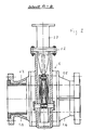
- Fig. 1 shows a pinch valve in a cross section perpendicular to the hose axis.
- Fig. 2 shows a pinch valve in a cross section which runs in a plane running through the hose axis and parallel to the closing direction.
- Fig. 3 shows a hose according to the invention in a crimped state.
- FIG. 4 shows the hose according to FIG. 3 with a maximum cross section.
- the pinch valve shown in FIG. 1 has a housing 1, with a lower housing part 1.1 and a cover 1.2. In a symmetrical arrangement, two crimping arms 2.1, 2.1 are provided. Furthermore, a drive is provided, which is not shown here.
- a transmission mechanism comprises a push rod 3.1, a yoke 3.2 fastened to this at the bottom, and a scissor grille which comprises the double levers 3.3, 3.4 and four joints 3.5, 3.6, 3.7 and 3.8.
- pipe sockets are screwed onto the actual housing 1 on both sides. These pipe sockets are each divided in a horizontal plane that runs through the hose axis, so that a total of four pipe socket halves 1.3, 1.4, 1.5 and 1.6 are present.
- a guide attachment 1.7 is screwed onto the housing cover 1.2 and is used to guide the push rod 3.1.
- the two scissor grids are each articulated at the outer end of the double lever 3.4 by means of a joint 3.6 on the lower housing part 1.1, and in so far as it is stationary with respect to the housing 1.
- the two lower, free ends of the yoke 3.2 act on the outer end of the double lever 3.3 by means of a joint 3.5.
- the other two ends - the ends facing the hose 4 - attack each of the two brackets 2.1.
- Joint 3.8 is stationary with respect to bracket 2.1, however joint 3.7, and thus the relevant end of double lever 3.4, is displaceable with respect to bracket 2.1.
- the displacement takes place in the longitudinal direction of the bracket 2.1.
- a dash-dotted line 2.2 indicates an elongated hole in which a pin of the joint 3.7 can slide up and down.
- the hose when squeezed together, has a cross section that resembles an elongated rectangle over most of its length except for the two end regions.
- the end areas have approximately the shape of an ellipse.
- the small axis of the ellipse is slightly larger than the width of the rectangle.
- one pinch bracket could be absolutely stationary, i.e. not be movable, only the other be moved in the closing direction.
- the scissor lattice could have a different transmission range than the one mentioned at the beginning from 1: 2 to 2: 1.
- two double levers per scissor grid several scissor grids could be provided.
- a housing is not absolutely necessary. The housing could also be completely open on one side, for example from below, or easily openable, for example for maintenance purposes.
Landscapes
- Engineering & Computer Science (AREA)
- General Engineering & Computer Science (AREA)
- Mechanical Engineering (AREA)
- Mechanically-Actuated Valves (AREA)
- Pipe Accessories (AREA)
- Lift Valve (AREA)
- Feeding And Controlling Fuel (AREA)
- Rigid Pipes And Flexible Pipes (AREA)
Description
- Die Erfindung betrifft ein Quetschventil zum Absperren eines Schlauches.
- Derartige Ventile sind in großer Zahl und in vielfältiger Ausführung bekanntgeworden.
- Ein solches Ventil weist im allgemeinen ein Gehäuse auf, das den Schlauch oben schließt, ferner zwei Bügel, die im wesentlichen parallel zueinander angeordnet sind, und die zum Zwecke des Zusammenquetschens bzw. Wiederfreigebens des Schlauches zusammengefahren bzw. wieder auseinandergefahren werden können. Weiterhin ist bei einem solchen Ventil ein Antrieb vorgesehen sowie ein Übertragungsmechanismus zum Übertragen der Quetschkraft vom Antrieb auf einen der beiden Quetschbügel, oder auf beide Quetschbügel. Der Antrieb kann ein Handrad umfassen, und der Übertragungsmechanismus eine Gewindespindel. Stattdessen kann auch ein pneumatischer oder hydraulischer Antrieb mit Druckzylinder, Kolben und Kolbenstange vorgesehen sein.
- Die genannten Quetschbügel müssen beim Öffnen oder Schließen derart geführt werden, daß sie mit ihren dem Schlauch zugewandten Quetschflächen planparallel verlaufen; die Quetschflächen müssen somit bei Betrieb des Quetschventils eine Parallelverschiebung zueinander ausführen. Zu diesem Zwecke müssen die Bügel in Verschieberichtung geführt werden. Hierzu dienen beispielsweise Führungsstangen, die am Gehäuse befestigt sind, und die durch Bohrungen in den Quetschbügeln hindurch geführt sind. Die entsprechenden Führungselemente müssen bearbeitet werden, was einen erheblichen Aufwand darstellt.
- Das gleiche gilt dann, wenn das Quetschventil gehäuselos ausgeführt ist. Auch in diesem Falle müssen Führungselemente vorgesehen werden, also beispielsweise Führungsstangen, in denen wiederum die Führungsbügel laufen.
- Ein weiterer Nachteil der bekannten Quetschventile besteht darin, daß die beim Schließvorgang vom Antrieb aufzubringende Kraft mit zunehmendem Abquetschen des Schlauches ansteigt. Handelt es sich um einen motorischen Antrieb, so muß dessen Leistung dem maximalen Kraftaufwand angepaßt sein.
- FR-A-2231916 beschreibt ein Rohrquetschgerät mit den Merkmalen des Oberbegriffes von Anspruch 1.
- Der Erfindung liegt die Aufgabe zugrunde, ein Quetschventil gemäß dem Oberbegriff von Anspruch 1 zu schaffen, das im Aufbau einfacher als die bisher bekannten Quetschventile ist, das insbesondere weniger Teile mit bearbeiteten Flächen aufweist, dessen Antriebsleistung nicht durch die maximale, beim Schließvorgang aufzubringende Kraft bestimmt ist, das bedienungsfreundlich ist, und das leicht demontierbar ist.
- Diese Aufgabe wird durch die kennzeichnenden Merkmale von Anspruch 1 gelöst.
- Hierdurch wird im einzelnen folgendes erreicht:
- Das Gehäuse des Ventils braucht keine Führungsflächen aufzuweisen, die bearbeitet werden müssen. Der Übertragungsmechanismus - nämlich das Scherengitter - kann im geschlossenen Gehäuse angeordnet werden. Somit ist es gegen Verschmutzung geschützt. Im Normalfall besteht kein Anlaß, das Gehäuse aufzumachen, und den Übertragungsmechanismus, nämlich das Scherengitter, zu warten. Ein ganz besonderer Vorteil des Quetschventils gemäß der Erfindung besteht darin, daß die Schließkraft über den gesamten Schließweg im wesentlichen gleich groß ist. Das Übersetzungsverhältnis der Scheren beträgt zu Beginn des Schließvorganges in einem konkreten Falle 1 : 2, und kurz vor dem Schließzustand 2 : 1. Dieses Übersetzungsverhältnis ist genau proportional dem Widerstand von Schlauch und Schlauch-Innendruck.
- Die maximale Schließkraft kurz vor dem Schließen erreicht durch das Übersetzungsverhältnis von 2 : 1 nur die Hälfte des Wertes herkömmlicher Armaturen. Deshalb kann auch der Antrieb - Handrad, pneumatischer Antrieb, hydraulischer Antrieb, elektromotorischer Antrieb - klein ausgelegt werden.
- Gemäß einem weiteren Gedanken der Erfindung wird dem Schlauch ein ganz bestimmtes Querschnittsprofil gegeben, so daß bei einer bestimmten Anzahl von Schließ- und Öffnungsintervallen die Lebensdauer des Schlauches gesteigert werden kann, wodurch sich der Bedienungskomfort steigern und die Wartungskosten senken lassen.
- Die Erfindung ist anhand der Zeichnung näher erläutert. Darin ist im einzelnen folgendes dargestellt:
- Fig. 1 zeigt ein Quetschventil in einem zur Schlauchachse senkrechten Querschnitt.
- Fig. 2 zeigt ein Quetschventil in einem Querschnitt, das in einer durch die Schlauchachse verlaufenden, zur Schließrichtung parallelen Ebene verläuft.
- Fig. 3 zeigt einen erfindungsgemäßen Schlauch in zusammengequetschtem Zustand.
- Fig. 4 zeigt den Schlauch gemäß Fig. 3 bei maximalem Durchschlußquerschnitt.
- Das in Fig. 1 gezeigte Quetschventil weist ein Gehäuse 1 auf, mit einem Gehäuseunterteil 1.1 und einem Deckel 1.2. In einer symmetrischen Anordnung sind zwei Quetschbügel 2.1, 2.1 vorgesehen. Ferner ist ein Antrieb vorgesehen, der hier nicht dargestellt ist.
- Ein Übertragungsmechanismus umfaßt eine Schubstange 3.1, ein an dieser unten befestigtes Joch 3.2, sowie ein Scherengitter, das die Doppelhebel 3.3, 3.4 sowie vier Gelenke 3.5, 3.6, 3.7 und 3.8 umfaßt.
- Man erkennt ferner aus Fig. 1 den Schlauch 4 des Quetschventils. Die linke Hälfte dieser Figur zeigt die Schließstellung, während die rechte Hälfte die Stellung des maximalen Durchschlußquerschnittes darstellt.
- Wie man aus Fig. 2 erkennt, sind am eigentlichen Gehäuse 1 beidseits Rohrstutzen angeschraubt. Diese Rohrstutzen sind in einer Horizontalebene, die durch die Schlauchachse verläuft, jeweils geteilt, so daß insgesamt vier Rohrstutzenhälften 1.3, 1.4, 1.5 und 1.6 vorhanden sind. Auf dem Gehäusedeckel 1.2 ist ein Führungsaufsatz 1.7 aufgeschraubt, der zum Führen der Schubstange 3.1 dient.
- Die beiden Scherengitter sind jeweils am äußeren Ende des Doppelhebels 3.4 mittels Gelenk 3.6 am Gehäuse-Unterteil 1.1 angelenkt, und in soweit in Bezug auf das Gehäuse 1 ortsfest. Die beiden unteren, freien Enden des Joches 3.2 greifen mittels Gelenk 3.5 am äußeren Ende des Doppelhebels 3.3 an. Die beiden anderen Enden - die dem Schlauch 4 zugewandten Enden - greifen jeweils an einem der beiden Bügel 2.1 an. Dabei ist Gelenk 3.8 in Bezug auf den Bügel 2.1 ortsfest, jedoch ist Gelenk 3.7, und damit auch das diesbezügliche Ende von Doppelhebel 3.4, in Bezug auf den Bügel 2.1 verschiebbar. Die Verschiebung erfolgt in Längsrichtung der Bügel 2.1. Eine strichpunktierte Linie 2.2 deutet ein Langloch an, in welchem ein Bolzen des Gelenkes 3.7 auf- und ab gleiten kann.
- Wie man erkennt, arbeitet das Ventil wie folgt:
- Wird mittels des (nicht dargestellten) Antriebes auf das zunächst geöffnete Quetschventil von oben her eine Kraft auf die Schubstange 3.1 ausgeübt, so wird diese Kraft mittels des Joches 3.2 über Gelenk 3.5 auf den Doppelhebel 3.3 übertragen. Die Schere schließt sich, indem das Gelenk 3.5 sowie auch das Gelenk 3.7 nach unten gedrückt wird und gleichzeitig wird der betreffende Bügel 2.1 in Schließrichtung bewegt.
- Von besonderem Interesse ist die Gestaltung des Querprofiles des Schlauches 4. Wie man aus Fig. 3 erkennt, weist der Schlauch in zusammengequetschtem Zustand einen Querschnitt auf, der über den größten Teil seiner Länge bis auf die beiden Endbereiche einem langgestrecktem Rechteck gleicht. Die Endbereiche haben annähernd die Form einer Ellipse. Dabei ist die kleine Achse der Ellipse etwas größer, als die Breite des Rechteckes.
- Im nicht-gequetschten Zustand gemäß Fig. 4 erkennt man im Bereich der Quetschebene jeweils wulstartige Verdickungen des Schlauches. Man beachte die Außenkontur im Bereich der horizontal verlaufenden Quetschebene. Diese ist dadurch entstanden, daß an dieser Stelle der Kreiskontur eine einzige, kuppenartige Kontur aufgesetzt wurde. Die Innenkontur weicht ebenfalls von der Kreiskontur ab, und zwar dadurch, daß jeweils oberhalb und unterhalb der horizontalen Quetschebene je eine weitere kuppenartige Kontur aufgesetzt wurde.
- Von allen möglichen, im Rahmen der Erfindung liegenden Abwandlungen kommt z.B. in Betracht, das Quetschventil asymmetrisch auszubilden. Femer könnte der eine Quetschbügel absolut ortsfest, d.h. nicht beweglich sein, sondern nur der andere in Schließrichtung bewegt werden. Das Scherengitter könnte einen anderen Übersetzungsbereich als den eingangs genannten von 1: 2 bis 2 : 1 aufweisen. Statt zweier Doppelhebel pro Scherengitter könnten mehrere Scherengitter vorgesehen werden. Im Extremfalle bedarf es nicht unbedingt eines Gehäuses. Auch könnte das Gehäuse auf einer Seite, beispielsweise von unten her, völlig offen oder leicht öffenbar sein, beispielsweise für Wartungszwecke.
Claims (6)
- Quetschventil zum Absperren eines Schlauches (4);1.1 mit einem Bügel und einem Gegenbügel (2.1; 2.1) zum Zusammenquetschen des Schlauches;1.2 mit einem Antrieb (3.1);1.3 mit einem zwischen Antrieb (3.1) und Bügel (2.1; 2.1) geschalteten Übertragungsmechanismus (3)1.4 der Übertragungsmechanismus (3) umfaßt wenigstens ein Scherengitter mit wenigstens zwei Doppelhebeln (3.3, 3.4);1.5 ein Doppelhebel (3.4) des Scherengitters ist an einem von dem betreffenden Bügel (2.1) fernen Punkt ortsfest angelenkt;1.6 der Antrieb greift mittelbar oder unmittelbar an einem anderen Doppelhebel (3.3) des Scherengitters an, dadurch gekennzeichnet daß jedem Bügel (2.1;2.1) ein Scherengitter zugeordnet ist.
- Quetschventil nach Anspruch 1, dadurch gekennzeichnet, daß ein Gehäuse (1) vorgesehen ist, das den Übertragungsmechanismus (3) sowie die Bügel (2.1, 2.1) mit dem zusammenzuquetschenden Schlauchabschnitt umschließt.
- Quetschventil nach Anspruch 1 oder 2, dadurch gekennzeichnet, daß die Quetschebene in Bewegungsrichtung des Antriebes verläuft.
- Scherengitter nach einem der Ansprüche 1-3, dadurch gekennzeichnet, daß der Übertragungsmechanismus in Bezug auf die Quetschebene symmetrisch ausgeführt ist.
- Quetschventil nach einem der Ansprüche 1-4, gekennzeichnet durch die folgenden Merkmale:5.1 Die einem Bügel (2.1) am nächsten liegenden Doppelhebelenden zweier einander zugeordneter Doppelhebel sind an diesem Bügel (2.1) angelenkt;5.2 das eine Gelenk (3.8) ist in Bezug auf diesen Bügel (2.1) ortsfest, während das andere Gelenk (3.7) an diesem Bügel (2.1) senkrecht zur Quetschrichtung zu gleiten vermag.
- Quetschventil, nach einem der Ansprüche 1-5, dadurch gekennzeichnet daß es einen Schlauch aufweist mit der folgenden Querschnittsform:6.1 der Schlauch weist in zusammengequetschem Zustand die Gestalt eines langgestreckten Rechteckes auf, bis auf seine beiden Endbereiche;6.2 die beiden Endbereiche haben wenigstens annähernd jeweils die Gestalt einer Ellipse, wobei die kleine Achse der Ellipse wenigstens geringfügig größer als die Breite des Rechteckes ist;6.3 im Zustand maximalen Durchflußquerschnittes ist die Außenkontur des Schlauches (4) gegenüber der Kreiskontur durch einen einzigen, in Quetschebene liegenden, kuppenartigen Wulst verdickt, und die Innenkontur durch zwei kuppenartige Wulste, die jeweils unmittelbar vor der Quetschebene liegen.
Applications Claiming Priority (2)
| Application Number | Priority Date | Filing Date | Title |
|---|---|---|---|
| DE4326449 | 1993-08-06 | ||
| DE4326449A DE4326449A1 (de) | 1993-08-06 | 1993-08-06 | Quetschventil zum Absperren eines Schlauches |
Publications (2)
| Publication Number | Publication Date |
|---|---|
| EP0637707A1 EP0637707A1 (de) | 1995-02-08 |
| EP0637707B1 true EP0637707B1 (de) | 1996-10-23 |
Family
ID=6494612
Family Applications (1)
| Application Number | Title | Priority Date | Filing Date |
|---|---|---|---|
| EP94110691A Expired - Lifetime EP0637707B1 (de) | 1993-08-06 | 1994-07-09 | Quetschventil zum Absperren eines Schlauches |
Country Status (3)
| Country | Link |
|---|---|
| EP (1) | EP0637707B1 (de) |
| AT (1) | ATE144598T1 (de) |
| DE (2) | DE4326449A1 (de) |
Families Citing this family (13)
| Publication number | Priority date | Publication date | Assignee | Title |
|---|---|---|---|---|
| US6289912B1 (en) * | 1998-07-10 | 2001-09-18 | Fluoroware, Inc. | Pinch element plastic valve |
| ATE314596T1 (de) | 2000-07-11 | 2006-01-15 | Arno Drechsel | Ventil |
| CA2451928C (en) | 2002-12-04 | 2007-09-18 | Tom Ball | A flow-regulating device |
| WO2006066489A1 (fr) * | 2004-12-23 | 2006-06-29 | Pan, Shijun | Valve a double étanchéité |
| KR100886871B1 (ko) | 2007-05-21 | 2009-03-05 | 정년구 | 핀치밸브 |
| DE102007025850B3 (de) * | 2007-06-01 | 2008-05-08 | Sim Automation Gmbh & Co.Kg | Prüfeinrichtung für gasdurchströmte Bauteile |
| CN102155575B (zh) * | 2011-04-11 | 2012-09-05 | 上海曹杨建筑粘合剂厂 | 一种剪刀阀 |
| DE102011055850B3 (de) * | 2011-11-30 | 2012-11-29 | Sartorius Weighing Technology Gmbh | Quetschventil |
| CN103671987A (zh) * | 2012-09-18 | 2014-03-26 | 昆山尚达智机械有限公司 | 一种方便开合的阀门 |
| DE102020121357B3 (de) | 2020-08-13 | 2021-08-12 | Sartorius Stedim Systems GmbH | Gehäuse |
| CN115031036B (zh) * | 2021-03-03 | 2025-07-15 | 广东博智林机器人有限公司 | 阀门装置及混合设备 |
| CN114017576B (zh) * | 2021-11-02 | 2023-03-10 | 深州市建投燃气有限公司 | 一种聚乙烯燃气管道止气卡管器 |
| KR102836987B1 (ko) * | 2023-05-02 | 2025-07-23 | 주식회사 디엠에스 | 링크방식의 복원수단이 구비된 핀치밸브 |
Family Cites Families (3)
| Publication number | Priority date | Publication date | Assignee | Title |
|---|---|---|---|---|
| DE1038850B (de) * | 1954-10-25 | 1958-09-11 | Herwarth Reich Dipl Ing | Schlauchklemmventil |
| FR2231916A1 (en) * | 1973-06-04 | 1974-12-27 | Fournier Henri | Tube flow cut off device for use during fires - tube is crushed by pair of jaws held parallel by linkage |
| US5297773A (en) * | 1993-07-16 | 1994-03-29 | Fluoroware, Inc. | Plastic valve with flexible tube and tube squeezing apparatus |
-
1993
- 1993-08-06 DE DE4326449A patent/DE4326449A1/de not_active Withdrawn
-
1994
- 1994-07-09 EP EP94110691A patent/EP0637707B1/de not_active Expired - Lifetime
- 1994-07-09 AT AT94110691T patent/ATE144598T1/de not_active IP Right Cessation
- 1994-07-09 DE DE59400883T patent/DE59400883D1/de not_active Expired - Fee Related
Also Published As
| Publication number | Publication date |
|---|---|
| DE59400883D1 (de) | 1996-11-28 |
| EP0637707A1 (de) | 1995-02-08 |
| DE4326449A1 (de) | 1995-02-09 |
| ATE144598T1 (de) | 1996-11-15 |
Similar Documents
| Publication | Publication Date | Title |
|---|---|---|
| DE69217301T2 (de) | Verfahren und Vorrichtung zum Steuern ein Flüssigkeitsströmung | |
| DE2435912C2 (de) | Folge-Quetschventil | |
| DE2611571A1 (de) | Fluiddruckgesteuerter ventilaufbau | |
| DE3423283A1 (de) | Klemmwerkzeug, insbesondere zum verbinden von rohren und anderen profilen | |
| DE3519203A1 (de) | Stellvorrichtung fuer eine tuer eines kraftfahrzeugs | |
| EP0637707A1 (de) | Quetschventil zum Absperren eines Schlauches | |
| DE2535315A1 (de) | Komprimiervorrichtung | |
| DE4334424C2 (de) | Stangenloser Zylinder | |
| DE102010044327A1 (de) | Zentrierspannvorrichtung | |
| WO1997022821A1 (de) | Vorrichtung zum antrieb für doppelsitzventile | |
| EP0085852B1 (de) | 3/2-Wegeventil | |
| DE102007050353A1 (de) | Greifvorrichtung | |
| DE2825178C2 (de) | Steuerungsvorrichtung zum Betätigen eines Druck-Zugkabels | |
| DE102020129107A1 (de) | Verfahren zur Herstellung eines Vakuumspeichers für Warmwasser und Quetschwerkzeug zur Durchführung des Verfahrens | |
| DE3235040A1 (de) | Presse zum aufpressen von huelsen, kabelschuhen oder dergleichen | |
| DE3607975C2 (de) | Buchsenteil einer Rohr- oder Schlauchleitungskupplung | |
| DE2537794A1 (de) | Blindnietgeraet | |
| DE2431135B2 (de) | ||
| EP4171465B1 (de) | Klemmvorrichtung | |
| WO2024022787A1 (de) | Ventil | |
| DE706377C (de) | UEberdruckventil fuer Druckbehaelter von elektrischen Apparaten und Maschinen | |
| DE19926043B4 (de) | Verdrehsicherungseinrichtung | |
| DE69514161T2 (de) | Auf flachen biegsamen Gurten wirkende Zug- oder Hebevorrichtung mit Backen | |
| DE3508542A1 (de) | Wischarm | |
| DE3026550C2 (de) | Vorrichtung zum Öffnen und Schließen einer Tür, insbesondere einer Feuertür |
Legal Events
| Date | Code | Title | Description |
|---|---|---|---|
| PUAI | Public reference made under article 153(3) epc to a published international application that has entered the european phase |
Free format text: ORIGINAL CODE: 0009012 |
|
| AK | Designated contracting states |
Kind code of ref document: A1 Designated state(s): AT BE CH DE FR LI NL SE |
|
| 17P | Request for examination filed |
Effective date: 19950517 |
|
| 17Q | First examination report despatched |
Effective date: 19951220 |
|
| GRAG | Despatch of communication of intention to grant |
Free format text: ORIGINAL CODE: EPIDOS AGRA |
|
| GRAH | Despatch of communication of intention to grant a patent |
Free format text: ORIGINAL CODE: EPIDOS IGRA |
|
| GRAH | Despatch of communication of intention to grant a patent |
Free format text: ORIGINAL CODE: EPIDOS IGRA |
|
| GRAA | (expected) grant |
Free format text: ORIGINAL CODE: 0009210 |
|
| AK | Designated contracting states |
Kind code of ref document: B1 Designated state(s): AT BE CH DE FR LI NL SE |
|
| REF | Corresponds to: |
Ref document number: 144598 Country of ref document: AT Date of ref document: 19961115 Kind code of ref document: T |
|
| REF | Corresponds to: |
Ref document number: 59400883 Country of ref document: DE Date of ref document: 19961128 |
|
| ET | Fr: translation filed | ||
| PLBE | No opposition filed within time limit |
Free format text: ORIGINAL CODE: 0009261 |
|
| STAA | Information on the status of an ep patent application or granted ep patent |
Free format text: STATUS: NO OPPOSITION FILED WITHIN TIME LIMIT |
|
| 26N | No opposition filed | ||
| PGFP | Annual fee paid to national office [announced via postgrant information from national office to epo] |
Ref country code: AT Payment date: 19980629 Year of fee payment: 5 |
|
| PGFP | Annual fee paid to national office [announced via postgrant information from national office to epo] |
Ref country code: NL Payment date: 19980728 Year of fee payment: 5 |
|
| PGFP | Annual fee paid to national office [announced via postgrant information from national office to epo] |
Ref country code: CH Payment date: 19980819 Year of fee payment: 5 |
|
| PG25 | Lapsed in a contracting state [announced via postgrant information from national office to epo] |
Ref country code: AT Free format text: LAPSE BECAUSE OF NON-PAYMENT OF DUE FEES Effective date: 19990709 |
|
| PGFP | Annual fee paid to national office [announced via postgrant information from national office to epo] |
Ref country code: FR Payment date: 19990721 Year of fee payment: 6 |
|
| PGFP | Annual fee paid to national office [announced via postgrant information from national office to epo] |
Ref country code: SE Payment date: 19990726 Year of fee payment: 6 |
|
| PGFP | Annual fee paid to national office [announced via postgrant information from national office to epo] |
Ref country code: BE Payment date: 19990727 Year of fee payment: 6 |
|
| PG25 | Lapsed in a contracting state [announced via postgrant information from national office to epo] |
Ref country code: LI Free format text: LAPSE BECAUSE OF NON-PAYMENT OF DUE FEES Effective date: 19990731 Ref country code: CH Free format text: LAPSE BECAUSE OF NON-PAYMENT OF DUE FEES Effective date: 19990731 |
|
| PGFP | Annual fee paid to national office [announced via postgrant information from national office to epo] |
Ref country code: DE Payment date: 19990909 Year of fee payment: 6 |
|
| PG25 | Lapsed in a contracting state [announced via postgrant information from national office to epo] |
Ref country code: NL Free format text: LAPSE BECAUSE OF NON-PAYMENT OF DUE FEES Effective date: 20000201 |
|
| REG | Reference to a national code |
Ref country code: CH Ref legal event code: PL |
|
| NLV4 | Nl: lapsed or anulled due to non-payment of the annual fee |
Effective date: 20000201 |
|
| PG25 | Lapsed in a contracting state [announced via postgrant information from national office to epo] |
Ref country code: SE Free format text: LAPSE BECAUSE OF NON-PAYMENT OF DUE FEES Effective date: 20000710 |
|
| PG25 | Lapsed in a contracting state [announced via postgrant information from national office to epo] |
Ref country code: BE Free format text: LAPSE BECAUSE OF NON-PAYMENT OF DUE FEES Effective date: 20000731 |
|
| BERE | Be: lapsed |
Owner name: VERWALTUNGS LOHSE G.M.B.H. & CO. K.G. Effective date: 20000731 |
|
| EUG | Se: european patent has lapsed |
Ref document number: 94110691.6 |
|
| PG25 | Lapsed in a contracting state [announced via postgrant information from national office to epo] |
Ref country code: FR Free format text: LAPSE BECAUSE OF NON-PAYMENT OF DUE FEES Effective date: 20010330 |
|
| REG | Reference to a national code |
Ref country code: FR Ref legal event code: ST |
|
| PG25 | Lapsed in a contracting state [announced via postgrant information from national office to epo] |
Ref country code: DE Free format text: LAPSE BECAUSE OF NON-PAYMENT OF DUE FEES Effective date: 20010501 |