EP0634846A2 - Système de transmission de données pour la distribution de programmes audiovisuels dans un système de télédistribution - Google Patents
Système de transmission de données pour la distribution de programmes audiovisuels dans un système de télédistribution Download PDFInfo
- Publication number
- EP0634846A2 EP0634846A2 EP94305257A EP94305257A EP0634846A2 EP 0634846 A2 EP0634846 A2 EP 0634846A2 EP 94305257 A EP94305257 A EP 94305257A EP 94305257 A EP94305257 A EP 94305257A EP 0634846 A2 EP0634846 A2 EP 0634846A2
- Authority
- EP
- European Patent Office
- Prior art keywords
- terminal
- request
- mode
- information data
- transmission
- Prior art date
- Legal status (The legal status is an assumption and is not a legal conclusion. Google has not performed a legal analysis and makes no representation as to the accuracy of the status listed.)
- Withdrawn
Links
Images


Classifications
-
- H—ELECTRICITY
- H04—ELECTRIC COMMUNICATION TECHNIQUE
- H04N—PICTORIAL COMMUNICATION, e.g. TELEVISION
- H04N7/00—Television systems
- H04N7/16—Analogue secrecy systems; Analogue subscription systems
- H04N7/173—Analogue secrecy systems; Analogue subscription systems with two-way working, e.g. subscriber sending a programme selection signal
- H04N7/17309—Transmission or handling of upstream communications
-
- G—PHYSICS
- G10—MUSICAL INSTRUMENTS; ACOUSTICS
- G10H—ELECTROPHONIC MUSICAL INSTRUMENTS; INSTRUMENTS IN WHICH THE TONES ARE GENERATED BY ELECTROMECHANICAL MEANS OR ELECTRONIC GENERATORS, OR IN WHICH THE TONES ARE SYNTHESISED FROM A DATA STORE
- G10H1/00—Details of electrophonic musical instruments
- G10H1/0033—Recording/reproducing or transmission of music for electrophonic musical instruments
- G10H1/0041—Recording/reproducing or transmission of music for electrophonic musical instruments in coded form
- G10H1/0058—Transmission between separate instruments or between individual components of a musical system
-
- H—ELECTRICITY
- H04—ELECTRIC COMMUNICATION TECHNIQUE
- H04H—BROADCAST COMMUNICATION
- H04H20/00—Arrangements for broadcast or for distribution combined with broadcast
- H04H20/38—Arrangements for distribution where lower stations, e.g. receivers, interact with the broadcast
-
- H—ELECTRICITY
- H04—ELECTRIC COMMUNICATION TECHNIQUE
- H04H—BROADCAST COMMUNICATION
- H04H20/00—Arrangements for broadcast or for distribution combined with broadcast
- H04H20/65—Arrangements characterised by transmission systems for broadcast
- H04H20/76—Wired systems
- H04H20/77—Wired systems using carrier waves
- H04H20/78—CATV [Community Antenna Television] systems
- H04H20/79—CATV [Community Antenna Television] systems using downlink of the CATV systems, e.g. audio broadcast via CATV network
-
- H—ELECTRICITY
- H04—ELECTRIC COMMUNICATION TECHNIQUE
- H04H—BROADCAST COMMUNICATION
- H04H60/00—Arrangements for broadcast applications with a direct linking to broadcast information or broadcast space-time; Broadcast-related systems
- H04H60/76—Arrangements characterised by transmission systems other than for broadcast, e.g. the Internet
- H04H60/81—Arrangements characterised by transmission systems other than for broadcast, e.g. the Internet characterised by the transmission system itself
- H04H60/93—Wired transmission systems
- H04H60/96—CATV systems
- H04H60/97—CATV systems using uplink of the CATV systems
-
- H—ELECTRICITY
- H04—ELECTRIC COMMUNICATION TECHNIQUE
- H04N—PICTORIAL COMMUNICATION, e.g. TELEVISION
- H04N21/00—Selective content distribution, e.g. interactive television or video on demand [VOD]
- H04N21/40—Client devices specifically adapted for the reception of or interaction with content, e.g. set-top-box [STB]; Operations thereof
- H04N21/47—End-user applications
- H04N21/472—End-user interface for requesting content, additional data or services; End-user interface for interacting with content, e.g. for content reservation or setting reminders, for requesting event notification, for manipulating displayed content
-
- H—ELECTRICITY
- H04—ELECTRIC COMMUNICATION TECHNIQUE
- H04N—PICTORIAL COMMUNICATION, e.g. TELEVISION
- H04N21/00—Selective content distribution, e.g. interactive television or video on demand [VOD]
- H04N21/60—Network structure or processes for video distribution between server and client or between remote clients; Control signalling between clients, server and network components; Transmission of management data between server and client, e.g. sending from server to client commands for recording incoming content stream; Communication details between server and client
- H04N21/65—Transmission of management data between client and server
- H04N21/658—Transmission by the client directed to the server
- H04N21/6581—Reference data, e.g. a movie identifier for ordering a movie or a product identifier in a home shopping application
-
- H—ELECTRICITY
- H04—ELECTRIC COMMUNICATION TECHNIQUE
- H04N—PICTORIAL COMMUNICATION, e.g. TELEVISION
- H04N21/00—Selective content distribution, e.g. interactive television or video on demand [VOD]
- H04N21/80—Generation or processing of content or additional data by content creator independently of the distribution process; Content per se
- H04N21/81—Monomedia components thereof
- H04N21/8126—Monomedia components thereof involving additional data, e.g. news, sports, stocks, weather forecasts
- H04N21/8133—Monomedia components thereof involving additional data, e.g. news, sports, stocks, weather forecasts specifically related to the content, e.g. biography of the actors in a movie, detailed information about an article seen in a video programme
-
- G—PHYSICS
- G10—MUSICAL INSTRUMENTS; ACOUSTICS
- G10H—ELECTROPHONIC MUSICAL INSTRUMENTS; INSTRUMENTS IN WHICH THE TONES ARE GENERATED BY ELECTROMECHANICAL MEANS OR ELECTRONIC GENERATORS, OR IN WHICH THE TONES ARE SYNTHESISED FROM A DATA STORE
- G10H2240/00—Data organisation or data communication aspects, specifically adapted for electrophonic musical tools or instruments
- G10H2240/171—Transmission of musical instrument data, control or status information; Transmission, remote access or control of music data for electrophonic musical instruments
- G10H2240/201—Physical layer or hardware aspects of transmission to or from an electrophonic musical instrument, e.g. voltage levels, bit streams, code words or symbols over a physical link connecting network nodes or instruments
- G10H2240/265—CATV transmission, i.e. electrophonic musical instruments connected to community antennas or cable television networks
Definitions
- the present invention relates to a data transmission system wherein a central control unit and a plurality of terminals are connected by a transmission line, the data transmission system being for transmitting information data from the central control unit to the terminals.
- a data transmission system wherein a center (central control unit) is connected to a plurality of terminals by a transmission line.
- the data transmission system is for transmitting information data including various types of information to a terminal from a center according to demands from the terminal side.
- transmission and reception of the information data is controlled by polling between the center and the terminal. That is, a polling signal is transmitted in succession from the center to the plurality of terminals. Every terminal is interrogated to determine which requests transmission of information data.
- the request data which indicates the content and the like of the request, is transmitted from the terminal to the center. After the signal has been received at the center side, the desired information data is transmitted to the terminal.
- an object of the present invention to overcome the above-described problems and to provide a data transmission system wherein a terminal can obtain desired information data with a short waiting time.
- the present invention provides a data transmission system for controlling transmission of information data via a transmission line from a central control unit to a plurality of terminals, the data transmission system comprising: a central control unit; and a plurality of terminals connected to said central control unit via a transmission line, wherein said central control unit includes mode sense polling signal transmission means for transmitting a mode sense polling signal, via the transmission line, to each of the plurality of terminals for confirming an operation mode of each terminal; wherein each of said plurality of terminals includes mode response signal transmission means for transmitting, in response to the mode sense polling signal, a mode response signal indicating a present operation mode of the each terminal to said central control unit via the transmission line, wherein said central control unit further includes: determination means for determining the operation mode of each terminal, based on the mode response signal transmitted from each terminal; and request polling signal transmission means for selectively transmitting a request polling signal to a terminal that is determined by the determination means to be in the predetermined operation mode for detecting whether the terminal requests transmission of information data
- the present invention provides a data transmission device for transmitting information data via a transmission line to a plurality of terminals, upon requested by the plurality of terminals, the data transmission device comprising: mode sense polling signal transmission means for transmitting a mode sense polling signal to each of a plurality of terminals connected to the data transmission device via a transmission line, to thereby detect an operation mode of the each terminal; request polling signal transmission means for selectively transmitting a request polling signal to a terminal that is detected by said mode sense polling signal to be in a predetermined operation mode, to thereby detect whether or not the terminal requests transmission of information data; and information data transmission means for transmitting the information data to the terminal that is detected by said request polling signal transmission means to request the transmission of the information data.
- the present invention provides a method of controlling transmission of information data via a transmission line from a central control unit to a plurality of terminals, the plurality of terminals being connected to the central control unit via the transmission line, the method comprising the steps of: transmitting a mode sense polling signal from a central control unit via a transmission line to each of a plurality of terminals for confirming an operation mode of each terminal; transmitting, from each terminal to the central control unit via the transmission line, a mode response signal indicating a present operation mode of the each terminal, in response to the mode sense polling signal; determining the operation mode of each terminal, based on the mode response signal transmitted from each terminal; selectively transmitting a request polling signal from the central control unit to a terminal that is determined to be in the predetermined operation mode for detecting whether the terminal requests transmission of information data; transmitting, from the terminal that has received the request polling signal to the central control unit, a request response signal indicating whether or not the terminal requests the transmission of information data, in response to the
- a central control unit M1 and a plurality of terminals M2 are connected by a transmission line.
- the data transmission system is for transmitting information data (including image information and/or sound information) from the central control unit M1 to the terminals M2 that have requested the transmission of the information data.
- the central control unit includes a mode sense polling signal transmission unit M3 for transmitting to all the terminals M2 mode sense polling signals for confirming respective operation mode of the terminals.
- Each terminal M2 includes a mode response signal transmission unit M4 for transmitting a mode response signal indicating the present operation mode of the each terminal to the central control unit M1, in response to the mode sense polling signal transmitted from the central control unit M1.
- the central control unit M1 further includes: a determination unit M5 for determining the present operation mode of each terminal M2 based on the mode response signals transmitted from the each terminal M2; and a selection unit M6 for selectively transmitting request polling signals to the terminals M2 depending on the operation mode of the terminals determined by the determination unit M5 so as to confirm requests for transmission of information data.
- the terminals M2 transmit information data request signals to the central control unit M1.
- the central control unit M1 transmits the information data to the terminals M2 that have requested the transmission of the information data.
- the central control unit M1 and the plurality of terminals M2 are connected by the transmission line.
- the mode sense polling signal transmission unit M3 of the central control unit M1 transmits to each terminal M2 a mode sense polling signal for confirming operation mode of the terminal M2.
- the mode response signal transmission unit M4 of each terminals M2 transmits, in response to the mode sense polling signal, a mode response signal indicating its own present operation mode to the central control unit M1.
- the determination unit M5 in the central control unit M1 determines the operation mode of each terminal M2 based on the mode response signal transmitted from the terminal M2.
- the selection unit M6 in the central control unit M1 selects whether or not to transmit a request polling signal to the terminal M2 depending on the operation mode determined by the determination unit M5.
- the central control unit M1 then transmits the request polling signals to the selected terminals M2 for confirming that the terminals M2 have requested transmission of information data.
- the terminals M2 transmit the information data request signals to the central control unit M1. Based on information data request signals, the central control unit transmits information data to the terminals M2.
- the central control unit M1 can determine not to transmit request polling signals to terminals M2 that are now set to operation modes where information data is not needed. Therefore, the number of terminals M2 to which request polling signals are transmitted can be reduced and wasted polling time can be eliminated. Accordingly, the waiting time until a request polling signal is received at a terminal is reduced and desired information can be obtained in a short waiting time.
- FIG. 2 A concrete example of the above-described data transmission device of the present invention will be described below with reference to Figs. 2 through 8.
- This example is a karaoke system to which applied is the above-described embodiment of the present invention.
- a plurality of karaoke terminals and a center (central control unit) are connected by a transmission line.
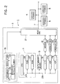
- the karaoke system 1 is constructed from a center 3 connected to a plurality of karaoke terminals 5 by a coaxial cable 7 (transmission line).
- the terminals 5 can be provided in separate buildings or in separate shops or booths within the same building.
- the center 3 includes a server (control portion) 11 for performing overall control of the center 3; a memory device 13 in which karaoke song data are stored; a center modem 15; background image output devices (VDP) 17a and 17b; broadcast satellite reception system 19; a head end 21, etc.
- the server 11 includes well-known components such as a central processing unit (CPU) 23, a ROM 25, and a RAM 27.
- a busline 29 is provided for connecting the server 11 to the memory device 13, an input/output interface (I/O) 31, the background image output devices 17a and 17b, and the like.
- I/O input/output interface
- the RAM 27 stores a mode management table for indicating a present operation mode of each of the plurality of terminals 5.
- the server 11 is for producing a mode sense polling signal and a request polling signal.
- the mode sense polling signal is a signal for confirming an operation mode of each terminal 5.
- the request polling signal is a signal for confirming whether a request for transmission of karaoke song data is present at each terminal that is in the karaoke mode.
- the server 11 produces a mode sense polling signal added with an address code corresponding to each of the plurality of terminals 5. More specifically, if the total number of the terminals 5 connected to the center 3 is N (integer more than 1), each of the terminals is numbered at a terminal number n (n is an integer number: 1 ⁇ n ⁇ N). The server 11 produces the N total number of mode sense polling signals, each of which is added with an address code indicating the terminal number n. Accordingly, when a mode sense polling signal is transmitted via the transmission line to the plurality of karaoke terminal 5, each karaoke terminal 5 refers to this address code to determine whether the mode sense polling is for itself.
- the server 11 produces a request polling signal added with an address code indicating the terminal number n. Accordingly, when a request polling signal is transmitted via the transmission line to the plurality of karaoke terminal 5, each karaoke terminal 5 refers to this address code to determine whether the mode sense polling is for itself.
- a large-capacity memory device such as a hard disk or an optical magnetic disk, is used in the memory device 13.
- Several thousand songs worth of karaoke song data are stored in the memory device 13.
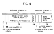
- one song worth of karaoke song data D1 includes: a synchronization signal D3; song number data D5 that indicates the song number; song content data D7; and partition data D9 for indicating the end of the one song worth of karaoke song data.
- the song content data D7 includes lyric data, for being projected on a monitor television of the terminal 5 (to be described later), and instrumental or vocal accompaniment data, for being played by a sound source of the terminal 5 (to be described later). It is noted that the accompaniment data is MIDI (Musical Instrument Digital Interface) standard data.
- the center modem 15 is for modulating karaoke song data retrieved from the memory device 13, mode sense polling signals and request polling signals outputted from the server 11, and the like into alternating current signals of a predetermined same channel (that is, a predetermined same frequency band), and then outputting the alternating current signals to the head end 21.
- the background image output devices (video disk players) 17a and 17b are for outputting background image data (video signals according to standard National Television System Committee (NTSC) system) for projecting on the monitor television of the terminal 5 (to be described later).
- the background image data are categorized according to genre of karaoke songs requestable by the terminals 5.
- one output device 17a may store image data directed toward Japanese ballads
- the other output device 17b may be store image data directed toward popular songs.
- Each of background image output devices 17a and 17b is connected to an individual modulator 33.
- the background image data outputted from the output devices 17a and 17b are modulated by the corresponding modulators 33 into alternating current signals of channels (frequency bands) different from each other.
- the alternating current signals of the different channels are inputted to the head end 21.
- the channels for the background image data are different from the channel over which the karaoke song data, the mode sense polling signals and the request polling signals are transmitted. It is further noted that each of the devices 17a and 17b always outputs the background image data. Accordingly, the background image data are always transmitted to the terminals 5.
- the broadcast satellite reception system 19 includes a reception antennae 35, a broadcast satellite tuner 37, and a modulator 39.
- the modulator 39 is connected to the head end 21.
- the tuner 37 outputs broadcast satellite signals including broadcast satellite image signals and broadcast satellite sound signals.
- the modulator 39 modulates the broadcast satellite signals from the tuner 37 into alternating current signals of a channel (frequency band) which is different from the channel (frequency band) over which the karaoke song data, the mode sense polling signals, and the request polling signals are transmitted and the channels (frequency bands) over which the background image data are transmitted. It is further noted that the tuner 37 always outputs the broadcast satellite signals. Accordingly, the broadcast satellite signals are always transmitted to the terminals 5.
- the head end 21 includes a variety of devices (not shown) such as a mixer for mixing signals inputted thereto and for outputting the mixed signals to the coaxial cable 7.
- a mixer for mixing signals inputted thereto and for outputting the mixed signals to the coaxial cable 7.
- Modulated signals of karaoke song data sent from the center modem 15; mode sense polling signals and request polling signals sent from the center modem 15; background image signals from the modulators 33; and broadcast satellite signals from the modulator 39 which have been modulated in different channels are inputted to the head end 21.
- the head end 21 multiplexes the plurality of different channel signals, and outputs them to the coaxial cable 7, along which the multiplexed signals are transmitted to the terminals 5.
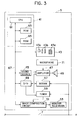
- each terminal 5 Next, an explanation of the structure of each terminal 5 will be provided while referring to Fig. 3.
- Each karaoke terminal 5 includes a control portion 41 for overall control of the terminal, an input device 43, a sound source 45, an amplifier 47, a speaker 49, an image composition circuit 51, a monitor television 53, a terminal modem 57 for receiving and processing the signals (the plurality of karaoke song data, the mode sense polling signals and the request polling signals) sent from the center 3, and a video tuner 59 for receiving and processing the signals (the background image data and the broadcast satellite signals) sent from the center 3.
- a control portion 41 for overall control of the terminal, an input device 43, a sound source 45, an amplifier 47, a speaker 49, an image composition circuit 51, a monitor television 53, a terminal modem 57 for receiving and processing the signals (the plurality of karaoke song data, the mode sense polling signals and the request polling signals) sent from the center 3, and a video tuner 59 for receiving and processing the signals (the background image data and the broadcast satellite signals) sent from the center 3.
- the control portion 41 includes a CPU 61, a ROM 63, and RAM 65 and is connected to the input device 43, the sound source 45, an input/output interface 69, the image composite circuit 51, and the like via a busline 67.
- the RAM 65 previously stores therein a song name/song genre information data indicating a genre of each of a plurality of karaoke songs requestable by the terminals 5. Examples of genre include Japanese ballads ( enka ) and popular songs, in this concrete example.
- the RAM also serves to temporarily store karaoke song data for a karaoke song requested at the input device 43 which has been transmitted from the center 3.
- the RAM 65 is formed with an operation mode table for storing the present operation mode of the corresponding terminal 5.
- the RAM 65 is also formed with a song number maintenance memory for storing the song number of a karaoke song requested by the input device 43.
- the control portion 41 is for producing a mode response signal and a request response signal.
- the mode response signal is a signal by which each terminal responds to the center 3 about its own operation mode in response to a mode sense polling signal from the center 3.
- the request response signal is a signal for responding to the center 3 about whether there is a request for a song (that is, a request for transmission of karaoke song data) in response to a request polling signal from the center 3.
- control portion 41 produces the mode response signal, referring to the operation mode table formed in the RAM 65.
- the mode response signal is added with data indicating the present operation mode of the corresponding terminal.
- the control portion 41 produces the request response signal, referring to the song number maintenance memory formed in the RAM 65. If a request has been made, the song number data of the requested karaoke song stored in the song number maintenance memory is attached to the request response signal.
- the input device 43 includes a variety of key switches by which a user operates the terminal 5. More specifically, the input device 43 includes a number pad (ten key) 43a for inputting song numbers of requested songs; mode keys 43b for selecting various operation modes; a power source switch 43c for turning the power source on and off; and the like.
- the operation modes of the terminal 5 include a karaoke mode for receiving karaoke song data transmitted from the center 3 and for performing karaoke; and a broadcast satellite mode for receiving a broadcast signal from the center 3 and allowing viewing of the satellite broadcast.
- the terminal modem 57 is for receiving and demodulating the karaoke song data, the mode sense polling signals, and the request polling signals that are transmitted from the center 3 via the coaxial cable 7.
- the terminal modem 57 also modulates signals, such as mode response signals and request response signals outputted from the control portion 41, and transmits them to the center 3. Processes for transmitting these signals will be described later.
- the video tuner 59 is for receiving the satellite broadcast signals, outputted from the broadcast signal system 19 and transmitted from the center 3, and the background image signals, outputted from the background image output devices 17a and 17b and transmitted from the center 3, and for selecting the channel of the desired image signal. That is, when the karaoke mode is designated as the operation mode using the mode key 43b of the input device 43, one of the channels over which the background image signals are transmitted is selected. When the broadcast satellite mode is designated as the operation mode using the mode key 43b of the input device 43, the channel over which the broadcast satellite signals are transmitted is selected.
- a microphone 71 is provided in each terminal 5 to produce a singing voice signal when a user sings into the microphone.
- the sound source (synthesizer sound source) 45 is for converting the MIDI data (accompaniment data), included in the karaoke song data shown in Fig. 4, into an analog karaoke accompaniment/sound signal.
- the amplifier 47 is for receiving both the karaoke accompaniment/sound signal and the singing voice signal from the microphone 71.
- the amplifier 47 mixes the accompaniment/sound signal and the singing voice signal, amplifies the mixed signal, and outputs it to the speaker 49.
- the amplifier 47 is also for receiving, from the tuner 59, the broadcast satellite sound signal included in the broadcast satellite signal.
- the image composition circuit 51 converts lyric data, included in the karaoke song data, into a lyric image signal, superimposes it onto a background image signal inputted from the video tuner 59, and outputs it to the monitor television 53.
- the image composition circuit 51 is also for receiving, from the tuner 59, the broadcast satellite image signal included in the broadcast satellite signal.
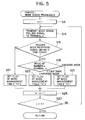
- the server 11 in the center 3 executes mode sense processes shown in the flowchart in Fig. 5 and the request processes shown in the flowchart in Fig. 6.
- the mode sense processes transmit the mode sense polling signals to all of the plurality of terminals 5 so as to detect the respective operation modes of all the terminals.
- the request processes transmit the request polling signals only to the terminals 5 that are determined by the mode sense processes to be in the karaoke mode so as to detect whether the terminals in the karaoke mode request transmission of karaoke songs.
- Request polling signals for interrogating whether or not a song request is present, are transmitted only to terminals 5 that are determined to be in karaoke mode by the mode sense processes.
- the mode sense processes of Fig. 5 are repeatedly executed every predetermined time period (for example, every 30 seconds) by a timer interrupt of the request processes. That is, the request processes are interrupted every predetermined time period, and the mode sense processes are executed.
- Mode sense polling signals are transmitted in succession to all of the karaoke terminals 5 connected to the center 3. Each terminal 5 transmits a mode response signal in response to these mode sense polling signals.
- the center 3 determines whether or not each terminal 5 is in the karaoke mode based on the mode response signals.
- the mode sense processes will now be described while referring to Fig. 5.
- the CPU 23 in the server 11 first sets the terminal number n to 1, in step S11. Then, the CPU 23 produces a mode sense polling signal added with the address code indicating the terminal number n, in step S13.
- the modem 15 modulates the mode sense polling signal and outputs it toward all the terminals 5.
- each of the karaoke terminals 5 refers to the address code attached to the mode sense polling signal to determine whether this mode sense polling signal is for itself. Accordingly, the number n terminal 5 determines that the mode sense polling signal added with the address code of the corresponding terminal number n is for itself.
- the program waits for reception of a mode response signal transmitted from the number n terminal 5 in response to the mode sense polling signal in step S15. It is noted that data indicating the present operation mode of the number n terminal is attached to the mode response signal.
- step S15 When a mode response signal is not transmitted within a predetermined period of time in step S15, the terminal is determined to be turned off. Accordingly, in step S17, the CPU 23 sets, to zero (0), a flag for the number n terminal in the mode management table in the RAM 27.
- step S17 the CPU 23 sets, to zero (0), a flag for the number n terminal in the mode management table in the RAM 27.
- the server 11 processes the mode response signal. That is, the server 11 refers to the data added to the mode response signal indicating the present operation mode of the number n terminal 5, and determines whether the operation mode of the number n terminal 5 is karaoke mode or not, in step S19.
- the CPU 23 sets the flag for the number n terminal of the mode management table to one (1) in step S21. If the number n karaoke terminal 5 is in the broadcast satellite or some other mode, then the flag is set to zero (0) in step S23.
- each terminal is in karaoke mode or not is determined according to the mode response signal transmitted from each terminal, and the results of the determinations are stored in the RAM 27. That is, when a mode response signal is received that indicates a terminal is in karaoke mode, the terminal is determined as being in karaoke mode and the mode flag is set to one (1). When a signal is not transmitted within a predetermined time, and when a mode response signal is received that indicates a mode other than the karaoke mode, that the mode is not karaoke mode is determined and the flag is set to zero (0).
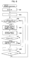
- the CPU 23 When the center 3 is turned ON, the CPU 23 starts conducting the request processes. The CPU 23 continues executing the request processes, until the center 3 is turned OFF.
- the CPU 23 first performs initialization to clear the RAM 27 and the like, in step S31. Then, in step S33, the CPU 23 sets the terminal number n to one (1).
- the CPU 23 refers the flag for the number n terminal 5 in the mode management table of the RAM 27 in step S35.
- the flag is determined as one (1), it is determined that the number n terminal is in the karaoke mode. Accordingly, the CPU 23 produces a request polling signal added with the address code indicating the terminal number n.
- the modem 15 modulates the request polling signal and outputs it toward all the terminals 5, in step S37.
- each of the karaoke terminals 5 refers to the address code attached to the request polling signal to determine whether this request polling signal is for itself. Accordingly, the number n terminal 5 determines that the request polling signal added with the address code of the corresponding terminal number n is for itself.
- a request response signal is transmitted from the number n terminal 5 to the center 3, in response to the request polling signal.
- the request response signal transmitted from the number n terminal indicates whether there is a request for a karaoke song at the number n terminal.
- the request response signal is added with the song number data and the like of the requested song. Accordingly, in step S41, the CPU 23 processes the request response signal to judge whether there is a song request at the number n terminal.
- step S43 the CPU 23 retrieves the karaoke song data for the requested song from the memory device 13, based on the song number data and the like included in the request response signal. The CPU 23 then transmits the karaoke song data to the number n terminal 5.
- the karaoke song data in the form as shown in Fig. 4 retrieved from the memory device 13 is added with an address code indicating the terminal number n, similarly to the mode sense polling signal and the request polling signal.
- the modem 15 modulates the karaoke song data and outputs it toward all the terminals 5.
- each of the karaoke terminals 5 refers to the address code attached thereto to determine whether this karaoke song data is for itself. Accordingly, the number n terminal 5 determines that the karaoke song data added with the address code of the corresponding terminal number n is transmitted for itself.
- step S45 If it is determined in the step S41 that there has been made no request in the number n terminal, the program proceeds directly to the step S45.
- the program proceeds directly to the step S45 without executing the above steps S37 through S43. That is, the request polling signals are not transmitted to the terminals not in the karaoke mode.
- request polling signals are transmitted only to terminals 5 that are in the karaoke mode.
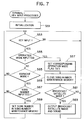
- Each terminal 5 executes key input processes indicated by the flowchart in Fig. 7 and transmission interrupt processes shown in Fig. 8.
- the key input processes of Fig. 7 are continually executed for detecting input from the keys of the input device 43 so as to receive the operation mode set to the terminal 5, input of the song number of a requested song, and the like.
- the key input processes are interrupted, and the transmission interruption processes of Fig 8 are executed.
- the transmission interruption processes performs processes for transmitting a mode response signals, that indicate the present operation mode of the terminal, to the center 3 in response to the mode sense polling signal and for transmitting a request response signal, that responds as to whether a song has been requested at the terminal, in response to the request polling signal.
- the transmission interruption processes also process the karaoke song data so that karaoke can be performed.
- the CPU 61 When the power source switch 43c is turned ON, the CPU 61 starts conducting the key input processes. The CPU 61 continues executing the key input processes, until the power source switch 43c is turned OFF.
- the CPU 61 in the control portion 41 first performs initialization to clear the RAM 65, in step S51. Then, the CPU 61 judges whether there has been some sort of key input from the input device 43 (that is, the key pad 43a, one of the mode keys 43b, and the like), in step S53. If no key input has been made, the program returns to step S53 and waits for key input.
- the CPU 61 judges whether the input is for setting the operation mode by manipulation of the mode key 43b, in step S55. If the input is input of the operation mode, in step S57, the CPU 61 sets, to one (1), a flag for the corresponding operation mode in the operation mode table of the RAM 65. For example, if the key input sets the operation mode of the terminal into the karaoke mode, the flag for karaoke mode in the table is set to one (1).
- step S59 the CPU 61 clears the song number maintenance memory in the RAM 65.
- step S61 the CPU further judges whether the present mode is the broadcast satellite mode, by referring to the flag of the operation mode table.
- the CPU 61 controls the video tuner 59 so as to select the broadcast satellite channel.
- the broadcast satellite image and the broadcast satellite sound are outputted to the monitor television 53 and the speaker 49 is step S63.
- the program again returns to the step S53.
- the CPU judges whether the present operation mode is the karaoke mode, in step S65, by referring to the operation mode table. If not, the program again returns to the step S53. If the present mode is the karaoke mode, the CPU judges whether the key input is a song number input of a requested song by the number pad 43a in step S67. If not, the program returns to the step S53. However, if the input is the song number input, the song number data is set in the above-described song number maintenance memory in the RAM 65, in step S69, whereupon the program returns to the step S53.
- the CPU 61 interrupts the key input processes of Fig. 7 and executes the transmission interruption processes.
- the CPU 61 first judges whether the polling signal inputted from the center 3 is a mode sense polling signal or not is determined in step S71. If determined as a mode sense polling signal, the CPU 61 produces a mode response signal, referring to the flag presently set in the operation mode table in the RAM 65. It is noted that the mode response signal has data added thereto that indicates the present operation mode of the terminal. The CPU then transmits the mode response signal via the modem 57 to the center 3, in step S73.
- the CPU judges whether there is a song request or not in step S75, by referring to the song number maintenance memory in the RAM 65. If no request is determined, the CPU 61 produces a request response signal indicating no request. Then, the CPU transmits the request response signal via the modem 57 to the center 3 in step S77. Then, the program returns to the key input processes of Fig. 7.
- the CPU If a request is determined in the step S75, the CPU produces a request response signal requesting transmission of karaoke song data of the requested song. Song number data and the like of the requested song are attached to this request response signal.
- the CPU transmits the request response signal via the modem 57 to the center 3 in step S79. Then, the terminal receives karaoke song data for the requested song transmitted from the center 3 in response to the request response signal.
- the CPU 61 temporarily stores the karaoke song data in the RAM 65 in step S81.
- karaoke performance processes are performed in step S83.
- the CPU 61 first refers to the song name/song genre information previously stored in the RAM 65, based on which the CPU controls the video tuner 59 to select a channel over which the background image signals corresponding to the genre of the requested song are being transmitted. Then, the CPU retrieves the karaoke song data for the requested song from the RAM 65. The CPU inputs the lyric data included in the karaoke song data to the image composition circuit 51 where the lyric data is converted into a lyric/image signal. Also, the background image signal transmitted over the channel selected by the video tuner 59 is inputted to the image composition circuit 51. The background image signal and the lyric/image signal are superimposed by the image composition circuit 51, whereupon the characters of the lyrics are displayed on the monitor television 53 superimposed on the background image.
- the CPU inputs the MIDI data (accompaniment data) included in the karaoke song data into the sound source 45, in which the MIDI data is converted into an accompaniment signal before being inputted to the amplifier 47.
- the accompaniment signal is mixed with the voice signal from the microphone 71 as sung by a user, amplified appropriately, and outputted to the speaker 49.
- step S83 When the above-described karaoke performance processes of step S83 are completed, the program returns to key input processes of Fig. 7.
- the center 3 transmits a mode sense polling signal, for confirming whether the operation mode of each karaoke terminal is karaoke mode, to each terminal 5 every time a predetermined duration of time passes.
- Each terminal 5 transmits to the center 3 a mode response signal indicating its present operation mode in response to this mode sense polling signal.
- the center 3 determines whether the operation mode of each terminal 5 is karaoke mode, based on this mode response signal. That is, when a mode response signal showing karaoke mode is received, that terminal is determined to be in karaoke mode.
- the terminal When no signal is transmitted within the predetermined time, or when a mode response signal indicating a mode other than the karaoke mode is received, the terminal is determined to not be in karaoke mode. According to the results of these determinations, request polling signals are transmitted only to terminals that are in the karaoke mode.
- request polling signals need not be transmitted to terminals that do not need karaoke song data (i.e, terminals 5 other than those in the karaoke mode).
- a great deal of wasteful polling time can be eliminated. Therefore, the waiting time until a request polling signal is received in a terminal 5 that is in the karaoke mode is reduced.
- Karaoke data of requested songs can be received in a short waiting time and users can immediately enjoy karaoke.
- the mode sense polling signal and the request polling signal are transmitted on the same channel. However, these can be divided and transmitted on separate channels so that both types of polling signals can be transmitted simultaneously. Because mode sense polling signals can be transmitted more frequently, the center 3 can rapidly determine change in the operation mode of each terminal 5.
- the karaoke song data is added with the address code indicating the terminal number n.
- the number n terminal 5 determines that the karaoke song data added with the address code of the corresponding terminal number n is transmitted for itself.
- other various methods for transmitting the karaoke song data to the desired terminal are available.
- control portion 41 in each terminal 5 may be controlled so as to determine that any karaoke song data is for itself, if the karaoke song data is transmitted thereto within a predetermined period of time after the control portion 41 transmits the request response signal to the center 3.
- the present invention is not limited to application to a karaoke system but can also be applied to systems for providing various types of information such as weather reports and traffic information.
- the central control unit transmits mode sense polling signals for confirming the operation modes of all the terminals.
- Each terminal transmits mode response signals indicating its present operation mode to the central control unit.
- a determination unit in the central control unit determines the operation mode of the terminals based on the mode response signals.
- a selection unit of the central control unit selects whether to transmit request polling signals to each terminal according to the determined operation mode.
- the central control unit can select not to transmit request polling signals, that interrogate about request for transmission of information data, to terminals set to operation modes where information data is not needed. Therefore, the number of terminals to which request polling signals are transmitted can be reduced and wasted polling time can be eliminated. Accordingly, the waiting time until a request polling signal is received at a terminal is reduced and desired information can be obtained in a short waiting time.
Landscapes
- Engineering & Computer Science (AREA)
- Signal Processing (AREA)
- Multimedia (AREA)
- Databases & Information Systems (AREA)
- Human Computer Interaction (AREA)
- Physics & Mathematics (AREA)
- Acoustics & Sound (AREA)
- Telephonic Communication Services (AREA)
- Computer And Data Communications (AREA)
- Two-Way Televisions, Distribution Of Moving Picture Or The Like (AREA)
- Reverberation, Karaoke And Other Acoustics (AREA)
- Selective Calling Equipment (AREA)
Applications Claiming Priority (2)
| Application Number | Priority Date | Filing Date | Title |
|---|---|---|---|
| JP5177015A JPH0738879A (ja) | 1993-07-16 | 1993-07-16 | データ伝送装置 |
| JP177015/93 | 1993-07-16 |
Publications (2)
| Publication Number | Publication Date |
|---|---|
| EP0634846A2 true EP0634846A2 (fr) | 1995-01-18 |
| EP0634846A3 EP0634846A3 (fr) | 1996-10-02 |
Family
ID=16023678
Family Applications (1)
| Application Number | Title | Priority Date | Filing Date |
|---|---|---|---|
| EP94305257A Withdrawn EP0634846A3 (fr) | 1993-07-16 | 1994-07-18 | Système de transmission de données pour la distribution de programmes audiovisuels dans un système de télédistribution. |
Country Status (5)
| Country | Link |
|---|---|
| US (1) | US5548281A (fr) |
| EP (1) | EP0634846A3 (fr) |
| JP (1) | JPH0738879A (fr) |
| CN (1) | CN1109242A (fr) |
| TW (1) | TW324128B (fr) |
Cited By (2)
| Publication number | Priority date | Publication date | Assignee | Title |
|---|---|---|---|---|
| EP0714684A1 (fr) * | 1994-11-29 | 1996-06-05 | Net Game Limited | Système de communication en temps réel de jeu multiutilisateur utilisant une infrastructure existante de télévision par câble |
| EP1019905A4 (fr) * | 1996-07-16 | 2004-05-12 | Gary S Tjaden | Systeme personnalise pour la distribution d'informations audio |
Families Citing this family (17)
| Publication number | Priority date | Publication date | Assignee | Title |
|---|---|---|---|---|
| US5781683A (en) * | 1993-05-14 | 1998-07-14 | Brother Kogyo Kabushiki Kaisha | Video reproducing apparatus with non-repetitive selecting function |
| JP3398423B2 (ja) * | 1993-07-16 | 2003-04-21 | ブラザー工業株式会社 | データ伝送装置、及び、端末装置 |
| JP3639319B2 (ja) * | 1994-01-25 | 2005-04-20 | 富士通株式会社 | 並列計算機システム,データ転送制御方法および送受信制御装置 |
| US5684843A (en) * | 1994-03-28 | 1997-11-04 | Brother Kogyo Kabushiki Kaisha | Data transmission system for transmitting information from a central control unit to a plurality of terminals |
| JPH07311583A (ja) * | 1994-05-17 | 1995-11-28 | Brother Ind Ltd | データ伝送装置 |
| JPH09127962A (ja) * | 1995-10-31 | 1997-05-16 | Pioneer Electron Corp | カラオケデータの送信方法および送受信装置 |
| JP3587916B2 (ja) * | 1995-10-31 | 2004-11-10 | ブラザー工業株式会社 | 映像音声データ供給装置 |
| US5887067A (en) * | 1996-05-10 | 1999-03-23 | General Signal Corporation | Audio communication system for a life safety network |
| US20090168624A1 (en) * | 1996-12-04 | 2009-07-02 | Marco Scibora | Apparatus and method for recording a custom compact disc at a retail premises |
| US6133908A (en) * | 1996-12-04 | 2000-10-17 | Advanced Communication Design, Inc. | Multi-station video/audio distribution apparatus |
| WO1998025364A2 (fr) | 1996-12-04 | 1998-06-11 | Advanced Communication Design, Inc. | Appareil multiposte de distribution audio |
| US7194555B2 (en) | 2000-01-12 | 2007-03-20 | Marco Scibora | Compression and remote storage apparatus for data, music and video |
| US20030167211A1 (en) * | 2002-03-04 | 2003-09-04 | Marco Scibora | Method and apparatus for digitally marking media content |
| JP4635738B2 (ja) * | 2005-06-24 | 2011-02-23 | ブラザー工業株式会社 | サービス提供システム、提供サーバおよびプログラム |
| CN1327658C (zh) * | 2005-08-09 | 2007-07-18 | 华为技术有限公司 | 网络通信状况探测方法 |
| JP2009260541A (ja) * | 2008-04-15 | 2009-11-05 | Sony Corp | 送信装置および方法、受信装置および方法、プログラム、並びに、送受信システムおよび方法 |
| CN115277482B (zh) * | 2022-06-10 | 2023-08-22 | 浙江清捷智能科技有限公司 | 一种工业边缘设备的在线检测方法 |
Family Cites Families (8)
| Publication number | Priority date | Publication date | Assignee | Title |
|---|---|---|---|---|
| JPS5628577A (en) * | 1979-08-16 | 1981-03-20 | Pioneer Electronic Corp | Data transmission method in catv system |
| US4595921A (en) * | 1983-08-11 | 1986-06-17 | Wang Laboratories, Inc. | Method of polling to ascertain service needs |
| EP0273080A1 (fr) * | 1986-12-30 | 1988-07-06 | International Business Machines Corporation | Procédé et dispositif pour interrogation à grande vitesse |
| US4896209A (en) * | 1987-02-10 | 1990-01-23 | Sony Corporation | Passenger vehicle polling system having a central unit for polling passenger seat terminal units |
| JPH063927B2 (ja) * | 1987-04-10 | 1994-01-12 | 富士通株式会社 | 最適化ブロツクポ−リング方式 |
| US4940974A (en) * | 1988-11-01 | 1990-07-10 | Norand Corporation | Multiterminal communication system and method |
| US5276810A (en) * | 1990-06-27 | 1994-01-04 | Victor Company Of Japan, Ltd. | Information item selection apparatus producing multi-channel output signals |
| US5194846A (en) * | 1991-05-07 | 1993-03-16 | General Signal Corporation | Communication system capable of broadcast messaging and transponder polling |
-
1993
- 1993-07-16 JP JP5177015A patent/JPH0738879A/ja active Pending
-
1994
- 1994-03-24 TW TW083102573A patent/TW324128B/zh active
- 1994-07-14 US US08/274,760 patent/US5548281A/en not_active Expired - Fee Related
- 1994-07-16 CN CN94108607A patent/CN1109242A/zh active Pending
- 1994-07-18 EP EP94305257A patent/EP0634846A3/fr not_active Withdrawn
Cited By (3)
| Publication number | Priority date | Publication date | Assignee | Title |
|---|---|---|---|---|
| EP0714684A1 (fr) * | 1994-11-29 | 1996-06-05 | Net Game Limited | Système de communication en temps réel de jeu multiutilisateur utilisant une infrastructure existante de télévision par câble |
| US5630757A (en) * | 1994-11-29 | 1997-05-20 | Net Game Limited | Real-time multi-user game communication system using existing cable television infrastructure |
| EP1019905A4 (fr) * | 1996-07-16 | 2004-05-12 | Gary S Tjaden | Systeme personnalise pour la distribution d'informations audio |
Also Published As
| Publication number | Publication date |
|---|---|
| US5548281A (en) | 1996-08-20 |
| CN1109242A (zh) | 1995-09-27 |
| TW324128B (en) | 1998-01-01 |
| JPH0738879A (ja) | 1995-02-07 |
| EP0634846A3 (fr) | 1996-10-02 |
Similar Documents
| Publication | Publication Date | Title |
|---|---|---|
| US5548281A (en) | Data transmission system | |
| US5774672A (en) | Data transmission system for distributing video and music data | |
| US5691915A (en) | Data transmission device | |
| US5613192A (en) | One-way data transmission device with two-way data transmission function | |
| US5619425A (en) | Data transmission system | |
| JP3250336B2 (ja) | カラオケシステムおよびカラオケ端末装置 | |
| US6083009A (en) | Karaoke service method and system by telecommunication system | |
| JPH0774854A (ja) | カラオケシステムおよびカラオケ装置 | |
| US5725383A (en) | Data transmission system | |
| US5684843A (en) | Data transmission system for transmitting information from a central control unit to a plurality of terminals | |
| US20140055672A1 (en) | Apparatus and method for processing additional information in television | |
| US5675509A (en) | Data transmission device | |
| JPH1152966A (ja) | 音楽演奏システム | |
| US20040127201A1 (en) | Cellular telephone having TV reproduction functions | |
| JPH11126085A (ja) | カラオケ装置 | |
| JP3345092B2 (ja) | カラオケ端末装置の集中管理システム | |
| JPH07273778A (ja) | データ伝送装置 | |
| JP3502494B2 (ja) | カラオケ装置 | |
| JPH09247628A (ja) | カラオケ装置 | |
| JP3893171B2 (ja) | 端末装置及び該端末装置を備えたデータ伝送システム | |
| JP2003195873A (ja) | ネットワークカラオケシステムの歌唱評価方法およびカラオケ装置 | |
| KR0148743B1 (ko) | 정보 텔레비젼의 노래방 선곡 방법 | |
| JPH07274156A (ja) | データ伝送装置 | |
| JPH07288801A (ja) | 通信型カラオケ演奏装置 | |
| JP2003233384A (ja) | ネットワーク自動演奏システムの楽音生成方法および自動演奏装置 |
Legal Events
| Date | Code | Title | Description |
|---|---|---|---|
| PUAI | Public reference made under article 153(3) epc to a published international application that has entered the european phase |
Free format text: ORIGINAL CODE: 0009012 |
|
| AK | Designated contracting states |
Kind code of ref document: A2 Designated state(s): DE GB |
|
| PUAL | Search report despatched |
Free format text: ORIGINAL CODE: 0009013 |
|
| AK | Designated contracting states |
Kind code of ref document: A3 Designated state(s): DE GB |
|
| 17P | Request for examination filed |
Effective date: 19970116 |
|
| STAA | Information on the status of an ep patent application or granted ep patent |
Free format text: STATUS: THE APPLICATION HAS BEEN WITHDRAWN |
|
| 18W | Application withdrawn |
Withdrawal date: 19990304 |