EP0634828A1 - Moteur électrique, en particulier moteur à commutateur ayant un paquet de tôles au stator - Google Patents
Moteur électrique, en particulier moteur à commutateur ayant un paquet de tôles au stator Download PDFInfo
- Publication number
- EP0634828A1 EP0634828A1 EP94110643A EP94110643A EP0634828A1 EP 0634828 A1 EP0634828 A1 EP 0634828A1 EP 94110643 A EP94110643 A EP 94110643A EP 94110643 A EP94110643 A EP 94110643A EP 0634828 A1 EP0634828 A1 EP 0634828A1
- Authority
- EP
- European Patent Office
- Prior art keywords
- electric motor
- motor according
- bearing plate
- connector housing
- housing
- Prior art date
- Legal status (The legal status is an assumption and is not a legal conclusion. Google has not performed a legal analysis and makes no representation as to the accuracy of the status listed.)
- Withdrawn
Links
Images


Classifications
-
- H—ELECTRICITY
- H02—GENERATION; CONVERSION OR DISTRIBUTION OF ELECTRIC POWER
- H02K—DYNAMO-ELECTRIC MACHINES
- H02K3/00—Details of windings
- H02K3/46—Fastening of windings on the stator or rotor structure
- H02K3/50—Fastening of winding heads, equalising connectors, or connections thereto
-
- H—ELECTRICITY
- H02—GENERATION; CONVERSION OR DISTRIBUTION OF ELECTRIC POWER
- H02K—DYNAMO-ELECTRIC MACHINES
- H02K5/00—Casings; Enclosures; Supports
- H02K5/04—Casings or enclosures characterised by the shape, form or construction thereof
- H02K5/14—Means for supporting or protecting brushes or brush holders
- H02K5/143—Means for supporting or protecting brushes or brush holders for cooperation with commutators
- H02K5/148—Slidably supported brushes
-
- H—ELECTRICITY
- H02—GENERATION; CONVERSION OR DISTRIBUTION OF ELECTRIC POWER
- H02K—DYNAMO-ELECTRIC MACHINES
- H02K5/00—Casings; Enclosures; Supports
- H02K5/04—Casings or enclosures characterised by the shape, form or construction thereof
- H02K5/15—Mounting arrangements for bearing-shields or end plates
-
- H—ELECTRICITY
- H02—GENERATION; CONVERSION OR DISTRIBUTION OF ELECTRIC POWER
- H02K—DYNAMO-ELECTRIC MACHINES
- H02K5/00—Casings; Enclosures; Supports
- H02K5/04—Casings or enclosures characterised by the shape, form or construction thereof
- H02K5/22—Auxiliary parts of casings not covered by groups H02K5/06-H02K5/20, e.g. shaped to form connection boxes or terminal boxes
- H02K5/225—Terminal boxes or connection arrangements
-
- H—ELECTRICITY
- H02—GENERATION; CONVERSION OR DISTRIBUTION OF ELECTRIC POWER
- H02K—DYNAMO-ELECTRIC MACHINES
- H02K7/00—Arrangements for handling mechanical energy structurally associated with dynamo-electric machines, e.g. structural association with mechanical driving motors or auxiliary dynamo-electric machines
- H02K7/20—Structural association with auxiliary dynamo-electric machines, e.g. with electric starter motors or exciters
-
- H—ELECTRICITY
- H02—GENERATION; CONVERSION OR DISTRIBUTION OF ELECTRIC POWER
- H02K—DYNAMO-ELECTRIC MACHINES
- H02K2203/00—Specific aspects not provided for in the other groups of this subclass relating to the windings
- H02K2203/06—Machines characterised by the wiring leads, i.e. conducting wires for connecting the winding terminations
Definitions
- the invention relates to an electric motor, in particular a commutator motor with a stator core, which is specified in the preamble of claim 1.
- the connecting device is assembled separately from several individual parts at the end of the assembly process and the connecting wires of the starter winding have to be connected to it.
- the ends of the wires forming the winding leading away from the stator windings are connected to stranded wires and then connected to a power source. The contact is made via crimp connections.
- the strands are attached to the coils with cable ties.
- a method for automatic pole pack production has also already been proposed, in which the ends of the winding wires are deposited by the stop housing in chambers provided for this purpose.
- the invention is based on the object of designing an electric motor, in particular a commutator motor with a stator core, in such a way that it can be assembled in as few work steps as possible in order to reduce the costs and time required for this.
- This object is achieved by the features characterized in claim 1.
- the pre-completion of the end shield including the strand guides and the tachometer generator can be done inexpensively.
- the motor is automatically switched by attaching the end shield and the automatically produced pole pack. This type of contacting can meet different customer needs in terms of different plugs and plug housings can be easily met.
- the connection of the end shield to the pole pack can also be carried out by an automatic machine.
- FIG. 1 shows a section through an electric motor, in particular through a commutator motor 1 with a stator core 3 and with an electrically insulating end plate 11 arranged on its end face 7.
- the housing has two cup-shaped end plates 19, 21 which are connected to one another by means of collar screws 17. These end shields 19, 21 each have a bearing point 23, 25 for ball bearings 27, 29, in which the rotor shaft 31 is rotatably mounted with a rotor laminated core 33.
- FIG. 5 shows a top view of an automatically produced pole package 35 with the end plate 11 with two connection housings 37, 39, which are arranged diametrically opposite one another on the outer edge of the free end face 41.
- connection housings 37, 39 are e.g. provided with four chambers 43, 44 with slots 45, 46 open on one side, via which the free ends 47, 49, 51, 53, 55, 57, 59, 61 of connecting wires 63, 65, 67, 69 can be deposited perpendicular to their length .
- terminals 71 are inserted in a known manner, through which the free ends 47, 49, 51, 53, 55, 57, 59, 61 of the connecting wires 63, 65, 67, 69 are securely fixed.
- These terminals 71 can consist of cutting contacts which penetrate the insulation of the winding ends and thereby penetrate contact with the tendons of the winding wires.
- a simple possibility for contacting between the customer-specific connector housing 73 on the motor housing and the pole package 35 produced by an automatic machine is created in that a bearing plate 19 consisting of a pre-completed assembly unit with the customer-specific connector housing 73, of carbon brushes 75, 77 and other components exists and with the connector housing 73 has electrically connected connectors 79, 81 which can be inserted for automatic contacting when the end shield 19 is placed on the pole package 35 in the connection housing 37, 39 on the end plate 11.
- the end shield 19 which can be done fully automatically, the commutator motor 1 is switched. This type of contacting can different customer requests with regard to different plugs and plug housings are taken into account.
- FIG. 2 shows a plan view of the pole pack 35 with the bearing plate 19 already attached
- the plugs 79, 81 are arranged integrated on a plate-shaped holding element 89, which consists of a plastic injection-molded part, which is connected to the end shield 19 by means of a snap-in connection.
- the pot-shaped bearing plate 19 has a base part 91 which is connected to the motor housing 18 via a connecting strut 95, 97, 99, 101 which forms the lateral surface 93 and a connecting flange 103 which is arranged concentrically with the base part 91.
- the holding element 89 consisting of a plastic injection molded part can be inserted into the bearing plate 19, projecting latching arms 105, 107 on the holding element 89 with latching lugs 106, 108 behind latching edges 110 of latching recesses 109 in the bottom part 91 of the bearing plate 19 being latchable.
- This knot connection provides simple mounting of the holding element 89 on the end shield 19.
- the holding element 89 has guide elements 119, 120, 121, 122, 123, 124 for the connecting leads 111, 112, 113, 114, 115, 116, 117 between the plug housing 73 and the plugs 79, 81 and to the other components.
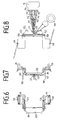
- the holding element 89 is provided on the connecting surface 125 between the plugs 79, 81 with two mutually resilient retaining webs 127, 129 for bundling all the stranded wires 111, 112, 113, 114, 115, 116, 117 to the plug housing 73, see FIGS. 7 and 8th.
- the bearing plate 19 furthermore has a passage opening 131 in the bottom part 91 for a pulse generator 135 arranged at the free end 133 of the rotor shaft 31, which is provided by a rotation detection element 137 of a tachometer generator 139 which is concentrically surrounding the latter is palpable.
- This rotation detection element 137 is surrounded by a cup-shaped cover cap 141, which is connected to the end shield 19 by means of a snap connection.
- the base part 91 contains locking recesses 143, 145, 147, 149 concentric with the passage opening 131, behind which locking hooks 151, 153, 155, 157 on the resilient locking arms 159, 161, 163, 165 of the cover cap 141 can be locked.
- the tachometer generator 139 is fixedly mounted on the end shield 19 before the end shield 19 is connected to the pole pack 35.
- a holding plate 167 is also connected to the end shield 19, on which the customer-specific connector housing 73 is fixed in position by means of latching means.
- the motor is switched through in the simplest way by simply placing the pre-assembled end shield 19 on the pole package 35.
Landscapes
- Engineering & Computer Science (AREA)
- Power Engineering (AREA)
- Motor Or Generator Frames (AREA)
Applications Claiming Priority (2)
| Application Number | Priority Date | Filing Date | Title |
|---|---|---|---|
| DE19934323065 DE4323065A1 (de) | 1993-07-10 | 1993-07-10 | Elektromotor, insbesondere Kommutatormotor mit einem Ständerblechpaket |
| DE4323065 | 1993-07-10 |
Publications (1)
| Publication Number | Publication Date |
|---|---|
| EP0634828A1 true EP0634828A1 (fr) | 1995-01-18 |
Family
ID=6492447
Family Applications (1)
| Application Number | Title | Priority Date | Filing Date |
|---|---|---|---|
| EP94110643A Withdrawn EP0634828A1 (fr) | 1993-07-10 | 1994-07-08 | Moteur électrique, en particulier moteur à commutateur ayant un paquet de tôles au stator |
Country Status (4)
| Country | Link |
|---|---|
| EP (1) | EP0634828A1 (fr) |
| CZ (1) | CZ165494A3 (fr) |
| DE (1) | DE4323065A1 (fr) |
| SI (1) | SI9400283A (fr) |
Cited By (3)
| Publication number | Priority date | Publication date | Assignee | Title |
|---|---|---|---|---|
| ES2157783A1 (es) * | 1999-05-06 | 2001-08-16 | Soler & Palau | Rejilla protectora para motores electricos. |
| WO2006123304A2 (fr) * | 2005-05-18 | 2006-11-23 | Arcelik Anonim Sirketi | Moteur |
| FR2931597A1 (fr) * | 2008-05-26 | 2009-11-27 | Valeo Systemes Thermiques | Bague de reception d'un moteur electrique a sortie filaire pour un groupe moto-ventilateur d'une installation de chauffage, de ventilation et/ou de climatisation d'un vehicule automobile |
Citations (3)
| Publication number | Priority date | Publication date | Assignee | Title |
|---|---|---|---|---|
| DE1538724B2 (de) * | 1966-11-26 | 1971-04-29 | Ackermann u Schmitt KG, 7000 Stutt gart | Elektrische maschine |
| US4845396A (en) * | 1986-08-19 | 1989-07-04 | Capsonic Group, Inc. | Motor brush holder assembly |
| DE3805060A1 (de) * | 1988-02-18 | 1989-08-31 | Miele & Cie | Elektromotor mit einem systemtraeger zur aufnahme von bauelementen, leiterbahnen und steuer- bzw. regelbausteinen |
Family Cites Families (4)
| Publication number | Priority date | Publication date | Assignee | Title |
|---|---|---|---|---|
| US3984908A (en) * | 1975-10-01 | 1976-10-12 | Amp Incorporated | Stator terminal assembly machine |
| DE3513155A1 (de) * | 1985-04-12 | 1986-10-23 | Licentia Gmbh | Antriebsmotor fuer ein geraet |
| DE3604675A1 (de) * | 1985-04-12 | 1987-08-20 | Licentia Gmbh | Antriebsmotor fuer ein geraet |
| IT214920Z2 (it) * | 1988-11-04 | 1990-07-04 | Magneti Marelli Spa | Portaspazzole per una macchina elettrica in corrente continua in particolare per il motore di un elettro ventilatore per il raffreddamento del radiatore di un motore a combustione interna |
-
1993
- 1993-07-10 DE DE19934323065 patent/DE4323065A1/de not_active Withdrawn
-
1994
- 1994-07-08 CZ CZ941654A patent/CZ165494A3/cs unknown
- 1994-07-08 EP EP94110643A patent/EP0634828A1/fr not_active Withdrawn
- 1994-07-11 SI SI9400283A patent/SI9400283A/sl unknown
Patent Citations (3)
| Publication number | Priority date | Publication date | Assignee | Title |
|---|---|---|---|---|
| DE1538724B2 (de) * | 1966-11-26 | 1971-04-29 | Ackermann u Schmitt KG, 7000 Stutt gart | Elektrische maschine |
| US4845396A (en) * | 1986-08-19 | 1989-07-04 | Capsonic Group, Inc. | Motor brush holder assembly |
| DE3805060A1 (de) * | 1988-02-18 | 1989-08-31 | Miele & Cie | Elektromotor mit einem systemtraeger zur aufnahme von bauelementen, leiterbahnen und steuer- bzw. regelbausteinen |
Cited By (5)
| Publication number | Priority date | Publication date | Assignee | Title |
|---|---|---|---|---|
| ES2157783A1 (es) * | 1999-05-06 | 2001-08-16 | Soler & Palau | Rejilla protectora para motores electricos. |
| WO2006123304A2 (fr) * | 2005-05-18 | 2006-11-23 | Arcelik Anonim Sirketi | Moteur |
| WO2006123304A3 (fr) * | 2005-05-18 | 2007-02-08 | Arcelik As | Moteur |
| CN101189781B (zh) * | 2005-05-18 | 2011-10-12 | 阿塞里克股份有限公司 | 发动机 |
| FR2931597A1 (fr) * | 2008-05-26 | 2009-11-27 | Valeo Systemes Thermiques | Bague de reception d'un moteur electrique a sortie filaire pour un groupe moto-ventilateur d'une installation de chauffage, de ventilation et/ou de climatisation d'un vehicule automobile |
Also Published As
| Publication number | Publication date |
|---|---|
| CZ165494A3 (en) | 1995-01-18 |
| SI9400283A (en) | 1995-04-30 |
| DE4323065A1 (de) | 1995-01-19 |
Similar Documents
| Publication | Publication Date | Title |
|---|---|---|
| DE3912873C2 (fr) | ||
| DE3629634C2 (fr) | ||
| EP1384307A1 (fr) | Moteur a courant continu a commutation electronique | |
| DE3300494A1 (de) | Drehstromgenerator fuer fahrzeuge, insbesondere mit einem klauenpol-laeufer | |
| EP1689065A1 (fr) | Stator pour machine électrique | |
| DE102009038258A1 (de) | Bürstenträger eines Motors | |
| WO2015082220A2 (fr) | Stator pour moteur à courant continu à commutation électronique | |
| EP0797859A1 (fr) | Plaque porte-balai | |
| DE19618958A1 (de) | Modulare Bürsteneinsteckkassette | |
| DE10130117A1 (de) | Gehäusedeckel für einen Elektromotor, insbesondere für einen elektronisch kommutierten Gleichstrommotor | |
| DE3538940A1 (de) | Verdrahtungsanordnung fuer den motor eines elektrowerkzeugs | |
| DE3447826A1 (de) | Aussenlaeufermotor mit anschlusssteckverbindung | |
| DE202006007808U1 (de) | Statorendscheibe für einen Kommutatormotor und Kommutatormotor | |
| EP0504469B1 (fr) | Connexion à contact électrique | |
| DE102009038144A1 (de) | Elektromotor | |
| DE20212273U1 (de) | Stator für einen Elektromotor | |
| EP1024581A2 (fr) | Connexions des enroulements d'un moteur | |
| EP0175992B1 (fr) | Procédé pour la fabrication d'un support pour les balais d'une machine à collecteur | |
| EP0634828A1 (fr) | Moteur électrique, en particulier moteur à commutateur ayant un paquet de tôles au stator | |
| DE19756575B4 (de) | Elektromotor | |
| DE3012634A1 (de) | Buerstenhalter fuer generatoren von kraftfahrzeugen | |
| DE19606141A1 (de) | Kabelführungsträger für einen Universalmotor | |
| DE102008053567A1 (de) | Elektrischer Antrieb | |
| WO2020156829A1 (fr) | Pompe présentant une liaison directe du stator à la carte de circuits imprimés | |
| EP1171942B1 (fr) | Procede de realisation d'un flasque pour moteur a commutateur et flasque fabrique suivant cette methode |
Legal Events
| Date | Code | Title | Description |
|---|---|---|---|
| PUAI | Public reference made under article 153(3) epc to a published international application that has entered the european phase |
Free format text: ORIGINAL CODE: 0009012 |
|
| AK | Designated contracting states |
Kind code of ref document: A1 Designated state(s): DE ES FR GB IT |
|
| 17P | Request for examination filed |
Effective date: 19950222 |
|
| 17Q | First examination report despatched |
Effective date: 19950511 |
|
| GRAH | Despatch of communication of intention to grant a patent |
Free format text: ORIGINAL CODE: EPIDOS IGRA |
|
| STAA | Information on the status of an ep patent application or granted ep patent |
Free format text: STATUS: THE APPLICATION IS DEEMED TO BE WITHDRAWN |
|
| GRAH | Despatch of communication of intention to grant a patent |
Free format text: ORIGINAL CODE: EPIDOS IGRA |
|
| 18D | Application deemed to be withdrawn |
Effective date: 19960702 |