EP0634828A1 - Electrical motor, in particular commutator motor with a stator stack of sheet - Google Patents
Electrical motor, in particular commutator motor with a stator stack of sheet Download PDFInfo
- Publication number
- EP0634828A1 EP0634828A1 EP94110643A EP94110643A EP0634828A1 EP 0634828 A1 EP0634828 A1 EP 0634828A1 EP 94110643 A EP94110643 A EP 94110643A EP 94110643 A EP94110643 A EP 94110643A EP 0634828 A1 EP0634828 A1 EP 0634828A1
- Authority
- EP
- European Patent Office
- Prior art keywords
- electric motor
- motor according
- bearing plate
- connector housing
- housing
- Prior art date
- Legal status (The legal status is an assumption and is not a legal conclusion. Google has not performed a legal analysis and makes no representation as to the accuracy of the status listed.)
- Withdrawn
Links
Images


Classifications
-
- H—ELECTRICITY
- H02—GENERATION; CONVERSION OR DISTRIBUTION OF ELECTRIC POWER
- H02K—DYNAMO-ELECTRIC MACHINES
- H02K3/00—Details of windings
- H02K3/46—Fastening of windings on the stator or rotor structure
- H02K3/50—Fastening of winding heads, equalising connectors, or connections thereto
-
- H—ELECTRICITY
- H02—GENERATION; CONVERSION OR DISTRIBUTION OF ELECTRIC POWER
- H02K—DYNAMO-ELECTRIC MACHINES
- H02K5/00—Casings; Enclosures; Supports
- H02K5/04—Casings or enclosures characterised by the shape, form or construction thereof
- H02K5/14—Means for supporting or protecting brushes or brush holders
- H02K5/143—Means for supporting or protecting brushes or brush holders for cooperation with commutators
- H02K5/148—Slidably supported brushes
-
- H—ELECTRICITY
- H02—GENERATION; CONVERSION OR DISTRIBUTION OF ELECTRIC POWER
- H02K—DYNAMO-ELECTRIC MACHINES
- H02K5/00—Casings; Enclosures; Supports
- H02K5/04—Casings or enclosures characterised by the shape, form or construction thereof
- H02K5/15—Mounting arrangements for bearing-shields or end plates
-
- H—ELECTRICITY
- H02—GENERATION; CONVERSION OR DISTRIBUTION OF ELECTRIC POWER
- H02K—DYNAMO-ELECTRIC MACHINES
- H02K5/00—Casings; Enclosures; Supports
- H02K5/04—Casings or enclosures characterised by the shape, form or construction thereof
- H02K5/22—Auxiliary parts of casings not covered by groups H02K5/06-H02K5/20, e.g. shaped to form connection boxes or terminal boxes
- H02K5/225—Terminal boxes or connection arrangements
-
- H—ELECTRICITY
- H02—GENERATION; CONVERSION OR DISTRIBUTION OF ELECTRIC POWER
- H02K—DYNAMO-ELECTRIC MACHINES
- H02K7/00—Arrangements for handling mechanical energy structurally associated with dynamo-electric machines, e.g. structural association with mechanical driving motors or auxiliary dynamo-electric machines
- H02K7/20—Structural association with auxiliary dynamo-electric machines, e.g. with electric starter motors or exciters
-
- H—ELECTRICITY
- H02—GENERATION; CONVERSION OR DISTRIBUTION OF ELECTRIC POWER
- H02K—DYNAMO-ELECTRIC MACHINES
- H02K2203/00—Specific aspects not provided for in the other groups of this subclass relating to the windings
- H02K2203/06—Machines characterised by the wiring leads, i.e. conducting wires for connecting the winding terminations
Definitions
- the invention relates to an electric motor, in particular a commutator motor with a stator core, which is specified in the preamble of claim 1.
- the connecting device is assembled separately from several individual parts at the end of the assembly process and the connecting wires of the starter winding have to be connected to it.
- the ends of the wires forming the winding leading away from the stator windings are connected to stranded wires and then connected to a power source. The contact is made via crimp connections.
- the strands are attached to the coils with cable ties.
- a method for automatic pole pack production has also already been proposed, in which the ends of the winding wires are deposited by the stop housing in chambers provided for this purpose.
- the invention is based on the object of designing an electric motor, in particular a commutator motor with a stator core, in such a way that it can be assembled in as few work steps as possible in order to reduce the costs and time required for this.
- This object is achieved by the features characterized in claim 1.
- the pre-completion of the end shield including the strand guides and the tachometer generator can be done inexpensively.
- the motor is automatically switched by attaching the end shield and the automatically produced pole pack. This type of contacting can meet different customer needs in terms of different plugs and plug housings can be easily met.
- the connection of the end shield to the pole pack can also be carried out by an automatic machine.
- FIG. 1 shows a section through an electric motor, in particular through a commutator motor 1 with a stator core 3 and with an electrically insulating end plate 11 arranged on its end face 7.
- the housing has two cup-shaped end plates 19, 21 which are connected to one another by means of collar screws 17. These end shields 19, 21 each have a bearing point 23, 25 for ball bearings 27, 29, in which the rotor shaft 31 is rotatably mounted with a rotor laminated core 33.
- FIG. 5 shows a top view of an automatically produced pole package 35 with the end plate 11 with two connection housings 37, 39, which are arranged diametrically opposite one another on the outer edge of the free end face 41.
- connection housings 37, 39 are e.g. provided with four chambers 43, 44 with slots 45, 46 open on one side, via which the free ends 47, 49, 51, 53, 55, 57, 59, 61 of connecting wires 63, 65, 67, 69 can be deposited perpendicular to their length .
- terminals 71 are inserted in a known manner, through which the free ends 47, 49, 51, 53, 55, 57, 59, 61 of the connecting wires 63, 65, 67, 69 are securely fixed.
- These terminals 71 can consist of cutting contacts which penetrate the insulation of the winding ends and thereby penetrate contact with the tendons of the winding wires.
- a simple possibility for contacting between the customer-specific connector housing 73 on the motor housing and the pole package 35 produced by an automatic machine is created in that a bearing plate 19 consisting of a pre-completed assembly unit with the customer-specific connector housing 73, of carbon brushes 75, 77 and other components exists and with the connector housing 73 has electrically connected connectors 79, 81 which can be inserted for automatic contacting when the end shield 19 is placed on the pole package 35 in the connection housing 37, 39 on the end plate 11.
- the end shield 19 which can be done fully automatically, the commutator motor 1 is switched. This type of contacting can different customer requests with regard to different plugs and plug housings are taken into account.
- FIG. 2 shows a plan view of the pole pack 35 with the bearing plate 19 already attached
- the plugs 79, 81 are arranged integrated on a plate-shaped holding element 89, which consists of a plastic injection-molded part, which is connected to the end shield 19 by means of a snap-in connection.
- the pot-shaped bearing plate 19 has a base part 91 which is connected to the motor housing 18 via a connecting strut 95, 97, 99, 101 which forms the lateral surface 93 and a connecting flange 103 which is arranged concentrically with the base part 91.
- the holding element 89 consisting of a plastic injection molded part can be inserted into the bearing plate 19, projecting latching arms 105, 107 on the holding element 89 with latching lugs 106, 108 behind latching edges 110 of latching recesses 109 in the bottom part 91 of the bearing plate 19 being latchable.
- This knot connection provides simple mounting of the holding element 89 on the end shield 19.
- the holding element 89 has guide elements 119, 120, 121, 122, 123, 124 for the connecting leads 111, 112, 113, 114, 115, 116, 117 between the plug housing 73 and the plugs 79, 81 and to the other components.
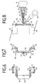
- the holding element 89 is provided on the connecting surface 125 between the plugs 79, 81 with two mutually resilient retaining webs 127, 129 for bundling all the stranded wires 111, 112, 113, 114, 115, 116, 117 to the plug housing 73, see FIGS. 7 and 8th.
- the bearing plate 19 furthermore has a passage opening 131 in the bottom part 91 for a pulse generator 135 arranged at the free end 133 of the rotor shaft 31, which is provided by a rotation detection element 137 of a tachometer generator 139 which is concentrically surrounding the latter is palpable.
- This rotation detection element 137 is surrounded by a cup-shaped cover cap 141, which is connected to the end shield 19 by means of a snap connection.
- the base part 91 contains locking recesses 143, 145, 147, 149 concentric with the passage opening 131, behind which locking hooks 151, 153, 155, 157 on the resilient locking arms 159, 161, 163, 165 of the cover cap 141 can be locked.
- the tachometer generator 139 is fixedly mounted on the end shield 19 before the end shield 19 is connected to the pole pack 35.
- a holding plate 167 is also connected to the end shield 19, on which the customer-specific connector housing 73 is fixed in position by means of latching means.
- the motor is switched through in the simplest way by simply placing the pre-assembled end shield 19 on the pole package 35.
Abstract
Description
Die Erfindung betrifft einen Elektromotor, insbesondere einen Kommutatormotor mit einem Ständerblechpaket, der im Oberbegriff des Patentanspruchs 1 angegebenen Art.The invention relates to an electric motor, in particular a commutator motor with a stator core, which is specified in the preamble of
Bei bekannten Motorbauarten hat es sich für die Fertigung als nachteilig herausgestellt, wenn die Anschlußvorrichtung am Ende des Montagevorganges aus mehreren Einzelteilen getrennt zusammengefügt und die Anschlußdrähte der Starterwicklung damit verbunden werden müssen. Hierbei werden die von den Ständerwicklungen wegführenden Enden der die Wicklung bildenden Drähte mit Litzendrähten verbunden und dann an eine Stromquelle angeschlossen. Die Kontaktierung erfolgt hierbei über Krimpverbindungen. Außerdem werden die Litzen mittels Kabelbinder an den Spulen befestigt.In known motor types, it has been found to be disadvantageous for production if the connecting device is assembled separately from several individual parts at the end of the assembly process and the connecting wires of the starter winding have to be connected to it. Here, the ends of the wires forming the winding leading away from the stator windings are connected to stranded wires and then connected to a power source. The contact is made via crimp connections. In addition, the strands are attached to the coils with cable ties.
Auch ist bereits ein Verfahren für eine automatische Polpaketfertigung vorgeschlagen worden, bei der die Enden der Wicklungsdrähte in dafür vorgesehene Kammern vom Anschlaggehäuse abgelegt werden.A method for automatic pole pack production has also already been proposed, in which the ends of the winding wires are deposited by the stop housing in chambers provided for this purpose.
Der Erfindung liegt nun die Aufgabe zugrunde, einen Elektromotor, insbesondere einen Kommutatormotor mit einem Ständerblechpaket so zu gestalten, daß seine Montage in möglichst wenig Arbeitsgängen einfach erfolgen kann, um den dafür erforderlichen Kosten- und Zeitaufwand zu reduzieren. Diese Aufgabe wird durch die im Patentanspruch 1 gekennzeichneten Merkmale gelöst.The invention is based on the object of designing an electric motor, in particular a commutator motor with a stator core, in such a way that it can be assembled in as few work steps as possible in order to reduce the costs and time required for this. This object is achieved by the features characterized in
Die Vorkomplettierung des Lagerschildes einschließlich der Litzenführungen und des Tachogenerators kann kostengünstig erfolgen. Durch das Aufsetzen des Lagerschildes und das automatisch hergestellte Polpaket wird der Motor automatisch geschaltet. Durch diese Art der Kontaktierung kann den verschiedenen Kundenwünschen in Bezug auf unterschiedliche Stecker und Steckergehäuse auf einfachste Weise entsprochen werden. Die Verbindung des Lagerschildes mit dem Polpaket kann auch durch einen Automaten vorgenommen werden.The pre-completion of the end shield including the strand guides and the tachometer generator can be done inexpensively. The motor is automatically switched by attaching the end shield and the automatically produced pole pack. This type of contacting can meet different customer needs in terms of different plugs and plug housings can be easily met. The connection of the end shield to the pole pack can also be carried out by an automatic machine.
Weitere Einzelheiten des Erfindungsgegenstandes sind den weiteren Unteransprüchen zu entnehmen.Further details of the subject matter of the invention can be found in the further subclaims.
Die Erfindung wird anhand eines Ausführungsbeispiels im folgenden näher beschrieben. Es zeigen:
Figur 1- einen Schnitt durch den erfindungsgemäßen Elektromotor,
- Figur 2
- eine Draufsicht auf ein Lagerschild des Elektromotors,
Figur 3- eine Seitenansicht auf einen Teil des Elektromotors, teilweise im Schnitt,
- Figur 4
- eine Draufsicht auf das Halteelement,
Figur 5- eine Draufsicht auf eine Endscheibe eines Polpaketes und
- Figuren 6-8
- verschiedene Ansichten des Halteelementes.
- Figure 1
- 2 shows a section through the electric motor according to the invention,
- Figure 2
- a plan view of a bearing plate of the electric motor,
- Figure 3
- a side view of part of the electric motor, partially in section,
- Figure 4
- a plan view of the holding element,
- Figure 5
- a plan view of an end plate of a pole pack and
- Figures 6-8
- different views of the holding element.
Die Figur 1 zeigt einen Schnitt durch einen Elektromotor, insbesondere durch einen Kommutatormotor 1 mit einem Ständerblechpaket 3 und mit an dessen stirnseitiger Endfläche 7 angeordneten, elektrisch isolierenden Endscheibe 11. Das Gehäuse weist zwei topfförmig ausgebildete Lagerschilde 19, 21 auf, die mittels Bundschrauben 17 miteinander verbunden sind. Diese Lagerschilde 19, 21 weisen je eine Lagerstelle 23, 25 für Kugellager 27, 29 auf, in welchen die Rotorwelle 31 mit einem Rotorblechpaket 33 drehbar gelagert ist.FIG. 1 shows a section through an electric motor, in particular through a
Die Figur 5 zeigt eine Draufsicht auf ein automatisch hergestelltes Polpaket 35 mit der Endscheibe 11 mit zwei Anschlußgehäusen 37, 39, welche diametral gegenüberliegend an dem äußeren Rand der freien Stirnfläche 41 angeordnet sind. Diese Anschlußgehäuse 37, 39 sind z.B. mit vier Kammern 43, 44 mit einseitig offenen Schlitzen 45, 46 versehen, über welche die freien Enden 47, 49, 51, 53, 55, 57, 59, 61 von Anschlußdrähten 63, 65, 67, 69 senkrecht zu ihrer Länge ablegbar sind. In diese Kammern 43, 44 sind in bekannter Weise Klemmen 71 eingesetzt, durch die die freien Enden 47, 49, 51, 53, 55, 57, 59, 61 der Anschlußdrähte 63, 65, 67, 69 sicher fixiert sind. Diese Klemmen 71 können aus Schneidkontakten bestehen, die die Isolierung der Wicklungsenden durchdringen und dadurch einen Kontakt zu den Sehnen der Wicklungsdrähte durchdringen.FIG. 5 shows a top view of an automatically produced
Erfindungsgemäß wird nun eine einfache Möglichkeit für eine Kontaktierung zwischen dem kundenspezifischen Steckergehäuse 73 an dem Motorgehäuse und dem durch einen Automaten hergestellten Polpaket 35 dadurch geschaffen, daß ein Lagerschild 19 aus einer vorkomplettierten Montageeinheit mit dem kundenspezifischen Steckergehäuse 73, von Kohlebürsten 75, 77 und sonstigen Bauelementen besteht und mit dem Steckergehäuse 73 elektrisch verbundene Stecker 79, 81 aufweist, welche beim Aufsetzen des Lagerschildes 19 auf das Polpaket 35 in die Anschlußgehäuse 37, 39 an der Endscheibe 11 zur automatischen Kontaktierung einführbar sind. Durch das Aufsetzen des Lagerschildes 19, was voll automatisch erfolgen kann, wird der Kommutatormotor 1 geschaltet. Durch diese Art der Kontaktierung kann den verschiedenen Kundenwünschen in Bezug auf unterschiedliche Stecker und Steckergehäuse Rechnung getragen werden.According to the invention, a simple possibility for contacting between the customer-
Die in dem Lagerschild 19 in Bürstenführungen 85, 87 abgefedert gelagerten Kohlebürsten 75, 77 wirken in bekannter Weise mit einem Kollektor 83 auf der Rotorwelle 31 zusammen, siehe Figur 1. Die Figur 2 zeigt eine Draufsicht auf das Polpaket 35 mit dem bereits aufgesetzten Lagerschild 19. Die Stecker 79, 81 sind an einem plattenförmig ausgebildeten Halteelement 89, das aus einem Kunststoffspritzteil besteht, integriert angeordnet, welches mittels einer Rastverbindung mit dem Lagerschild 19 verbunden ist. Das topfförmige Lagerschild 19 weist ein Bodenteil 91 auf, das über die Mantelfläche 93 bildende Verbindungsstreben 95, 97, 99, 101 mit einem konzentrisch zu dem Bodenteil 91 angeordneten Verbindungsflansch 103 zu dem Motorgehäuse 18 verbunden ist. Das aus einem Kunststoffspritzteil bestehende Halteelement 89 ist in das Lagerschild 19 einlegbar, wobei vorstehende Rastarme 105, 107 an dem Halteelement 89 mit Rastnasen 106, 108 hinter Rastkanten 110 von Rastausnehmungen 109 in dem Bodenteil 91 des Lagerschildes 19 verrastbar sind. Durch diese Knüpfverbindung ist eine einfache Montage des Halteelementes 89 an dem Lagerschild 19 gegeben. Das Halteelement 89 weist Führungselemente 119, 120, 121, 122, 123, 124 für die Anschlußlitze 111, 112, 113, 114, 115, 116, 117 zwischen dem Steckergehäuse 73 und den Steckern 79, 81 und zu den sonstigen Bauelementen auf. Außerdem ist das Halteelement 89 auf der Verbindungsfläche 125 zwischen den Steckern 79, 81 mit zwei gegeneinander federnden Haltestege 127, 129 zur Bündelung aller Anschlußlitzen 111, 112, 113, 114, 115, 116, 117 zu dem Steckergehäuse 73 versehen, siehe Figuren 7 und 8.The
Das Lagerschild 19 weist weiterhin im Bodenteil 91 eine Durchtrittsöffnung 131 für einen an dem freien Ende 133 der Rotorwelle 31 angeordneten Impulsgeber 135 auf, welcher von einem diesem konzentrisch umgebenen Dreherkennungselement 137 eines Tachogenerators 139 abtastbar ist. Dieses Dreherkennungselement 137 ist von einer topfförmigen Abdeckkappe 141 umgeben, welche mittels einer Rastverbindung mit dem Lagerschild 19 verbunden ist. Zu diesem Zweck enthält das Bodenteil 91 konzentrisch zu der Durchtrittsöffnung 131 Rastausnehmungen 143, 145, 147, 149, hinter welche Rasthaken 151, 153, 155, 157 an den federnden Rastarmen 159, 161, 163, 165 der Abdeckkappe 141 verrastbar sind. Der Tachogenerator 139 wird übrigens vor der Verbindung des Lagerschildes 19 mit dem Polpaket 35 auf dem Lagerschild 19 fest montiert. Auch ist mit dem Lagerschild 19 ein Halteblech 167 verbunden, auf welchem das kundenspezifische Steckergehäuse 73 mittels Rastmittel fixiert gelagert ist.The
Durch das einfache Aufsetzen des vorkomplettierten Lagerschildes 19 auf das Polpaket 35 wird der Motor auf einfachste Weise durchgeschaltet.The motor is switched through in the simplest way by simply placing the
Claims (10)
Applications Claiming Priority (2)
| Application Number | Priority Date | Filing Date | Title |
|---|---|---|---|
| DE4323065 | 1993-07-10 | ||
| DE19934323065 DE4323065A1 (en) | 1993-07-10 | 1993-07-10 | Electric motor, especially commutator motor with a stator core |
Publications (1)
| Publication Number | Publication Date |
|---|---|
| EP0634828A1 true EP0634828A1 (en) | 1995-01-18 |
Family
ID=6492447
Family Applications (1)
| Application Number | Title | Priority Date | Filing Date |
|---|---|---|---|
| EP94110643A Withdrawn EP0634828A1 (en) | 1993-07-10 | 1994-07-08 | Electrical motor, in particular commutator motor with a stator stack of sheet |
Country Status (4)
| Country | Link |
|---|---|
| EP (1) | EP0634828A1 (en) |
| CZ (1) | CZ165494A3 (en) |
| DE (1) | DE4323065A1 (en) |
| SI (1) | SI9400283A (en) |
Cited By (3)
| Publication number | Priority date | Publication date | Assignee | Title |
|---|---|---|---|---|
| ES2157783A1 (en) * | 1999-05-06 | 2001-08-16 | Soler & Palau | Protection mesh for electrical engines |
| WO2006123304A2 (en) * | 2005-05-18 | 2006-11-23 | Arcelik Anonim Sirketi | A motor |
| FR2931597A1 (en) * | 2008-05-26 | 2009-11-27 | Valeo Systemes Thermiques | Electric engine receiving ring for motor driven fan of heating, ventilation and/or air conditioning installation of motor vehicle, has receptacle arranged at interior of peripheral volume of ring, where volume is adjacent to external face |
Citations (3)
| Publication number | Priority date | Publication date | Assignee | Title |
|---|---|---|---|---|
| DE1538724B2 (en) * | 1966-11-26 | 1971-04-29 | Ackermann u Schmitt KG, 7000 Stutt gart | ELECTRIC MACHINE |
| US4845396A (en) * | 1986-08-19 | 1989-07-04 | Capsonic Group, Inc. | Motor brush holder assembly |
| DE3805060A1 (en) * | 1988-02-18 | 1989-08-31 | Miele & Cie | Electric motor having a system carrier for accommodating components, conductor tracks and control and regulation modules (chips) |
Family Cites Families (4)
| Publication number | Priority date | Publication date | Assignee | Title |
|---|---|---|---|---|
| US3984908A (en) * | 1975-10-01 | 1976-10-12 | Amp Incorporated | Stator terminal assembly machine |
| DE3604675A1 (en) * | 1985-04-12 | 1987-08-20 | Licentia Gmbh | Drive motor for an apparatus (appliance) |
| DE3513155A1 (en) * | 1985-04-12 | 1986-10-23 | Licentia Gmbh | Drive motor for an apparatus |
| IT214920Z2 (en) * | 1988-11-04 | 1990-07-04 | Magneti Marelli Spa | BRUSH HOLDER FOR A DIRECT CURRENT ELECTRIC MACHINE IN PARTICULAR FOR THE MOTOR OF AN ELECTRIC FAN FOR COOLING THE RADIATOR OF AN INTERNAL COMBUSTION ENGINE |
-
1993
- 1993-07-10 DE DE19934323065 patent/DE4323065A1/en not_active Withdrawn
-
1994
- 1994-07-08 CZ CZ941654A patent/CZ165494A3/en unknown
- 1994-07-08 EP EP94110643A patent/EP0634828A1/en not_active Withdrawn
- 1994-07-11 SI SI9400283A patent/SI9400283A/en unknown
Patent Citations (3)
| Publication number | Priority date | Publication date | Assignee | Title |
|---|---|---|---|---|
| DE1538724B2 (en) * | 1966-11-26 | 1971-04-29 | Ackermann u Schmitt KG, 7000 Stutt gart | ELECTRIC MACHINE |
| US4845396A (en) * | 1986-08-19 | 1989-07-04 | Capsonic Group, Inc. | Motor brush holder assembly |
| DE3805060A1 (en) * | 1988-02-18 | 1989-08-31 | Miele & Cie | Electric motor having a system carrier for accommodating components, conductor tracks and control and regulation modules (chips) |
Cited By (5)
| Publication number | Priority date | Publication date | Assignee | Title |
|---|---|---|---|---|
| ES2157783A1 (en) * | 1999-05-06 | 2001-08-16 | Soler & Palau | Protection mesh for electrical engines |
| WO2006123304A2 (en) * | 2005-05-18 | 2006-11-23 | Arcelik Anonim Sirketi | A motor |
| WO2006123304A3 (en) * | 2005-05-18 | 2007-02-08 | Arcelik As | A motor |
| CN101189781B (en) * | 2005-05-18 | 2011-10-12 | 阿塞里克股份有限公司 | A motor |
| FR2931597A1 (en) * | 2008-05-26 | 2009-11-27 | Valeo Systemes Thermiques | Electric engine receiving ring for motor driven fan of heating, ventilation and/or air conditioning installation of motor vehicle, has receptacle arranged at interior of peripheral volume of ring, where volume is adjacent to external face |
Also Published As
| Publication number | Publication date |
|---|---|
| CZ165494A3 (en) | 1995-01-18 |
| DE4323065A1 (en) | 1995-01-19 |
| SI9400283A (en) | 1995-04-30 |
Similar Documents
| Publication | Publication Date | Title |
|---|---|---|
| DE3912873C2 (en) | ||
| DE3629634C2 (en) | ||
| EP1384307A1 (en) | Electronically commutated direct current motor | |
| DE3300494A1 (en) | THREE-PHASE GENERATOR FOR VEHICLES, ESPECIALLY WITH A CLAW-POLE RUNNER | |
| EP1689065A1 (en) | Stator for an electrical machine | |
| DE102009038258A1 (en) | Brush holder of an engine | |
| WO2015082220A2 (en) | Stator for an electronically commutated direct current motor | |
| EP0797859A1 (en) | Brush support plate | |
| DE19618958A1 (en) | Modular brush insert cassette | |
| DE10130117A1 (en) | Housing cover for an electric motor, in particular for an electronically commutated direct current motor | |
| DE3538940A1 (en) | WIRING ARRANGEMENT FOR THE MOTOR OF AN ELECTRIC TOOL | |
| DE3447826A1 (en) | OUTDOOR RUNNER MOTOR WITH CONNECTOR | |
| DE202006007808U1 (en) | Stator terminal plate for universal motor in e.g. washing machine, has contact units arranged in connector tub, for electrical contacting of internal electrical component of commutator motor | |
| EP0504469B1 (en) | Electric contact connection | |
| DE102009038144A1 (en) | electric motor | |
| DE20212273U1 (en) | Stator for an electric motor has coil winding connector blocks fitting on stator edge. | |
| EP1024581A2 (en) | Motor winding connections | |
| EP0175992B1 (en) | Process for the manufacture of a support for the brushes of a commutator machine | |
| EP0634828A1 (en) | Electrical motor, in particular commutator motor with a stator stack of sheet | |
| DE19756575B4 (en) | electric motor | |
| DE3012634A1 (en) | BRUSH HOLDER FOR GENERATORS OF MOTOR VEHICLES | |
| DE19606141A1 (en) | Cable guide carrier for universal motor | |
| DE102008053567A1 (en) | Electrical drive i.e. exhaust-gas recirculation drive, has stator firm hollow wheel that is formed as integral part of planetary gear, where brush supporting plate and hollow wheel are made of identical material | |
| WO2020156829A1 (en) | Pump with a direct connection of the stator to the printed circuit board | |
| EP1171942B1 (en) | Method for producing an end shield for a commutator machine and an end shield manufactured by such a method |
Legal Events
| Date | Code | Title | Description |
|---|---|---|---|
| PUAI | Public reference made under article 153(3) epc to a published international application that has entered the european phase |
Free format text: ORIGINAL CODE: 0009012 |
|
| AK | Designated contracting states |
Kind code of ref document: A1 Designated state(s): DE ES FR GB IT |
|
| 17P | Request for examination filed |
Effective date: 19950222 |
|
| 17Q | First examination report despatched |
Effective date: 19950511 |
|
| GRAH | Despatch of communication of intention to grant a patent |
Free format text: ORIGINAL CODE: EPIDOS IGRA |
|
| STAA | Information on the status of an ep patent application or granted ep patent |
Free format text: STATUS: THE APPLICATION IS DEEMED TO BE WITHDRAWN |
|
| GRAH | Despatch of communication of intention to grant a patent |
Free format text: ORIGINAL CODE: EPIDOS IGRA |
|
| 18D | Application deemed to be withdrawn |
Effective date: 19960702 |