EP0634646B1 - Verfahren und Vorrichtung zur Bestimmung von Phosphorverbindungen und Stickstoffverbindungen in Wasser - Google Patents
Verfahren und Vorrichtung zur Bestimmung von Phosphorverbindungen und Stickstoffverbindungen in Wasser Download PDFInfo
- Publication number
- EP0634646B1 EP0634646B1 EP94110835A EP94110835A EP0634646B1 EP 0634646 B1 EP0634646 B1 EP 0634646B1 EP 94110835 A EP94110835 A EP 94110835A EP 94110835 A EP94110835 A EP 94110835A EP 0634646 B1 EP0634646 B1 EP 0634646B1
- Authority
- EP
- European Patent Office
- Prior art keywords
- reaction vessel
- sample water
- photooxidative
- accordance
- sample
- Prior art date
- Legal status (The legal status is an assumption and is not a legal conclusion. Google has not performed a legal analysis and makes no representation as to the accuracy of the status listed.)
- Expired - Lifetime
Links
- XLYOFNOQVPJJNP-UHFFFAOYSA-N water Substances O XLYOFNOQVPJJNP-UHFFFAOYSA-N 0.000 title claims description 202
- 229910017464 nitrogen compound Inorganic materials 0.000 title claims description 81
- 150000002830 nitrogen compounds Chemical class 0.000 title claims description 81
- 238000000034 method Methods 0.000 title description 31
- 150000003018 phosphorus compounds Chemical class 0.000 title description 11
- 239000000523 sample Substances 0.000 claims description 208
- 238000006243 chemical reaction Methods 0.000 claims description 170
- -1 phosphorus compound Chemical class 0.000 claims description 163
- 230000001590 oxidative effect Effects 0.000 claims description 86
- 229910052698 phosphorus Inorganic materials 0.000 claims description 81
- 239000011574 phosphorus Substances 0.000 claims description 81
- 239000003054 catalyst Substances 0.000 claims description 74
- GWEVSGVZZGPLCZ-UHFFFAOYSA-N Titan oxide Chemical group O=[Ti]=O GWEVSGVZZGPLCZ-UHFFFAOYSA-N 0.000 claims description 68
- 238000002835 absorbance Methods 0.000 claims description 68
- 238000007539 photo-oxidation reaction Methods 0.000 claims description 59
- 230000005855 radiation Effects 0.000 claims description 57
- 230000003287 optical effect Effects 0.000 claims description 53
- 229910017604 nitric acid Inorganic materials 0.000 claims description 43
- 229910000147 aluminium phosphate Inorganic materials 0.000 claims description 39
- NBIIXXVUZAFLBC-UHFFFAOYSA-N phosphoric acid Substances OP(O)(O)=O NBIIXXVUZAFLBC-UHFFFAOYSA-N 0.000 claims description 39
- 239000010409 thin film Substances 0.000 claims description 29
- CBENFWSGALASAD-UHFFFAOYSA-N Ozone Chemical compound [O-][O+]=O CBENFWSGALASAD-UHFFFAOYSA-N 0.000 claims description 25
- VYPSYNLAJGMNEJ-UHFFFAOYSA-N Silicium dioxide Chemical compound O=[Si]=O VYPSYNLAJGMNEJ-UHFFFAOYSA-N 0.000 claims description 25
- 230000003647 oxidation Effects 0.000 claims description 25
- 238000007254 oxidation reaction Methods 0.000 claims description 25
- 239000007789 gas Substances 0.000 claims description 24
- 239000002957 persistent organic pollutant Substances 0.000 claims description 24
- QVGXLLKOCUKJST-UHFFFAOYSA-N atomic oxygen Chemical compound [O] QVGXLLKOCUKJST-UHFFFAOYSA-N 0.000 claims description 21
- 239000001301 oxygen Substances 0.000 claims description 21
- 229910052760 oxygen Inorganic materials 0.000 claims description 21
- BASFCYQUMIYNBI-UHFFFAOYSA-N platinum Chemical compound [Pt] BASFCYQUMIYNBI-UHFFFAOYSA-N 0.000 claims description 19
- 238000004458 analytical method Methods 0.000 claims description 15
- 230000005540 biological transmission Effects 0.000 claims description 15
- 238000007664 blowing Methods 0.000 claims description 13
- 230000001678 irradiating effect Effects 0.000 claims description 13
- 229910052709 silver Inorganic materials 0.000 claims description 13
- 239000004332 silver Substances 0.000 claims description 13
- 238000010438 heat treatment Methods 0.000 claims description 11
- 238000001514 detection method Methods 0.000 claims description 10
- WOCIAKWEIIZHES-UHFFFAOYSA-N ruthenium(iv) oxide Chemical compound O=[Ru]=O WOCIAKWEIIZHES-UHFFFAOYSA-N 0.000 claims description 10
- 238000012545 processing Methods 0.000 claims description 8
- 238000007599 discharging Methods 0.000 claims description 6
- 229910052710 silicon Inorganic materials 0.000 claims description 6
- 239000010703 silicon Substances 0.000 claims description 6
- 150000001875 compounds Chemical class 0.000 claims description 5
- 239000000843 powder Substances 0.000 claims description 5
- 239000002253 acid Substances 0.000 claims description 4
- 239000011248 coating agent Substances 0.000 claims description 4
- 238000000576 coating method Methods 0.000 claims description 4
- 239000010408 film Substances 0.000 claims description 3
- 229910052697 platinum Inorganic materials 0.000 claims description 3
- 238000000926 separation method Methods 0.000 claims description 3
- OGIDPMRJRNCKJF-UHFFFAOYSA-N titanium oxide Inorganic materials [Ti]=O OGIDPMRJRNCKJF-UHFFFAOYSA-N 0.000 claims description 2
- 239000004408 titanium dioxide Substances 0.000 claims 5
- 229910003446 platinum oxide Inorganic materials 0.000 claims 2
- 238000010304 firing Methods 0.000 claims 1
- 238000005259 measurement Methods 0.000 description 46
- IJGRMHOSHXDMSA-UHFFFAOYSA-N Atomic nitrogen Chemical compound N#N IJGRMHOSHXDMSA-UHFFFAOYSA-N 0.000 description 36
- QSHDDOUJBYECFT-UHFFFAOYSA-N mercury Chemical compound [Hg] QSHDDOUJBYECFT-UHFFFAOYSA-N 0.000 description 32
- 229910052753 mercury Inorganic materials 0.000 description 32
- 239000000243 solution Substances 0.000 description 24
- 229910021607 Silver chloride Inorganic materials 0.000 description 20
- HKZLPVFGJNLROG-UHFFFAOYSA-M silver monochloride Chemical compound [Cl-].[Ag+] HKZLPVFGJNLROG-UHFFFAOYSA-M 0.000 description 20
- 229910052757 nitrogen Inorganic materials 0.000 description 18
- 238000000354 decomposition reaction Methods 0.000 description 16
- OAICVXFJPJFONN-UHFFFAOYSA-N Phosphorus Chemical compound [P] OAICVXFJPJFONN-UHFFFAOYSA-N 0.000 description 15
- CIWBSHSKHKDKBQ-JLAZNSOCSA-N Ascorbic acid Chemical compound OC[C@H](O)[C@H]1OC(=O)C(O)=C1O CIWBSHSKHKDKBQ-JLAZNSOCSA-N 0.000 description 14
- 238000010586 diagram Methods 0.000 description 13
- 239000011521 glass Substances 0.000 description 12
- 238000011084 recovery Methods 0.000 description 10
- 229910052724 xenon Inorganic materials 0.000 description 10
- FHNFHKCVQCLJFQ-UHFFFAOYSA-N xenon atom Chemical compound [Xe] FHNFHKCVQCLJFQ-UHFFFAOYSA-N 0.000 description 10
- FAPWRFPIFSIZLT-UHFFFAOYSA-M Sodium chloride Chemical compound [Na+].[Cl-] FAPWRFPIFSIZLT-UHFFFAOYSA-M 0.000 description 9
- 238000010521 absorption reaction Methods 0.000 description 9
- 239000002211 L-ascorbic acid Substances 0.000 description 7
- 235000000069 L-ascorbic acid Nutrition 0.000 description 7
- APUPEJJSWDHEBO-UHFFFAOYSA-P ammonium molybdate Chemical compound [NH4+].[NH4+].[O-][Mo]([O-])(=O)=O APUPEJJSWDHEBO-UHFFFAOYSA-P 0.000 description 7
- 235000018660 ammonium molybdate Nutrition 0.000 description 7
- 239000011609 ammonium molybdate Substances 0.000 description 7
- 229940010552 ammonium molybdate Drugs 0.000 description 7
- 229960005070 ascorbic acid Drugs 0.000 description 7
- 229910052681 coesite Inorganic materials 0.000 description 7
- 229910052906 cristobalite Inorganic materials 0.000 description 7
- 230000000694 effects Effects 0.000 description 7
- 239000012488 sample solution Substances 0.000 description 7
- 239000000377 silicon dioxide Substances 0.000 description 7
- 229910052682 stishovite Inorganic materials 0.000 description 7
- 229910052905 tridymite Inorganic materials 0.000 description 7
- 238000000862 absorption spectrum Methods 0.000 description 6
- 229910052921 ammonium sulfate Inorganic materials 0.000 description 6
- MWUXSHHQAYIFBG-UHFFFAOYSA-N nitrogen oxide Inorganic materials O=[N] MWUXSHHQAYIFBG-UHFFFAOYSA-N 0.000 description 6
- 239000007800 oxidant agent Substances 0.000 description 6
- 125000004430 oxygen atom Chemical group O* 0.000 description 6
- 239000013535 sea water Substances 0.000 description 6
- 239000000126 substance Substances 0.000 description 6
- RZVAJINKPMORJF-UHFFFAOYSA-N Acetaminophen Chemical compound CC(=O)NC1=CC=C(O)C=C1 RZVAJINKPMORJF-UHFFFAOYSA-N 0.000 description 5
- XUIMIQQOPSSXEZ-UHFFFAOYSA-N Silicon Chemical compound [Si] XUIMIQQOPSSXEZ-UHFFFAOYSA-N 0.000 description 5
- 229910052782 aluminium Inorganic materials 0.000 description 5
- XAGFODPZIPBFFR-UHFFFAOYSA-N aluminium Chemical compound [Al] XAGFODPZIPBFFR-UHFFFAOYSA-N 0.000 description 5
- BFNBIHQBYMNNAN-UHFFFAOYSA-N ammonium sulfate Chemical compound N.N.OS(O)(=O)=O BFNBIHQBYMNNAN-UHFFFAOYSA-N 0.000 description 5
- 239000000203 mixture Substances 0.000 description 5
- 150000002894 organic compounds Chemical class 0.000 description 5
- 239000002245 particle Substances 0.000 description 5
- 230000001681 protective effect Effects 0.000 description 5
- 239000005297 pyrex Substances 0.000 description 5
- 239000011780 sodium chloride Substances 0.000 description 5
- YZCKVEUIGOORGS-OUBTZVSYSA-N Deuterium Chemical compound [2H] YZCKVEUIGOORGS-OUBTZVSYSA-N 0.000 description 4
- LFQSCWFLJHTTHZ-UHFFFAOYSA-N Ethanol Chemical compound CCO LFQSCWFLJHTTHZ-UHFFFAOYSA-N 0.000 description 4
- BQCADISMDOOEFD-UHFFFAOYSA-N Silver Chemical compound [Ag] BQCADISMDOOEFD-UHFFFAOYSA-N 0.000 description 4
- BOTDANWDWHJENH-UHFFFAOYSA-N Tetraethyl orthosilicate Chemical compound CCO[Si](OCC)(OCC)OCC BOTDANWDWHJENH-UHFFFAOYSA-N 0.000 description 4
- 229910052805 deuterium Inorganic materials 0.000 description 4
- 239000011810 insulating material Substances 0.000 description 4
- 239000010453 quartz Substances 0.000 description 4
- 239000011734 sodium Substances 0.000 description 4
- JHJLBTNAGRQEKS-UHFFFAOYSA-M sodium bromide Chemical compound [Na+].[Br-] JHJLBTNAGRQEKS-UHFFFAOYSA-M 0.000 description 4
- 238000005406 washing Methods 0.000 description 4
- NLXLAEXVIDQMFP-UHFFFAOYSA-N Ammonia chloride Chemical compound [NH4+].[Cl-] NLXLAEXVIDQMFP-UHFFFAOYSA-N 0.000 description 3
- 229920002153 Hydroxypropyl cellulose Polymers 0.000 description 3
- 230000003197 catalytic effect Effects 0.000 description 3
- 239000001863 hydroxypropyl cellulose Substances 0.000 description 3
- 235000010977 hydroxypropyl cellulose Nutrition 0.000 description 3
- 239000000463 material Substances 0.000 description 3
- 230000007935 neutral effect Effects 0.000 description 3
- 238000006864 oxidative decomposition reaction Methods 0.000 description 3
- 230000002572 peristaltic effect Effects 0.000 description 3
- 239000012086 standard solution Substances 0.000 description 3
- HVBSAKJJOYLTQU-UHFFFAOYSA-N 4-aminobenzenesulfonic acid Chemical compound NC1=CC=C(S(O)(=O)=O)C=C1 HVBSAKJJOYLTQU-UHFFFAOYSA-N 0.000 description 2
- 229910019142 PO4 Inorganic materials 0.000 description 2
- 238000011481 absorbance measurement Methods 0.000 description 2
- 230000002378 acidificating effect Effects 0.000 description 2
- 238000005273 aeration Methods 0.000 description 2
- 230000003321 amplification Effects 0.000 description 2
- 239000012482 calibration solution Substances 0.000 description 2
- 229910052799 carbon Inorganic materials 0.000 description 2
- 230000000052 comparative effect Effects 0.000 description 2
- 230000008878 coupling Effects 0.000 description 2
- 238000010168 coupling process Methods 0.000 description 2
- 238000005859 coupling reaction Methods 0.000 description 2
- 238000011161 development Methods 0.000 description 2
- 230000007613 environmental effect Effects 0.000 description 2
- 238000001704 evaporation Methods 0.000 description 2
- 230000008020 evaporation Effects 0.000 description 2
- 239000003574 free electron Substances 0.000 description 2
- 239000010842 industrial wastewater Substances 0.000 description 2
- 230000002452 interceptive effect Effects 0.000 description 2
- 150000002500 ions Chemical class 0.000 description 2
- 230000031700 light absorption Effects 0.000 description 2
- 229910052751 metal Inorganic materials 0.000 description 2
- 239000002184 metal Substances 0.000 description 2
- 238000003199 nucleic acid amplification method Methods 0.000 description 2
- 125000001477 organic nitrogen group Chemical group 0.000 description 2
- FGIUAXJPYTZDNR-UHFFFAOYSA-N potassium nitrate Chemical compound [K+].[O-][N+]([O-])=O FGIUAXJPYTZDNR-UHFFFAOYSA-N 0.000 description 2
- USHAGKDGDHPEEY-UHFFFAOYSA-L potassium persulfate Chemical compound [K+].[K+].[O-]S(=O)(=O)OOS([O-])(=O)=O USHAGKDGDHPEEY-UHFFFAOYSA-L 0.000 description 2
- ADZWSOLPGZMUMY-UHFFFAOYSA-M silver bromide Chemical compound [Ag]Br ADZWSOLPGZMUMY-UHFFFAOYSA-M 0.000 description 2
- LPXPTNMVRIOKMN-UHFFFAOYSA-M sodium nitrite Chemical compound [Na+].[O-]N=O LPXPTNMVRIOKMN-UHFFFAOYSA-M 0.000 description 2
- 239000010935 stainless steel Substances 0.000 description 2
- 229910001220 stainless steel Inorganic materials 0.000 description 2
- 238000003756 stirring Methods 0.000 description 2
- VXUYXOFXAQZZMF-UHFFFAOYSA-N titanium(IV) isopropoxide Chemical compound CC(C)O[Ti](OC(C)C)(OC(C)C)OC(C)C VXUYXOFXAQZZMF-UHFFFAOYSA-N 0.000 description 2
- WFKWXMTUELFFGS-UHFFFAOYSA-N tungsten Chemical compound [W] WFKWXMTUELFFGS-UHFFFAOYSA-N 0.000 description 2
- 229910052721 tungsten Inorganic materials 0.000 description 2
- 239000010937 tungsten Substances 0.000 description 2
- QGZKDVFQNNGYKY-UHFFFAOYSA-O Ammonium Chemical compound [NH4+] QGZKDVFQNNGYKY-UHFFFAOYSA-O 0.000 description 1
- OKTJSMMVPCPJKN-UHFFFAOYSA-N Carbon Chemical compound [C] OKTJSMMVPCPJKN-UHFFFAOYSA-N 0.000 description 1
- 239000007836 KH2PO4 Substances 0.000 description 1
- ZOKXTWBITQBERF-UHFFFAOYSA-N Molybdenum Chemical compound [Mo] ZOKXTWBITQBERF-UHFFFAOYSA-N 0.000 description 1
- 101000892301 Phomopsis amygdali Geranylgeranyl diphosphate synthase Proteins 0.000 description 1
- 230000010748 Photoabsorption Effects 0.000 description 1
- 229910006074 SO2NH2 Inorganic materials 0.000 description 1
- 230000009471 action Effects 0.000 description 1
- 239000003513 alkali Substances 0.000 description 1
- PNEYBMLMFCGWSK-UHFFFAOYSA-N aluminium oxide Inorganic materials [O-2].[O-2].[O-2].[Al+3].[Al+3] PNEYBMLMFCGWSK-UHFFFAOYSA-N 0.000 description 1
- 235000019270 ammonium chloride Nutrition 0.000 description 1
- 235000011130 ammonium sulphate Nutrition 0.000 description 1
- 238000013459 approach Methods 0.000 description 1
- 230000033228 biological regulation Effects 0.000 description 1
- 230000015572 biosynthetic process Effects 0.000 description 1
- 238000009835 boiling Methods 0.000 description 1
- GDTBXPJZTBHREO-UHFFFAOYSA-N bromine Substances BrBr GDTBXPJZTBHREO-UHFFFAOYSA-N 0.000 description 1
- 229910052794 bromium Inorganic materials 0.000 description 1
- 239000003153 chemical reaction reagent Substances 0.000 description 1
- 238000011109 contamination Methods 0.000 description 1
- 238000007796 conventional method Methods 0.000 description 1
- 238000001816 cooling Methods 0.000 description 1
- 238000007865 diluting Methods 0.000 description 1
- GEKBIENFFVFKRG-UHFFFAOYSA-L disodium;2,3-dihydroxypropyl phosphate Chemical compound [Na+].[Na+].OCC(O)COP([O-])([O-])=O GEKBIENFFVFKRG-UHFFFAOYSA-L 0.000 description 1
- TYJOJLOWRIQYQM-UHFFFAOYSA-L disodium;phenyl phosphate Chemical compound [Na+].[Na+].[O-]P([O-])(=O)OC1=CC=CC=C1 TYJOJLOWRIQYQM-UHFFFAOYSA-L 0.000 description 1
- 238000000295 emission spectrum Methods 0.000 description 1
- 235000013305 food Nutrition 0.000 description 1
- 238000004817 gas chromatography Methods 0.000 description 1
- 230000020169 heat generation Effects 0.000 description 1
- XLYOFNOQVPJJNP-ZSJDYOACSA-N heavy water Substances [2H]O[2H] XLYOFNOQVPJJNP-ZSJDYOACSA-N 0.000 description 1
- 230000003301 hydrolyzing effect Effects 0.000 description 1
- 239000012212 insulator Substances 0.000 description 1
- 238000011835 investigation Methods 0.000 description 1
- 239000007788 liquid Substances 0.000 description 1
- 230000007246 mechanism Effects 0.000 description 1
- LSEFCHWGJNHZNT-UHFFFAOYSA-M methyl(triphenyl)phosphanium;bromide Chemical compound [Br-].C=1C=CC=CC=1[P+](C=1C=CC=CC=1)(C)C1=CC=CC=C1 LSEFCHWGJNHZNT-UHFFFAOYSA-M 0.000 description 1
- 239000008267 milk Substances 0.000 description 1
- 210000004080 milk Anatomy 0.000 description 1
- 235000013336 milk Nutrition 0.000 description 1
- 229910052750 molybdenum Inorganic materials 0.000 description 1
- 239000011733 molybdenum Substances 0.000 description 1
- 125000000896 monocarboxylic acid group Chemical group 0.000 description 1
- 229910000402 monopotassium phosphate Inorganic materials 0.000 description 1
- GNSKLFRGEWLPPA-UHFFFAOYSA-M potassium dihydrogen phosphate Chemical compound [K+].OP(O)([O-])=O GNSKLFRGEWLPPA-UHFFFAOYSA-M 0.000 description 1
- 230000008569 process Effects 0.000 description 1
- 230000036632 reaction speed Effects 0.000 description 1
- 238000006479 redox reaction Methods 0.000 description 1
- 229920006395 saturated elastomer Polymers 0.000 description 1
- 230000035945 sensitivity Effects 0.000 description 1
- 239000010865 sewage Substances 0.000 description 1
- 229940073490 sodium glutamate Drugs 0.000 description 1
- 239000002689 soil Substances 0.000 description 1
- 238000001228 spectrum Methods 0.000 description 1
- 230000006641 stabilisation Effects 0.000 description 1
- 238000011105 stabilization Methods 0.000 description 1
- 230000000087 stabilizing effect Effects 0.000 description 1
- 229950000244 sulfanilic acid Drugs 0.000 description 1
- 239000002351 wastewater Substances 0.000 description 1
Images


Classifications
-
- G—PHYSICS
- G01—MEASURING; TESTING
- G01N—INVESTIGATING OR ANALYSING MATERIALS BY DETERMINING THEIR CHEMICAL OR PHYSICAL PROPERTIES
- G01N33/00—Investigating or analysing materials by specific methods not covered by groups G01N1/00 - G01N31/00
- G01N33/18—Water
- G01N33/1826—Organic contamination in water
-
- G—PHYSICS
- G01—MEASURING; TESTING
- G01N—INVESTIGATING OR ANALYSING MATERIALS BY DETERMINING THEIR CHEMICAL OR PHYSICAL PROPERTIES
- G01N21/00—Investigating or analysing materials by the use of optical means, i.e. using sub-millimetre waves, infrared, visible or ultraviolet light
- G01N21/75—Systems in which material is subjected to a chemical reaction, the progress or the result of the reaction being investigated
- G01N21/77—Systems in which material is subjected to a chemical reaction, the progress or the result of the reaction being investigated by observing the effect on a chemical indicator
- G01N21/78—Systems in which material is subjected to a chemical reaction, the progress or the result of the reaction being investigated by observing the effect on a chemical indicator producing a change of colour
-
- G—PHYSICS
- G01—MEASURING; TESTING
- G01N—INVESTIGATING OR ANALYSING MATERIALS BY DETERMINING THEIR CHEMICAL OR PHYSICAL PROPERTIES
- G01N31/00—Investigating or analysing non-biological materials by the use of the chemical methods specified in the subgroup; Apparatus specially adapted for such methods
- G01N31/005—Investigating or analysing non-biological materials by the use of the chemical methods specified in the subgroup; Apparatus specially adapted for such methods investigating the presence of an element by oxidation
-
- G—PHYSICS
- G01—MEASURING; TESTING
- G01N—INVESTIGATING OR ANALYSING MATERIALS BY DETERMINING THEIR CHEMICAL OR PHYSICAL PROPERTIES
- G01N33/00—Investigating or analysing materials by specific methods not covered by groups G01N1/00 - G01N31/00
- G01N33/18—Water
- G01N33/1813—Specific cations in water, e.g. heavy metals
-
- G—PHYSICS
- G01—MEASURING; TESTING
- G01N—INVESTIGATING OR ANALYSING MATERIALS BY DETERMINING THEIR CHEMICAL OR PHYSICAL PROPERTIES
- G01N33/00—Investigating or analysing materials by specific methods not covered by groups G01N1/00 - G01N31/00
- G01N33/18—Water
- G01N33/182—Specific anions in water
-
- G—PHYSICS
- G01—MEASURING; TESTING
- G01N—INVESTIGATING OR ANALYSING MATERIALS BY DETERMINING THEIR CHEMICAL OR PHYSICAL PROPERTIES
- G01N21/00—Investigating or analysing materials by the use of optical means, i.e. using sub-millimetre waves, infrared, visible or ultraviolet light
- G01N21/17—Systems in which incident light is modified in accordance with the properties of the material investigated
- G01N21/25—Colour; Spectral properties, i.e. comparison of effect of material on the light at two or more different wavelengths or wavelength bands
- G01N21/31—Investigating relative effect of material at wavelengths characteristic of specific elements or molecules, e.g. atomic absorption spectrometry
- G01N21/33—Investigating relative effect of material at wavelengths characteristic of specific elements or molecules, e.g. atomic absorption spectrometry using ultraviolet light
-
- Y—GENERAL TAGGING OF NEW TECHNOLOGICAL DEVELOPMENTS; GENERAL TAGGING OF CROSS-SECTIONAL TECHNOLOGIES SPANNING OVER SEVERAL SECTIONS OF THE IPC; TECHNICAL SUBJECTS COVERED BY FORMER USPC CROSS-REFERENCE ART COLLECTIONS [XRACs] AND DIGESTS
- Y10—TECHNICAL SUBJECTS COVERED BY FORMER USPC
- Y10T—TECHNICAL SUBJECTS COVERED BY FORMER US CLASSIFICATION
- Y10T436/00—Chemistry: analytical and immunological testing
- Y10T436/16—Phosphorus containing
-
- Y—GENERAL TAGGING OF NEW TECHNOLOGICAL DEVELOPMENTS; GENERAL TAGGING OF CROSS-SECTIONAL TECHNOLOGIES SPANNING OVER SEVERAL SECTIONS OF THE IPC; TECHNICAL SUBJECTS COVERED BY FORMER USPC CROSS-REFERENCE ART COLLECTIONS [XRACs] AND DIGESTS
- Y10—TECHNICAL SUBJECTS COVERED BY FORMER USPC
- Y10T—TECHNICAL SUBJECTS COVERED BY FORMER US CLASSIFICATION
- Y10T436/00—Chemistry: analytical and immunological testing
- Y10T436/17—Nitrogen containing
- Y10T436/173076—Nitrite or nitrate
-
- Y—GENERAL TAGGING OF NEW TECHNOLOGICAL DEVELOPMENTS; GENERAL TAGGING OF CROSS-SECTIONAL TECHNOLOGIES SPANNING OVER SEVERAL SECTIONS OF THE IPC; TECHNICAL SUBJECTS COVERED BY FORMER USPC CROSS-REFERENCE ART COLLECTIONS [XRACs] AND DIGESTS
- Y10—TECHNICAL SUBJECTS COVERED BY FORMER USPC
- Y10T—TECHNICAL SUBJECTS COVERED BY FORMER US CLASSIFICATION
- Y10T436/00—Chemistry: analytical and immunological testing
- Y10T436/17—Nitrogen containing
- Y10T436/176152—Total nitrogen determined
Definitions
- the present invention relates to a method of analyzing small quantities of a nitrogen compound and a phosphorus compound which are contained in industrial waste water from a factory or the like, or environmental water such as river or lake, and an apparatus therefor.
- a nitrogen compound which is contained in water exists in the form of nitric acid ions, nitrous acid ions, ammonium ions or organic nitrogen. While a TN (total nitrogen) analytical method of measuring total nitrogen which is contained in water is adapted to entirely convert the nitrogen compound to nitric acid ions to measure the same, it is difficult to oxidize ammonium ions and organic nitrogen into nitric acid ions.
- sample water In TN measurement, therefore, an alkaline potassium peroxodisulfate solution is added to sample water, which in turn is heated at 120*C for 30 minutes so that the nitrogen compound is entirely oxidized into nitric acid ions. Then the sample water is cooled and thereafter adjusted to pH 2 to 3, to be subjected to measurement of ultraviolet absorbance by nitric acid ions at a wavelength of 220 nm.
- a phosphorus compound which is contained in water exists in the form of phosphoric acid ions, hydrolytic phosphorus, or organic phosphorus.
- TP total phosphorus
- potassium peroxodisulfate is added as an oxidizer to sample water in a neutral state, and the sample water is heated at 120 °C for 30 minutes so that the phosphorus compound is entirely oxidized to phosphoric acid ions. Since phosphoric acid ions have no specific light absorption, an ammonium molybdate solution and an L-ascorbic acid solution are added as color developers to the sample water after cooling to color the same, thereby measuring absorbance at a wavelength of 880 nm.
- Another TN measuring method is adapted to oxidize a nitrogen compound to nitric acid ions by an oxidation catalyst under a high temperature of at least 500 °C for measuring the same as nitrogen oxides by a chemiluminescence method, or to pass nitrogen oxides further through an oxidation-reduction reaction tube at about 600 °C and decompose the same to gaseous nitrogen for measuring the same as nitrogen by gas chromatography.
- Still another method is adapted to supply ozone to sample water for oxidizing the same with ozone in an alkaline state in TN measurement or an acidic state in TP measurement.
- sample water is heated to the high temperature of 120 °C exceeding its boiling point, and hence a pressure-resistant reaction kettle is required to complicate an oxidizing apparatus in structure and operation, leading to a high cost. Further, it is necessary to frequently supply the oxidizer as consumed, leading to a high running cost.
- the method of oxidizing a nitrogen compound with a catalyst requires a high temperature of at least 500 °C, and the catalyst is remarkably deteriorated.
- An apparatus therefor is complicated in structure such that the same is hard to maintain, while such an analytical method employing a catalyst is generally unsuitable for employment as a monitor on a job site.
- the ozone oxidizing method requires a pH adjusting mechanism for oxidation of both nitrogen compound and phosphorus compound due to weak oxidation in a neutral area, and hence an apparatus therefor is complicated in structure. Further, acid and alkali pH adjusters are required as consumed products.
- An object of the present invention is to provide an analytical method which can measure a nitrogen compound and a phosphorus compound contained in sample water in common as well as continuously analyze the same for a long time.
- Another object of the present invention is to provide an apparatus which is suitable for oxidizing both a nitrogen compound and phosphorus compound to convert the same to nitric acid ions and phosphoric acid ions in the aforementioned analytical method.
- Still another object of the present invention is to provide an analyzer which can measure a nitrogen compound and a phosphorus compound contained in sample water in common as well as continuously analyze the same for a long time.
- a further object of the present invention is to provide a measuring apparatus which can measure a nitrogen compound, a phosphorus compound and an organic pollutant contained in sample water in common by a single apparatus as well as continuously analyze the same for a long time.
- An analytical method which is adapted to analyze both a nitrogen compound and a phosphorus compound contained in water, comprises: (A) an oxidation step of heating sample water to a temperature of 50 to 100 °C while irradiating the same with ultraviolet radiation, (B) a step of measuring nitric acid ions contained in the oxidized sample water by absorptiometry, and (C) a step of adding a color developer selectively reacting with phosphoric acid ions to the oxidized sample water and measuring the colored solution by absorptiometry.
- the sample water may be irradiated with ultraviolet radiation under presence of a photooxidation catalyst. While it is not requisite to blow gas containing oxygen or ozone in ultraviolet radiation irradiation in the case of using the catalyst, it is possible to increase the oxidizing velocity by blowing such gas.
- the photooxidation catalyst can be prepared from TiO 2 or silver halide such as AgCl, AgI or AgBr.
- a photooxidative decomposer employed in the inventive analytical method comprises an oxidative reaction vessel having a sample water inlet, an ultraviolet radiation source for applying ultraviolet radiation into the oxidative reaction vessel, and heating means for heating the oxidative reaction vessel.
- the oxidative reaction vessel may be provided with a thin film of a photooxidation catalyst on its inner surface, or charged with photooxidation catalyst particles.
- a gas supply port is preferably provided for blowing gas containing oxygen or ozone in irradiation with ultraviolet radiation.
- sample water stored in the oxidative reaction vessel is heated to 50 to 100 °C by the heating means and irradiated with ultraviolet irradiation which is emitted from the ultraviolet radiation source while the gas containing oxygen or ozone is blown into the sample water, so that both nitrogen compound and phosphorous compound contained in the sample water are oxidized to be converted to nitric acid ions and phosphoric acid ions respectively.
- the oxidizing velocity is increased and hence the photooxidative decomposer may be or may not be provided with the gas supply port for blowing the gas containing oxygen or ozone into the oxidative reaction vessel.
- An analyzer comprises the aforementioned photooxidative decomposer, an absorbance measuring cell of quartz glass for measuring absorbance of sample water after oxidative reaction, a color developer adding passage for adding a color developer selectively reacting with phosphoric acid ions to the oxidative reaction vessel or the absorbance measuring cell, a light source part for applying a measuring beam to the absorbance measuring cell, separation means provided on a measuring beam transmitting path of the absorbance measuring cell for separating light transmitted therethrough into two optical paths, a first optical system provided on one of the optical paths for selecting an absorption wavelength specific to nitric acid ions and detecting light of this wavelength as sample light of nitric acid ions, a second optical system provided on another optical path for selecting an absorption wavelength specific to the color developer reacting with phosphoric acid ions and detecting light of this wavelength as sample light of phosphoric acid ions, and an arithmetic processing part for calculating nitrogen compound concentration and phosphorus compound concentration on the basis of detection signals from the first and second optical systems.
- the oxidative reaction speed is so increased that it is possible to form a flow photooxidative decomposer continuously feeding sample water to the oxidative reaction vessel.
- oxygen atoms or ozone may conceivably be generated in the water due to the following reactions which are caused when oxygen or ozone contained in the gas is irradiated with ultraviolet radiation: O 2 + UV(185nm) ⁇ 2O 2 O + O 2 ⁇ O 3 O 3 + UV(254nm) ⁇ O + O 2
- the oxidative oxygen atoms or ozone oxidizes a nitrogen compound and a phosphorus compound contained in the sample water to convert the same to nitric acid ions and phosphoric acid ions respectively in the following manner: (O, O 3 ) + (nitrogen compound, phosphorous compound) ⁇ nitric acid ions, phosphoric acid ions
- oxygen atoms or ozone cuts unsaturated bonds of the organic compound.
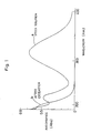
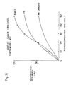
- Fig. 1 shows an absorption spectrum (a) of sample water (1 ppm in nitrogen concentration) containing NO 2 C 6 H 4 OH before irradiation with ultraviolet radiation and another absorption spectrum (b) measured after irradiation with ultraviolet radiation with blow of air.
- the sample water not yet irradiated with ultraviolet radiation has the maximum absorption in the vicinity of about 340 nm, and exhibits ultraviolet absorption of the unsaturated bonds having an absorption band of not more than 400 nm.
- the sample water is heated to 50 to 100 °C, since the photooxidative decomposition is remarkably facilitated by heating.
- a nitrogen compound and a phosphorus compound which are contained in the sample water are simultaneously oxidized to generate nitric acid ions and phosphoric acid ions from the nitrogen compound and the phosphorous compound respectively and the sample water is irradiated with the measuring beam so that the nitric acid ions and phosphoric acid ions can be sequentially measured in the same apparatus.
- the sample water is irradiated with the measuring beam so that the nitric acid ions and phosphoric acid ions can be sequentially measured in the same apparatus.
- the oxidizing velocity is increased when a photooxidation catalyst is employed, whereby the inventive analyzer can also be expected as a total nitrogen analyzer or a total phosphorus analyzer. It is also possible to elementarily analyze nitrogen and phosphorus, and hence the inventive analyzer can also be expected as an elementary analyzer for laboratory use.
- Silver halide is widely employed as a sensitive material for a photograph. Such silver halide has well-known light absorptivity of substantially absorbing the emission spectrum of a low pressure mercury lamp. However, it is not known that such silver halide has a catalytic action for oxidizing a nitrogen compound and a phosphorus compound which are contained in water.
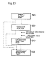
- An analyzer for also measuring an organic pollutant comprises a sample supply part for supplying a sample to be analyzed, an oxidative reaction unit receiving the sample from the sample supply part for oxidizing the same in a case of measuring a nitrogen compound or a phosphorus compound, a coloration reaction part for adding an ammonium molybdate solution and an L-ascorbic acid solution to the oxidized sample solution as color developers for measuring a phosphorous compound, and an absorbance measuring part for measuring absorbance of the sample solution.
- sample water in which a nitrogen compound and a phosphorus compound are simultaneously oxidized by the present invention to generate nitric acid ions and phosphoric acid ions from the nitrogen compound and the phosphorus compound respectively and non-oxidized sample water are irradiated with measuring beams, it is possible to measure nitric acid ions, phosphoric acid ions and an organic pollutant in a single apparatus. Consequently, common parts are increased in the measuring apparatus for three components, whereby the analyzer is reduced in cost and simplified in structure. Further, the analyzer is easy to maintain as compared with apparatuses installed for the respective components, whereby the space therefor can be saved.
- Fig. 2 shows an embodiment of the present invention in order of steps
- Fig. 3 illustrates a schematic structure of a measuring apparatus
- Figs. 4A and 4B illustrate an exemplary photooxidative decomposer for carrying out photooxidative decomposition.
- numeral 2 denotes a photooxidative decomposer which comprises heating means to be capable of heating sample water to 50 to 100 °C, as well as means for supplying oxygen or air to the sample water, and means for irradiating the sample water with ultraviolet radiation.
- the means for supplying oxygen or air to the sample water may or may not be provided.
- the sample water which is irradiated with ultraviolet radiation in the photooxidative decomposer 2 so that a nitrogen compound and a phosphorus compound are oxidized into nitric acid ions and phosphoric acid ions respectively is thereafter guided to a measuring vessel 8.
- Numeral 10 denotes an absorption photometer for measuring absorbance of the nitric acid ions contained in the sample water in the measuring vessel 8, and a quantity of color development by the phosphoric acid ions as absorbance after addition of color developers.
- an ammonium molybdate solution and an L-ascorbic acid solution are measured by meters 12 and 14 respectively and mixed with each other, to be supplied to the measuring vessel 8.
- the photooxidative decomposer 2 and the measuring vessel 8 are supplied with wash water to be washed therewith.
- Figs. 4A and 4B illustrate an exemplary photooxidative decomposer 2.
- Fig. 4A is a top plan view
- Fig. 4B is a front sectional view.
- Figs. 4A and 4B show an internal cylinder type decomposer comprising a reaction vessel 20 and low pressure mercury lamps 22 for emitting ultraviolet radiation, which are provided in the reaction vessel 20 to be directly in contact with sample water.
- the low pressure mercury lamps 22 emit shorter-wavelength ultraviolet radiation having luminance at 185 nm, for example.
- the reaction vessel 20 is provided on its bottom portion with an air inlet 24, a sample water inlet 26 and a sample water outlet 28, which are provided with couplings for enabling tube connection.
- a bypass 30 is provided on an upper portion of the reaction vessel 20.
- the bypass 30 is also provided with a coupling for tube connection.
- a cartridge heater 32 and a temperature sensor 34 are embedded in the reaction vessel 20 which is made of aluminum, so that the reaction vessel 20 is temperature-controlled at about 90 °C.
- the periphery of the reaction vessel 20 is covered with a heat insulating material 36 serving as a thermal insulator.
- the inner surface of the reaction vessel 20 is polished into a mirror structure, for multiple reflection of the ultraviolet radiation.
- the material for the reaction vessel 20 is not restricted to aluminum but the same may alternatively be prepared from stainless steel or glass.
- the inner surface of the reaction vessel 20 is preferably polished into a mirror structure also when the same is made of stainless steel.
- the reaction vessel 20 is made of Pyrex glass, on the other hand, the inner surface can be brought into a mirror structure by formation of a silver mirror or an aluminum evaporation film since the Pyrex glass does not transmit ultraviolet radiation.
- the reaction vessel 20 is made of ultraviolet transmittant glass, further, a silver mirror or an aluminum evaporation film can be formed on its outer surface to provide a mirror structure.
- the ultraviolet radiation source is not restricted to the low pressure mercury lamps 22, but may be prepared any light source such as an excimer laser, a deuterium lamp, a xenon lamp, an Hg-Zn-Pb lamp or the like, so far as the same can emit ultraviolet radiation with strong energy.
- the low pressure mercury lamp is preferable due to fitness as a monitor with a low cost and a long life.
- Each low pressure mercury lamp 22 is formed by an ultraviolet lamp of ultraviolet transmitting glass having a diameter of about 18 mm, which is worked into a U shape with a discharge current of 0.8 A and a discharge voltage of 10 V. When two such mercury lamps 22 are mounted on the reaction vessel 20 and dipped in the sample water, the water content in the reaction vessel 20 is about 100 ml.
- Numeral 23 denotes a power transformer for turning on the low pressure mercury lamps 22, and numeral 37 denotes a temperature controller for controlling the temperature of the reaction vessel 20.
- the low pressure mercury lamps 22 are turned on to irradiate the sample water which is stored in the reaction vessel 20 with ultraviolet radiation, while air is supplied from the air inlet 24 at about 0.1 litter/min.
- the sample water from which large soil is previously removed through a filter or the like, is supplied into the reaction vessel 20 through the sample inlet 26 while being measured.
- the sample water is heated to 90 °C and irradiated with ultraviolet radiation by the low pressure mercury lamps 22 for 20 minutes, with supply of air from the air inlet 24. It is conceivable that oxygen atoms and ozone are generated in the sample water which is stored in the reaction vessel 20 due to such ultraviolet irradiation, to oxidize a nitrogen compound and a phosphorus compound contained in the sample water for converting the same to nitric acid ions and phosphoric acid ions respectively and cutting unsaturated bonds of an organic compound if such an organic compound is present.
- the sample water which is stored in the reaction vessel 20 is partially or entirely taken out into the measuring vessel 8, so that the absorbance photometer 10 measures the nitric acid ions at a wavelength of 220 nm.
- an ammonium molybdate solution and an L-ascorbic acid solution are added to the measuring vessel 8 to color the sample water.
- the absorbance photometer 10 measures phosphoric acid ions contained in the ascolored solution at a wavelength of 880 nm.
- Table 1 shows recovery values of nitrogen compounds and phosphorus compounds contained in standard substances, which were measured by the aforementioned method.
- the recovery values show rates of the nitrogen compounds and the phosphorus compounds contained in the samples, which were oxidized into nitric acid ions and phosphoric acid ions respectively.
- a recovery value of 100 % indicates that the target nitrogen or phosphorus compound was entirely oxidized into nitric acid ions or phosphoric acid ions.
- Each standard substance contained nitrogen and phosphorus in concentration of 1 ppm (w/v) respectively.
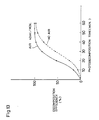
- Fig. 6 shows results of measurement of ultraviolet multiple reflection effects in a reaction vessel (a) having a mirror-finished inner surface for reflecting ultraviolet irradiation and a reaction vessel (b) having no mirror-finished inner surface.
- Sample water was prepared from an ammonium chloride solution containing 1 ppm of nitrogen, which was supplied at a temperature of 90 °C with supply of air at about 100 ml/min. As the result, a remarkable effect was attained in photooxidative decomposition reaction due to multiple reflection of ultraviolet radiation.
- the photooxidative decomposer 2 can be modified in various ways.
- the reaction vessel is preferably made of glass.
- Figs. 7A and 7B show an exemplary inner cylinder type photooxidative decomposer having a reaction vessel of glass.
- Fig. 7A is a top plan view
- Fig. 7B is a front sectional view.
- a reaction vessel 40 which is made of glass such as Pyrex is provided with an air inlet 24, a sample inlet 26 and a sample outlet 28 in its bottom portion and an overflow outlet 30 in its upper portion respectively.
- a protective vessel 42 of a metal having excellent heat conductivity is provided in contact with outer sides of the side and bottom portions of the reaction vessel 40, and a cartridge heater 32 and a temperature sensor 34 are embedded in the protective vessel 42.
- Other structures of this vessel 40 are identical to those shown in Figs. 4A and 4B.
- Low pressure mercury lamps 22 are mounted in the reaction vessel 40, while the protective vessel 42 is covered with a heat insulating material 36.
- the sample inlet 26 may be provided in the side or upper portion, in place of the bottom portion.
- the sample inlet 26 may be combined with the air inlet 24 to define a single inlet in a portion connected with the reaction vessel 20 or 40.
- Figs. 8A and 8B show an exemplary outer cylinder type photooxidative decomposer having an ultraviolet source which is arranged outside a reaction vessel.
- two low pressure mercury lamps 50 are arranged outside a reaction vessel 52, which is made of ultraviolet transmitting glass.
- Numeral 54 denotes a support member for the reaction vessel 52.
- An air inlet, a sample inlet, a sample outlet and an overflow outlet are simply illustrated.
- an outer cylinder 55 is provided outside the low pressure mercury lamps 50 for reflecting ultraviolet irradiation.
- Numeral 56 denotes a heater, which is provided outside the outer cylinder 55.
- the inner cylinder type decomposer Comparing inner and outer cylinder type photooxidative decomposers with each other, the inner cylinder type decomposer easily causes contamination of ultraviolet lamps although the same can effectively use radiation.
- the outer cylinder type decomposer has reverse characteristics.
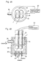
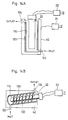
- Fig. 9 shows an exemplary photooxidative decomposer employing a photooxidation catalyst.
- a low pressure mercury lamp 22 for serving as an ultraviolet radiation source is mounted in the interior of a reaction vessel 40 which is made of Pyrex glass.
- the reaction vessel 40 can store about 150 ml of sample water 41 in the state provided with the low pressure mercury lamp 22.
- a stabilization power source (power transformer) 23 for the low pressure mercury lamp 22 has capacity of 54 W, a lamp current of 0.6 A, a primary voltage of 100 V and a secondary voltage of 190 V.
- An air inlet 24 is provided in a center of a bottom portion of the reaction vessel 40, to supply air into the reaction vessel 40 at 10 ml/min. for supplying oxygen and stirring the sample water 41.
- a sample water inlet 26 and a sample water outlet 28 are further provided in the bottom portion of the reaction vessel 40. The air inlet 24, the sample water inlet 26 and the sample water outlet 28 are provided with switch valves respectively.
- a bypass 30 is provided on an upper portion of the reaction vessel 40, to discharge an overflow.
- the reaction vessel 40 which is 50 mm in inner diameter, 55 mm in outer diameter and 120 mm in height, is provided therein with a photooxidation catalyst layer 110.
- the photooxidation catalyst layer 110 is formed by an Ag thin film having an AgCl thin film of about 50 ⁇ m in thickness on its surface, or an SiO 2 thin film containing TiO 2 having a thickness of about 2 ⁇ m, for example.
- a heat sink 42 which is formed by a protective vessel of aluminum is provided in contact with the outer side of the reaction vessel 40, in order to maintain sample water stored in the reaction vessel 40 at a constant temperature within a range of 50 to 100 °C.
- Two cartridge heaters (sheath heaters) 32 of about 30 W are embedded in the heat sink 42, while a temperature sensor 34 which is formed by a thermocouple is also embedded therein.
- a temperature controller 37 is set to adjust the temperature of the sample water at 90 °C, for example. The temperature of the sample water is abruptly increased to 90 °C by heat from the heat sink 42 and that generated in the low pressure mercury lamp 22.
- the ultraviolet radiation source is not restricted to the low pressure mercury lamp 22, but may alternatively be prepared from a light source such as an excimer laser, a deuterium lamp, a xenon lamp, an Hg-Zn-Pb lamp or the like, so far as the same can emit ultraviolet radiation with strong energy.
- a light source such as an excimer laser, a deuterium lamp, a xenon lamp, an Hg-Zn-Pb lamp or the like, so far as the same can emit ultraviolet radiation with strong energy.
- the low pressure mercury lamp 22 is turned on to irradiate the sample water which is stored in the reaction vessel 40 with ultraviolet radiation, while air is supplied from the air inlet 24.
- the decomposer shown in Fig. 9 is similar in operation to that shown in Figs. 4A and 4B, with addition of action of the photooxidation catalyst.
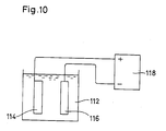
- Fig. 10 illustrates a method of forming an AgCl thin film, serving as an example of the photooxidation catalyst layer 110 shown in Fig. 9.
- An Ag thin plate 114 serving as a main material for forming a photooxidation catalyst is dipped as an anode in an NaCl solution 112 of about 1 mol, and a Pt thin plate 116 serving as a counter electrode is set to have the same surface area as the Ag thin plate 114.
- a voltage of about 0.3 V is applied from a dc power source 118 across the electrodes 114 and 116, the surface of the AgCl thin plate 114 is sufficiently plated in about 30 minutes, to form an AgCl thin film.
- An AgI thin film or an AgBr thin film can be prepared from an NaI solution or an NaBr solution similarly to the above.
- an Ag thin film may be formed on the inner surface of the reaction vessel 40 by silver mirror reaction so that the Ag thin film is electrolyzed in an NaCl solution similarly to Fig. 10, thereby forming an AgCl thin film.
- a coating of silver paste may be formed on the inner surface of the reaction vessel 40, to form an AgCl thin film similarly to the above.
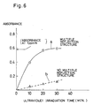
- Fig. 11 shows decomposition efficiency attained by a photooxidation catalyst of AgCl in comparison with those of other methods. A gas containing oxygen or ozone was not blown.
- the curve "AgCl” shows the result of investigation on sample water of 1.5 ppmN in concentration (concentration of 1.5 ppm in terms of nitrogen) with employment of (NH 4 ) 2 SO 4 as a typical example of hardly decomposable nitrogen compound in ammonium state through the photooxidative decomposer shown in Fig. 9.
- the curve "Pt” shows a case of employing a Pt thin film as a photooxidation catalyst, and a curve “NO CATALYST” shows a case of employing no photooxidation catalyst. It is understood from Fig.
- Fig. 11 shows that a remarkable catalytic effect was attained when AgCl was employed as the photooxidation catalyst. While Pt is known as an oxidation catalyst, Fig. 11 shows that the same has lower catalytic activity than AgCl in oxidation of a nitrogen compound and a phosphorus compound.
- a mixture containing the following components is prepared: Si(OC 2 H 5 ) 4 5.4ml C 2 H 5 OH 50ml 1N-HCl 20ml H 2 O 1.7ml 2 % hydroxypropyl cellulose 5ml
- a mixture containing the following components is prepared: Si(OC 2 H 5 ) 4 5.4ml C 2 H 5 OH 50ml 1N-HCl 20ml H 2 O 1ml tetraisopropyl titanate 5ml (Ti(OC 3 H 7 ) 4 )
- This mixture is homogenized and applied to the inner surface of the reaction vessel, dried at 100 °C to be gelated, and thereafter fired at 400 °C for 3 hours.
- a TiO 2 ⁇ SiO 2 thin film of about 2 ⁇ m in thickness is formed on the inner surface of the reaction vessel.
- a mixture containing the following components is prepared: Si(OC 2 H 5 ) 4 5.4ml C 2 H 5 OH 50ml 1N-HCl 20ml H 2 O 1.7ml 2 % hydroxypropyl cellulose 5ml chloroplatinic acid 100mg
- a mixture containing the following components is prepared: Si(OC 2 H 5 ) 4 5.4ml C 2 H 5 OH 50ml 1N-HCl 20ml H 2 O 1.7ml 2 % hydroxypropyl cellulose 5ml chloroplatinic acid 100mg RuO 2 25mg
- An SiO 2 thin film containing TiO 2 was formed on the inner surface of a reaction vessel of a photooxidative decomposer corresponding to that shown in Fig. 9 by the first method, and interfering substances of Br - and Cl - were added to a sample solution containing 1 ppmN of (NH 4 ) 2 SO 4 . 100 ppm of Br - was added in the form of NaBr - , and 2 percent by weight of Cl - was added in the form of NaCl.
- the sample conditions were set on the assumption of a case of measuring sea water as sample water, for confirming influences exerted by Br - and Cl - on the sea water.
- Table 2 shows results on photooxidation catalysts prepared from TiO 2 according to the present invention and from platinum as comparative example.
- bromine ions etc. contained in the sea water may serve as interference substances to reduce oxidation efficiency for a nitrogen compound and a phosphorus compound.
- TiO 2 is employed as the photooxidation catalyst, however, it is possible to implement an analyzer which is also suitable for analyzing sea water.
- Table 3 shows results of measurement of decomposition efficiency of TiO 2 photooxidation catalysts. Every catalyst attained excellent decomposition efficiency.
- Photooxidation Catalyst Metal Decomposition Efficiency at 1ppmN-(NH 4 ) 2 SO 4 TiO 2 (First method) 0.99 TiO 2 +Pt (Second method) 0.99 TiO 2 +Pt+RuO 2 (Fouth method) 0.93
- Figs. 12A and 12B show an exemplary photooxidative decomposer for irradiating sample water with ultraviolet radiation while not employing such oxidative gas.
- Fig. 12A is a top plan view
- Fig. 12B is a front sectional view.
- Low pressure mercury lamps 22 for emitting ultraviolet radiation are provided in a reaction vessel 40 which is made of glass such as Pyrex, to be directly in contact with sample water in the reaction vessel 40.
- the low pressure mercury lamps 22 emit ultraviolet radiation of a shorter wavelength having luminance at 185 nm, for example.
- a sample inlet 26 and a sample outlet 28 are provided in a bottom portion of the reaction vessel 40.
- a bypass 30 is provided on an upper portion of the reaction vessel 40, to discharge an overflow upon introduction of the sample water.
- a photooxidation catalyst 110 of AgCl or TiO 2 is provided on an inner wall surface of the reaction vessel 40, to be capable of being in contact with the sample water.
- a heat sink 42 of a heat conductive metal protective vessel is provided in contact with the outer sides of the reaction vessel 40 on side and bottom portions of the reaction vessel 40, while a cartridge heater 32 and a temperature sensor 34 are embedded in the heat sink 42.
- the outer side of the heat sink 42 is covered with a heat insulating material 36.
- the sample inlet 26 provided in the bottom portion may alternatively be provided in the side or upper portion.
- the sample inlet 26 may be combined with the air inlet to define a single inlet in a portion connected with the reaction vessel 40.
- Fig. 13 illustrates difference in oxidation efficiency between a case of blowing air into sample water and a case of not blowing air in ultraviolet irradiation. While higher oxidation efficiency is attained in the case of blowing air, high oxidation efficiency is also attained in the case of not blowing air due to an effect of a photooxidation catalyst. Thus, it is understood possible to attain sufficient oxidation efficiency without blowing oxidative gas such as air, by increasing a contact area between an oxidation catalyst and sample water.
- Oxidation efficiency for a nitrogen compound and a phosphorus compound is improved by applying ultraviolet radiation under presence of a photooxidation catalyst, whereby it is also possible to form a flow-type photooxidative decomposer for oxidizing sample water while continuously feeding the same.
- Figs. 14A to 14D show exemplary flow-type photooxidative decomposers.
- a photooxidation catalyst 110 of an AgCl thin film or a TiO 2 thin film is provided in the interior of a reaction vessel 120, to be in contact with sample water.
- a sample water inlet 122 and an outlet 124 are provided in a bottom portion and an upper end of the reaction vessel 120 respectively.
- a low pressure mercury lamp 22 is mounted in the reaction vessel 120, and turned on by a stabilizing power source 23.
- a heat sink 42 having a heater and a temperature sensor is provided outside the reaction vessel 120.
- a reaction vessel 130 provided with a photooxidation catalyst 110 on its inner surface is obliquely set while a sample water inlet 122 and an outlet 124 are provided in a bottom portion and an upper end thereof respectively.
- a low pressure mercury lamp 22 is mounted on a central portion of the reaction vessel 130 and a spiral plate 132 is provided between the low pressure mercury lamp 22 and the reaction vessel 130, so that sample water which is supplied from the inlet 122 is guided to the outlet 124 along the spiral plate 132 through the low pressure mercury lamp 22.
- a heat sink 42 having a heater and a temperature sensor is provided outside the reaction vessel 120.
- a reaction vessel 140 provided with a photooxidation catalyst 110 on its inner surface has a U-shaped section, while a sample water inlet 122 and an outlet 124 are provided in a bottom portion and an upper end thereof respectively.
- a U-shaped low pressure mercury lamp 142 is mounted on the interior of the reaction vessel 140 along its U-shaped section.
- a heat sink 42 having a heater and a temperature sensor is provided outside the reaction vessel 140.
- the photooxidative decomposer shown in Fig. 14D is different from those shown in Figs. 14A to 14C in a point that a catalyst is not formed by a thin film, but prepared from AgCl particles 152.
- a sample water inlet 122 and an outlet 124 are provided in a bottom portion and an upper end of the reaction vessel 150 respectively.
- a low pressure mercury lamp 154 is mounted on a central portion of the reaction vessel 150, and the AgCl particles 152 are charged between the low pressure mercury lamp 154 and the reaction vessel 150.
- An air inlet 156 is provided in a central portion of the bottom portion of the reaction vessel 150, to be capable of supplying air into the reaction vessel 150 in ultraviolet irradiation.
- the AgCl particles 154 are prepared by coating surfaces of spheres of glass or alumina with Ag to convert the same to AgCl, or coating such spheres with AgCl thin films, for example.
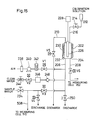
- Figs. 15 and 16 show an exemplary analyzer for a nitrogen compound and a phosphorus compound, which is formed by a batch type photooxidative decomposer.
- Fig. 15 shows a reaction part
- Fig. 16 shows a measuring part.
- Numeral 202 denotes a photooxidative decomposer for oxidizing a nitrogen compound and a phosphorus compound into nitric acid ions and phosphoric acid ions respectively by ultraviolet irradiation, which may be or may not be provided with a photooxidation catalyst on its inner surface.
- a supply pipe 206 for supplying sample water, air and clean wash water and a takeout pipe 208 for taking out sample water after oxidative reaction are connected to a bottom portion of an oxidative reaction vessel 204 of the photooxidative decomposer 202, while a discharge pipe 210 for discharging an overflow of the sample water, the wash water and air and a calibration solution supply pipe 216 for supplying a calibration solution 212 through a valve 214 are connected to an upper portion of the oxidative reaction vessel 204.
- the discharge pipe 210 is connected with a discharge valve V5, so that the sample water and the like are discharged through this valve V5.
- a low pressure mercury lamp 226 for emitting ultraviolet radiation of a shorter wavelength having luminance at 185 nm, for example, is arranged in the oxidative reaction vessel 204 as a light source for photooxidative decomposition.
- the low pressure mercury lamp 226 is turned on by a power source 228, to irradiate the sample water which is stored in the oxidative reaction vessel 204 with ultraviolet radiation.
- a heater 230 is provided in the oxidative reaction vessel 204 for maintaining the sample water which is stored therein at a prescribed temperature of 50 to 100 °C.
- the sample water can be controlled at the prescribed temperature by a temperature controller through a temperature sensor 232.
- the sample water stored in the oxidative reaction vessel 204 is temperature-controlled to 90 °C, for example.
- the heater 230 may be embedded in the oxidative reaction vessel 204 as a cartridge heater with the temperature sensor 232.
- the outer side of the oxidative reaction vessel 204 may be covered with a heat insulating material at need.
- a sample water passage is connected through a valve 234 and a pinch valve V3, in order to supply the sample water through the supply pipe 206 which is provided on the lower portion of the oxidative reaction vessel 204.
- a passage for discharging the sample water through a valve V4 is connected to the passage between the valves 234 and V3.
- An air supply passage is connected to the supply pipe 206 through a filter 238, a pump 240, a needled flow meter 242 and a valve V1, in order to supply air for aerating the sample water in oxidative reaction.
- a clean water supply passage is connected to the supply pipe 206 through a ball valve 244, an electromagnetic valve V2, a demineralizer 246 and a check valve 248, to supply clean water for washing passages of the oxidative reaction vessel 204, a measuring cell and the like.
- a discharge valve 250 is connected to the supply pipe 206, so that liquids remaining in the oxidative reaction vessel 204 and the supply pipe 206 can be discharged through this valve 250.
- the takeout pipe 208 which is provided on the bottom portion of the oxidative reaction vessel 204 is connected to a bottom portion of an absorbance measuring cell 252 through a valve V6.
- the absorbance measuring cell 252 can discharge water from its bottom portion through a valve V8, and a discharge pipe having a valve V7 is connected to its upper portion for discharging an overflow of the sample water and the wash water.
- the absorbance measuring cell 252 can make the sample water flow, and comprises a transmission window of quartz glass for transmitting measuring beams over ultraviolet and near infrared regions.
- a xenon flash lamp 254 is provided to apply measuring beams to the absorbance measuring cell 252.
- Deuterium and tungsten lamps can alternatively be employed on shorter and longer wavelength sides respectively as measuring light sources.
- the xenon lamp which can cover the range of wavelengths required for measurement is preferably employed since the structure is complicated when such two types of light sources are employed.
- a xenon flash lamp is preferable since a xenon lamp which is continuously turned on is heated to a high temperature and has a short life.
- the xenon flash lamp 254 has small heat generation, and a long life.
- Numeral 256 denotes a power source for the light source.
- the absorbance measuring cell 252 is connected with a color developer supply pipe 224 for supplying color developers 218 and 220 through a peristaltic pump 222.
- the color developers 218 and 220 which react with phosphoric ions, are prepared from an ammonium molybdate solution and an L-ascorbic acid solution respectively.
- the color developers 218 and 220 may be supplied to the oxidative reaction vessel 204, in place of the absorbance measuring cell 252.
- An ultraviolet transmittable quartz window is arranged on a measuring optical path of the absorbance measuring cell 252.
- the absorbance measuring cell 252 has a path length of 10 mm.
- a half mirror 262 is set on a transmission optical path of the absorbance measuring cell 252 for separating transmitted light, while a condenser lens 258 of quartz is arranged on the optical path between the absorbance measuring cell 252 and the half mirror 262, so that light transmitted through the absorbance measuring cell 252 is condensed on the half mirror 262.
- a calibration filter 260 is arranged on an optical path between the condenser lens 258 and the half mirror 262.
- the half mirror 260 is prepared from that whose wavelength characteristics are so set that reflected light has a wavelength of at least 800 nm and transmitted light has a wavelength of not more than 240 nm. Transmission and reflection optical paths of the half mirror 262 are adapted to measure a nitrogen compound and a phosphorus compound respectively.
- a silicon photodiode 266 is arranged on the transmission optical path of the half mirror 262 as a nitrogen side photodetector, while an optical filter 264 having a transmission wavelength of 220 nm is arranged on the optical path between the half mirror 262 and the photodiode 266.
- a silicon photodiode 270 is arranged on the reflection optical path of the half mirror 262 as a phosphorus side photodetector, and an optical filter 268 having a transmission wavelength of 880 nm is arranged on the optical path between the half mirror 262 and the photodiode 270.
- the optical filters 264 and 268 have half-band widths of 10 to 30 nm.
- the silicon photodiodes 266 and 270 serving as photodetectors are prepared from those having wide-range sensitivity over ultraviolet to near infrared regions.
- Preamplifiers 272 and 274 are connected to the photodiodes 266 and 270 for amplifying detection outputs thereof respectively, so that the detection outputs amplified by the preamplifiers 272 and 274 are incorporated in an operation part 278 through a pretreatment circuit 276.
- the pretreatment part 276 makes differential amplification and logarithmic amplification, and the operation part 278 calculates concentration values of the nitrogen compound and the phosphorus compound, to display the same on a display part 280.
- Numeral 284 denotes a power source for the operation part 278.
- the measured values can also be taken out as analog outputs, as values of DC 0 to 1 V or DC 4 to 20 mA, for example.
- Temperature control in measurement and sequence control for the respective electromagnetic valves (pinch and electromagnetic valves), the peristaltic pump and an air pump are carried out by a control part 282.
- the heater 230 of the photooxidative reaction part 202 is turned on to attain temperature control of 90 °C.
- the power source 228 for the light source is also turned on to stabilize the ON state of the low pressure mercury lamp 226.
- valves V3 and V4 are previously brought into OFF and ON states respectively for discharging. Thereafter the valves V3 and V4 are brought into ON and OFF states respectively while the valve 250 is brought into an OFF state to introduce the sample water into the reaction vessel 204, and an overflow of the sample water is discharged through the valve V5. Thereafter the valves V3 and V4 are brought into OFF and ON states respectively. Then, the valve V1 is brought into an ON state to introduce air into the reaction vessel 204, and the sample water held by the photooxidative reaction part 202 is irradiated with ultraviolet radiation for about 20 minutes with aeration, to make simultaneous oxidative reaction of a nitrogen compound and a phosphorus compound contained in the sample water.
- valve V6 After completion of photooxidative reaction, the valve V6 is brought into an ON state to introduce half the sample water from the oxidative reaction vessel 204 into the measuring cell 252, and an overflow from the measuring cell 252 is discharged through the valve V7.
- the sample water held in the measuring cell 252 is irradiated with a measuring beam from the light source 254, to be subjected to measurement of nitric acid ion concentration at a wavelength of 220 nm.
- the valve V8 After photoabsorption measurement of the nitric acid ions is completed in the measuring cell 252, the valve V8 is brought into an ON state to discharge the sample water from the measuring cell 252. At this time, the valve V6 is in an OFF state. After the sample water is completely discharged from the measuring cell 252, the valves V8 and V6 are brought into OFF and ON states respectively to introduce the remaining sample water from the photooxidative reaction part 202 into the sample cell 252, and an overflow is discharged through the valve V7.
- the color developers 218 and 220 are added to the measuring cell 252 for color development. Phosphoric acid ions are measured at a wavelength of 880 nm. After the measurement, the valve V8 is brought into an ON state to discharge the sample water from the measuring cell 252.
- valve V2 is brought into an ON state while the valve V6 remains in the OFF state, to supply clean water to the oxidative reaction vessel 204 to wash the same.
- the valve V6 is brought into an ON state to supply the wash water also to the measuring cell 252 through the oxidative reaction vessel 204, to wash the same.
- the valves V8 and V7 are brought into OFF and ON states respectively.
- supply of the wash water is stopped and the valve V8 is brought into an ON state to discharge the wash water from the measuring cell 252.
- the wash water is entirely discharged from the measuring system.
- Figs. 17A and 17B illustrate exemplary analyzers for nitrogen compounds and phosphorus compounds employing flow-type photooxidative decomposers.
- the flow-type decomposers are different in passage structure from the batch type decomposer.
- sample water from a photooxidative decomposer 300 is continuously fed to a measuring cell 302, so that absorbance of nitric ions is measured by an absorbance spectrometer 304 in nitrogen measurement with no operation of a pump 212 and no supply of color developers 218 and 220.
- the pump 212 operates to supply the color developers 218 and 220 to a passage between the photooxidative decomposer 300 and the measuring cell 302, so that absorbance of the as-colored solution is measured by the absorbance spectrometer 304.
- a sequence control part 306 controls the operation of the pump 212 and switching of measuring wavelengths of the absorbance spectrometer 304.
- sample water from a photooxidative decomposer 300 is separated into two passages, and one of the passages is directly guided to a measuring cell 302N so that absorbance of nitric acid ions is measured by an absorbance spectrometer 304N.
- Color developers 218 and 220 are regularly supplied to the other passage from a pump 212, so that absorbance of the sample water which is introduced into a measuring cell 302P is measured by an absorbance spectrometer 304P.
- Fig. 18 shows a reaction part of Fig. 17A in detail.
- the sample water is fed by a pump 310, and adjusted to a prescribed flow rate by an adjusting vessel 312.
- the sample water is guided from the adjusting vessel 312 to a flow-type photooxidative decomposer 300.
- the photooxidative decomposer 300 is that illustrated in Fig. 14A to 14D.
- a sample water passage from the photooxidative decomposer 300 is connected to a manifold 322.
- a clean water supply path meets the sample water passage at the manifold 322 through a ball valve 314, an electromagnetic valve 316, a demineralizer 318 and a check valve 320.
- Color developers 218 and 220 are supplied through a pump 212, to meet the manifold 322 through a valve 324.
- a passage from the manifold 322 is guided to the measuring part shown in Fig. 16.
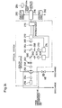
- Fig. 19 illustrates the pretreatment part 276 and the operation part 278 provided in the measuring part shown in Fig. 16 in detail.
- a detection signal from the nitrogen side photodiode 266 is amplified by the preamplifier 272, and a logarithmic amplifier 284 is connected to the output side of the preamplifier 272 in order to convert the amplified output to a logarithmic value.
- the output of the logarithmic amplifier 284 is converted to a current value by a V-I converter 296, to be taken out as an output.
- logarithmic amplifiers 286 and 288 are connected in parallel with the output side of the preamplifier 274, in order to convert a detection output amplified by the preamplifier 274 to a logarithmic value.
- the output of the logarithmic amplifier 286 is also converted to a current value by a V-I converter 400, so that the output can be taken out. Since the relations between concentration values and absorbance values of a nitrogen compound and a phosphorus compound comply with the Lambert-Beer's law, the signals from the photodiodes 266 and 270 are logarithmically converted so that the output signals are proportionate to the concentration values.
- Numeral 290 denotes a nitrogen side differential amplifier, which can amplify the difference between the logarithmic values converted by the logarithmic amplifiers 284 and 286 to take out the output from a V-I converter 298 as a nitrogen side measurement value.
- the logarithmically converted value from the logarithmic amplifier 286 is also held by a holding circuit 292, while a phosphorus side differential amplifier 294 receives a phosphorus side measurement value from the logarithmic amplifier 288 as well as the output of the logarithmic amplifier 286 in phosphorus side measurement held in the holding circuit 292 to amplify the difference therebetween, for outputting the result from a V-I converter 402 as a phosphorus side measurement value.
- a detection signal by the photodiode 270 in measurement of nitrogen compound concentration is held by the holding circuit 292 as reference light, light reflected by the half mirror 262 through a measurement solution (obtained by adding color developers to the sample water) in phosphorus compound measurement serves as sample light, and the difference between the signal from the logarithmic amplifier 288 and that held by the holding circuit 292 is amplified by the differential amplifier 294 and outputted from the V-I converter 402 as a phosphorus compound concentration measurement value.
- Samples were irradiated with ultraviolet radiation under presence of photooxidative catalysts with flow of air at about 10 ml/min., to be subjected to measurement of nitrogen compounds and phosphorus compounds according to the present invention.
- Table 4 shows the results of standard samples, which were prepared by dissolving reagents in pure water.
- Standard Sample Prepared Concentration Measured Concentration Ammonium sulfate (NH 4 ) 2 SO 4 1.5ppmN 1.47ppmN Sulfanilic acid amide NH 2 C 6 H 4 SO 2 NH 2 1.5ppmN 1.58ppmN L-Sodium glutamate C 5 H 8 NO 4 Na ⁇ H 2 O 1.5ppmN 1.59ppmN Adenisine-5-monophosphate C 10 H 14 N 5 O 7 P 0.8ppmP 0.83ppmP Sodium glycerol phosphate HOCH 2 CH(OH)CH 2 OPO 3 Na ⁇ 6H 2 O 0.8ppmP 0.86ppmP Sodium phenylphosphate C 6 H 5 Na 2 PO 4 ⁇ 2H 2 O 0.8ppmP 0.84ppmP
- Table 5 shows measurement values of waste water samples prepared by diluting factory effluents with pure water, in comparison of those measured by official and inventive methods.
- Sample Official method Inventive method Food factory effluent 9.19ppmN 0.076ppmP 9.68ppmN 0.080ppmP Dye factory effluent 4.64ppmN 1.8ppmP 6.78ppmN 1.63ppmP Milk factory effluent 15.7ppmN 2.7ppmP 17.2ppmN 2.89ppmP Sewage 27.8ppmN 1.0ppmP 26.8ppmN 1.30ppmP Machine factory effluent 13.1ppmN 0.40ppmP 14.2ppmN 0.500ppmP
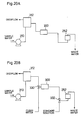
- Figs. 20A and 20B show embodiments of inventive analyzers for feeding sample water through vertical differences between passages.
- an adjusting vessel 312 is arranged at the highest position and a flow-type photooxidative decomposer 300 to be supplied with sample water from the adjusting vessel 312 is arranged at a lower position, while a measuring cell 252 to be supplied with the sample water photooxidized in the photooxidative decomposer 300 is arranged at a further lower position.
- the sample water is fed to the adjusting vessel 312 by a pump 310, and adjusted to be at a prescribed flow rate.
- the sample water fed from the adjusting vessel 312 is guided to the photooxidative decomposer 300 by the head.
- the sample water photooxidatively decomposed by the photooxidative decomposer 300 flows to the measuring cell 252 also by the head, to be discharged to a drain from the measuring cell 252.
- a clean water supply passage is connected to a passage between an adjusting vessel 312 and a photooxidative decomposer 300 through a switching valve 330, while a standard solution supply passage is connected to a passage between the photooxidative decomposer 300 and a measuring cell 252 through a switching valve 332.
- the switching valves 330 and 332 are set on sample water passages when measurement is carried out with flow of the sample water, while the switching valve 330 is switched to the clean water supply passage when clean water is supplied for washing the passage and the switching valve 332 is switched to the standard solution supply passage when a standard solution is measured.
- the sample water flows from the adjusting vessel 312 toward a downstream side by the head also in this case.
- Figs. 21A and 21B show absorption spectra in measurement of nitric acid ions and phosphoric acid ions.
- Fig. 21A standard water samples containing KNO 3 in concentration values of 5 ppm, 10 ppm and 20 ppm respectively were measured as standard samples of nitric acid ions. Due to absorbance of not more than 240 nm, light of 220 nm in wavelength is selected by the optical filter 264.
- a standard sample was prepared by adding molybdenum blue (solutions of ammonium molybdate and L-ascorbic acid) as a color developer to sample water containing 3 ppm of KH 2 PO 4 . Light of 880 nm in wavelength is selected by the optical filter 268 for phosphoric acid ion measurement.
- the reaction vessel may be of another type so far as the same simultaneously oxidizes a nitrogen compound and a phosphorus compound to generate nitric acid ions and phosphoric acid ions respectively.
- Fig. 22 shows such an embodiment that a measuring cell 252a also serves as a photooxidative decomposer.
- the measuring cell 252a has a window of ultraviolet transmitting quartz glass, so that light of a xenon lamp 254a serving both as a photooxidative reaction light source and an absorbance measuring light source is incident upon the window.
- the measuring cell 252a is supplied with sample water and air, as well as clean water for washing.
- a heater 230a and a temperature detector 232a are provided on the measuring cell 252a, in order to heat the sample water in photooxidative reaction.
- Color developers 218 and 220 for phosphoric acid ion measurement are supplied to the measuring cell 252a through a peristaltic pump 222.
- the light source 254a is formed by a continuous emission xenon lamp, since the same requires a large light quantity for serving both as a photooxidative reaction light source and an absorbance measuring light source.
- the sample water is introduced into the measuring cell 252a and air is blown into the sample water to aerate the same, thereby causing photooxidative reaction over 20 to 30 minutes. Thereafter absorbance measurement at 220 nm is first carried out to measure nitrogen compound concentration. Thereafter constant amounts of the color developers 218 and 220 are injected into the measuring cell 252a and stood still for about 5 minutes, and phosphorus compound concentration is measured by absorbance measurement at 880 nm.
- Figs. 23 to 25 show embodiments for measuring nitrogen compounds and phosphorus compounds as well as organic pollutants by single measuring apparatuses.
- Fig. 23 shows a basic structure of one of the embodiments.
- This measuring apparatus is mainly formed by a sample supply part 520 for supplying a sample to be measured, an oxidative reactor 530 receiving the sample from the sample supply part 520 and oxidizing the same in measurement of a nitrogen compound or a phosphorus compound, a coloration reaction part 540 for adding an ammonium molybdate solution and an L-ascorbic acid solution to the oxidized sample solution in measurement of a phosphorus compound, and an absorbance measuring part 550 for measuring absorbance of each sample solution.
- a sample is supplied from the sample supply part 520 to the absorbance measuring part 550.
- the oxidative reactor 530 and the coloration reaction part 540 merely passes the sample solution or directly supply the sample to the absorbance measuring part 550 through a bypass passage.
- the absorbance measuring part 550 measures absorbance at a measuring wavelength of 254 nm, for example, to measure the organic pollutant.
- a sample is fed to the oxidative reactor 530 so that the nitrogen compound is oxidized to nitric acid ions, and the sample solution oxidized in the oxidative reactor 530 is passed through the coloration reaction part 540 or guided to the absorbance measuring part 550 through the bypass passage, so that the nitric acid ions are measured at a measuring wavelength of 220 nm.
- a sample is fed to the oxidative reactor 530 so that the phosphorus compound is oxidized to phosphoric acid ions and colored by addition of color developers in the coloration reaction part 540, and thereafter the phosphoric acid ions are measured by the absorbance measuring part 550 at a measuring wavelength of 880 nm.
- An exemplary reaction part comprising sample supply part 520 and oxidative reactor 530 is that shown in Fig. 15, and a measuring part comprising coloration reaction part 540 and absorbance measuring part 550 is that shown in Fig. 24.
- the absorbance measuring cell 252 can make sample water flow, and comprises a transmission window of quartz glass for transmitting measuring beams over ultraviolet and near infrared regions.
- a xenon flash lamp 254 is provided in order to irradiate the absorbance measuring cell 252 with a measuring beam.
- Deuterium and tungsten lamps may alternatively be employed on shorter and longer wavelength sides respectively as measuring light sources.
- Numeral 256 denotes a power source for the light source.
- While means for adding color developers is provided on the absorbance measuring cell 252, the same may alternatively provided on an oxidative reaction vessel 204.
- the absorbance measuring cell 252 has the ultraviolet transmittable quartz window which is arranged on a measuring optical path, and its optical path length is 10 mm.
- a half mirror 500 is arranged on a transmission optical path of the absorbance measuring cell 252 for separating transmitted light, and a condenser lens 258 of quartz is arranged on an optical path between the absorbance measuring cell 252 and the half mirror 500, so that light transmitted through the absorbance measuring cell 252 is condensed on the half mirror 262.
- a calibration filter 260 is arranged on an optical path between the condenser lens 258 and the half mirror 500.
- the half mirror 500 has no wavelength characteristics, but is merely adapted to separate light transmitted through the absorbance measuring cell 252 into reflected light and transmitted light.
- a silicon photodiode 504 is arranged on a reflection optical path of the half mirror 500 in order to measure the organic pollutant, while an optical filter 502 having a transmission wavelength of about 254 nm is arranged on an optical path between the half mirror 500 and the photodiode 504.
- the half mirror 262 is further arranged on a transmission optical path of the half mirror 500.
- An optical system of reflection and transmission optical paths of the half mirror 262 and a signal processing system are similar to those shown in Fig. 16.
- valves V3 and V4 are brought into OFF and ON states to discharge sample water.
- valves V3, V4, 250, V5 and V6 are brought into ON, OFF, OFF, OFF and ON states respectively for introducing sample water into the measuring cell 252 through the oxidative reaction vessel 204 while discharging an overflow from the measuring cell 252.
- the sample held in or flowing in the sample cell 252 is irradiated with a measuring beam from the light source 254, so that the organic pollutant is measured at a wavelength of 254 nm.
- a nitrogen compound and a phosphorus compound are measured by an operation which is identical to that of the embodiment shown in Figs. 15 and 16.
- a photooxidative decomposer 202 may be formed by providing TiO 2 or silver halide in the oxidative reaction vessel 204 as a photooxidation catalyst, to increase the reaction rate.
- the sample water is guided to the measuring cell 252 through the reaction vessel 204 also in measurement of the organic pollutant.
- measuring cells 252 and 510 are provided independently of each other for measuring a nitrogen compound and a phosphorus compound, and an organic pollutant respectively. While a reaction part is formed by that shown in Fig. 15, the sample water supply passage 508 shown by chain lines in Fig. 15 is branched from a portion between the valves 234 and V3 so that sample water is directly guided to the measuring cell 510 without passing through the reaction vessel 204.
- a light source 254 for measurement is utilized by the measuring cells 252 and 510 in common, while optical systems 268 and 270 for nitrogen compound measurement and optical systems 264 and 266 for phosphorus compound measurement are arranged on a transmission optical path of the measuring cell 252, and an optical filter 502 and a silicon photodiode 504 are arranged on a transmission optical path of the measuring cell 510 for carrying out measurement at an absorption wavelength of an organic pollutant through a condenser lens 512 and a calibration filter 514.
- the measuring cells 252 and 510 are provided independently of each other, whereby it is possible to measure the organic pollutant in continuation. A nitrogen compound and a phosphorus compound are intermittently measured.
- the inventive analytical method may not be necessarily employed under conditions for attaining recovery of 100 %.
- the method can also be employed in a state of recovery of less than 100 %, by previously measuring a constant correlation between analytical values measured by a conventionally established method employing oxidation with an oxidant and absorptiometry and in the inventive method in a state with recovery of less than 100 %.
Landscapes
- Life Sciences & Earth Sciences (AREA)
- Chemical & Material Sciences (AREA)
- Health & Medical Sciences (AREA)
- Physics & Mathematics (AREA)
- Pathology (AREA)
- Analytical Chemistry (AREA)
- Biochemistry (AREA)
- General Health & Medical Sciences (AREA)
- General Physics & Mathematics (AREA)
- Immunology (AREA)
- Engineering & Computer Science (AREA)
- Medicinal Chemistry (AREA)
- Food Science & Technology (AREA)
- Molecular Biology (AREA)
- Chemical Kinetics & Catalysis (AREA)
- Plasma & Fusion (AREA)
- Investigating Or Analyzing Non-Biological Materials By The Use Of Chemical Means (AREA)
Claims (23)
- Ein analytisches Verfahren zum Analysieren einer Stickstoffverbindung und einer Phosphorverbindung, die in Wasser enthalten sind, mit folgenden Schritten (A) bis (C):(A) einem Oxidationsschritt des Bestrahlens des Probenwassers mit einer ultravioletten Strahlung, während das Probenwasser auf 50 bis 100°C erwärmt wird;(B) einem Schritt des Messens von Stickstoffsäure-Ionen, die in dem oxidierten Probenwasser enthalten sind, durch eine Absorptionsmessung; und(C) einem Schritt des Hinzufügens eines Farbentwicklers, der selektiv mit Phosphorsäure-Ionen reagiert, zu dem oxidierten Probenwasser, und des Messens der derart gefärbten Lösung durch eine Absorptionsmessung.
- Ein analytisches Verfahren gemäß Anspruch 1, bei dem
der Oxidationsschritt des Bestrahlens des Probenwassers mit einer ultravioletten Strahlung durchgeführt wird, während ein Gas, das Sauerstoff oder Ozon enthält, in das Probenwasser geblasen wird. - Ein analytisches Verfahren gemäß Anspruch 1, bei dem
der Oxidationsschritt des Bestrahlens des Probenwassers mit einer ultravioletten Strahlung in der Gegenwart eines Photooxidations-Katalysators durchgeführt wird. - Ein analytisches Verfahren gemäß Anspruch 3, bei dem
der Photooxidations-Katalysator TiO2 oder Silberhalid ist. - Eine Photooxidations-Zerlegungsvorrichtung (2) zum gleichzeitigen Oxidieren einer Stickstoffverbindung und einer Phosphorverbindung, die in einem Probenwasser enthalten sind, zum Erzeugen von Stickstoffsäure-Ionen und Phosphorsäure-Ionen aus der Stickstoffverbindung bzw. der Phosphorverbindung, mit folgenden Merkmalen:einem Oxidationsreaktionsgefäß (20; 40; 52; 120; 130; 140; 150) mit einem Probenwasser-Einlaß und einem -Auslaß (26, 28);einer Heizeinrichtung (34; 56; 32, 42) zum Erwärmen des Probenwassers, das in dem Oxidationsreaktionsgefäß enthalten ist, auf 50 bis 100°C; undeiner Ultraviolettstrahlungsquelle (22, 50, 142, 154) zum Bestrahlen des Probenwassers, das in dem Oxidationsreaktionsgefäß enthalten und durch die Heizeinrichtung erwärmt ist, mit einer Ultraviolettstrahlung, um sowohl eine Stickstoffverbindung als auch eine Phosphorverbindung, die in dem Probenwasser enthalten sind, in Stickstoffsäure-Ionen bzw. Phosphorsäure-Ionen zu oxidieren.
- Eine Photooxidations-Zerlegungsvorrichtung gemäß Anspruch 5, bei der
das Oxidationsreaktionsgefäß (20, 40, 52, 150) eine Gaszuführungsöffnung (24, 156) zum Blasen von Gas, das Sauerstoff oder Ozon enthält, in das Probenwasser aufweist. - Eine Photooxidations-Zerlegungsvorrichtung gemäß Anspruch 5, bei der
das Oxidationsreaktionsgefäß (40, 52, 120, 130, 140, 150) mit einem Photooxidations-Katalysator-Dünnfilm (110) auf seiner inneren Oberfläche versehen ist, oder mit einem Photooxidations-Katalysator (152) in seinem Inneren beladen ist. - Eine Photooxidations-Zerlegungsvorrichtung gemäß Anspruch 7, bei der
der Photooxidations-Katalysator (110, 152) Silberhalid ist. - Eine Photooxidations-Zerlegungsvorrichtung gemäß Anspruch 7, bei der
der Photooxidations-Katalysator (110) Titandioxid ist. - Eine Photooxidations-Zerlegungsvorrichtung gemäß Anspruch 9, bei der
das Titandioxid Anatas-Titandioxid ist. - Eine Photooxidations-Zerlegungsvorrichtung gemäß Anspruch 7, bei der
der Photooxidations-Katalysator eine Verbindung ist, die aus Anatas-Titanoxid, das Platin enthält, besteht. - Eine Photooxidations-Zerlegungsvorrichtung gemäß Anspruch 7, bei der
der Photooxidations-Katalysator eine Verbindung ist, die aus Anatas-Titandioxid, das Platin und Rutheniumdioxid enthält, besteht. - Eine Photooxidations-Zerlegungsvorrichtung gemäß Anspruch 7, bei der
der Photooxidations-Katalysator-Dünnfilm auf einer inneren Oberfläche des Oxidationsreaktionsgefäßes gebildet ist, wobei der Photooxidations-Katalysator-Dünnfilm aus einem Beschichtungsfilm besteht, der durch das Brennen eines Sols aus Siliziumalkoxid, das Anatas-Titandioxid-Pulver und den Zusatz von Rutheniumdioxid-Pulver und Chlorplatin-Säure zu demselben enthält, vorbereitet ist. - Eine Photooxidations-Zerlegungsvorrichtung gemäß Anspruch 5, bei der
das Oxidationsreaktionsgefäß (40) mit einem Photooxidations-Katalysator-Dünnfilm (110) auf seiner inneren Oberfläche versehen ist, oder mit einem Photooxidations-Katalysator in seinem Inneren beladen ist, wobei das Oxidationsreaktionsgefäß einen Kanal aufweist, durch den das Probenwasser nicht durchgehend zugeführt und nicht durchgehend entnommen wird. - Eine Photooxidations-Zerlegungsvorrichtung gemäß Anspruch 5, bei der
das Oxidationsreaktionsgefäß (120, 130, 140, 150) mit einem Photooxidations-Katalysator-Dünnfilm (110) auf seiner inneren Oberfläche versehen ist oder mit einem Photooxidations-Katalysator (152) in seinem Inneren beladen ist, wobei das Oxidationsreaktionsgefäß einen Kanal aufweist, durch den das Probenwasser durchgehend zugeführt und durchgehend entnommen wird. - Ein Analysator zum Analysieren einer Stickstoffverbindung und einer Phosphorverbindung, die in Wasser enthalten sind, mit folgenden Merkmalen:einem Oxidationsreaktionsgefäß (202, 300) zum gleichzeitigen Oxidieren einer Stickstoffverbindung und einer Phosphorverbindung, die in dem Probenwasser enthalten sind, zum Erzeugen von Stickstoffsäure-Ionen und Phosphorsäure-Ionen aus der Stickstoffverbindung bzw. der Phosphorverbindung durch das Bestrahlen des Probenwassers in dem Oxidationsreaktionsgefäß (202, 300) mit einer Strahlung von einer Ultraviolettstrahlungseinrichtung (22, 50, 142, 154);einer Absorptions-Meßzelle (252) aus Quarzglas, die mit dem Oxidationsreaktionsgefäß durch einen Kanal gekoppelt ist, um mit dem Probenwasser von dem Oxidationsreaktionsgefäß versorgt zu werden;einem Farbentwickler-Hinzufügungskanal (224) zum Hinzufügen eines Farbentwicklers, der mit den Phosphorsäure-Ionen selektiv reagiert, zu dem Oxidationsreaktionsgefäß oder der Absorptions-Meßzelle;einem Lichtquellenabschnitt (254) zum Bestrahlen der Absorptions-Meßzelle mit einer ultravioletten Strahlung und einer nahezu infraroten Strahlung als Meßstrahl;einer Trenneinrichtung (262), die in einem optischen Meßstrahl-Transmissionsweg der Absorptions-Meßzelle vorgesehen ist, um Licht, das durch dieselbe transmittiert wird, in zwei optische Wege zu trennen;einem ersten optischen System (264, 266), das in einem der zwei getrennten optischen Wege vorgesehen ist, zum Trennen einer Absorptions-Wellenlänge, die für die Stickstoffsäure-Ionen spezifisch ist, und zum Erfassen von Licht der Wellenlänge als dem Probenlicht der Stickstoffsäure-Ionen;einem zweiten optischen System (268, 270), das in dem zweiten der getrennten optischen Wege vorgesehen ist, zum Auswählen einer Absorptions-Wellenlänge, die spezifisch für den Farbentwickler, der mit den Phosphorsäure-Ionen reagiert, ist, und zum Erfassen von Licht dieser Wellenlänge als Probenlicht der Phosphorsäure-Ionen; undeinem arithmetischen Verarbeitungsabschnitt (278) zum Berechnen der Stickstoffverbindungskonzentration und der Phosphorverbindungskonzentration auf der Basis von Erfassungssignalen von dem ersten und dem zweiten optischen System.
- Ein Analysator gemäß Anspruch 16, bei dem
das Oxidationsreaktionsgefäß (202) eine Gaszuführungsöffnung zum Blasen von Gas, das Sauerstoff oder Ozon enthält, in das Probenwasser aufweist. - Ein Analysator gemäß Anspruch 16, bei dem
das Oxidationsreaktionsgefäß (202) entweder einen Silberhalid-Katalysator, einen Titandioxid-Katalysator, einen Titandioxid-Katalysator, der Platin enthält, das zu demselben hinzugefügt ist, oder einen Titandioxid-Katalysator, der Platin und Rutheniumdioxid, die zu demselben hinzugefügt sind, als einen Photooxidations-Katalysator aufweist. - Ein Analysator gemäß Anspruch 18, bei dem
das Oxidationsreaktionsgefäß (202) eine Gaszuführungsöffnung zum Blasen eines Gases, das Sauerstoff oder Ozon enthält, in das Probenwasser aufweist. - Ein Analysator gemäß Anspruch 18, bei dem
die Absorptions-Meßzelle (252) an einer Position angeordnet ist, die tiefer ist als die des Oxidationsreaktionsgefäßes (300), wobei in einem Kanal für die Entladung des Probenwassers aus dem Oxidationsreaktionsgefäß durch die Absorptions-Meßzelle keine Pumpe angeordnet ist, so daß das Probenwasser durch die Druckhöhe des Wassers übertragen wird. - Ein Analysator zum Analysieren einer Stickstoffverbindung und einer Phosphorverbindung, die in Wasser enthalten sind, gemäß Anspruch 16, bei dem
das Oxidationsreaktionsgefäß (202, 300) und die Absorptions-Meßzelle (252) durch ein einziges Gefäß (252a) gebildet sind, das zumindest ein Fenster aus für ultraviolette Strahlung durchlässigem Quarzglas aufweist, wobei der Lichtquellenabschnitt (254a) sowohl als eine Ultraviolettstrahlungsquelle zum Bestrahlen des Probenwassers als auch als eine Lichtquelle zum Liefern des Meßstrahls dient. - Ein Analysator zum Analysieren einer Stickstoffverbindung, einer Phosphorverbindung und ferner eines organischen Schadstoffes, die in Wasser enthalten sind, gemäß Anspruch 16, bei demdie Trennungseinrichtung (262, 500) vorgesehen ist, um Licht, das durch dieselbe transmittiert wird, in drei optische Wege zu trennen;wobei der Analysator ferner ein drittes optisches System (502, 504) aufweist, das in einem dritten der getrennten optischen Wege vorgesehen ist, zum Erfassen von Licht einer Absorptions-Wellenlänge, die spezifisch für einen organischen Schadstoff ist, als Probenlicht des organischen Schadstoffes; undwobei der arithmetische Verarbeitungsabschnitt (278) zum Berechnen der Stickstoffverbindungskonzentration, der Phosphorverbindungskonzentration und der Konzentration des organischen Schadstoffes auf der Basis von Erfassungssignalen von dem ersten, dem zweiten und dem dritten optischen System vorgesehen ist.
- Ein Analysator zum Analysieren einer Stickstoffverbindung, einer Phosphorverbindung und ferner eines organischen Schadstoffes, die in Wasser enthalten sind, gemäß Anspruch 16, der ferner folgende Merkmale aufweist:der Analysator ferner folgendes Merkmal aufweist:eine zweite Absorptions-Meßzelle (510) aus Quarzglas, der das Probenwasser zugeführt wird; wobeider erste Lichtquellenabschnitt (254) zum Bestrahlen der ersten Absorptions-Meßzelle mit einer ultravioletten Strahlung und einer nahezu infraroten Strahlung und zum Bestrahlen der zweiten Absorptions-Meßzelle mit einer ultravioletten Strahlung als Meßstrahlen vorgesehen ist; wobeiein drittes optisches System (502, 504), das in einem Transmissionsweg für einen der Meßstrahlen von dem Lichtquellenabschnitt durch die zweite Absorptions-Meßzelle vorgesehen ist, zum Erfassen von Licht einer Absorptions-Wellenlänge, die für einen organischen Schadstoff spezifisch ist, als Probenlicht des organischen Schadstoffes; und wobeider arithmetische Verarbeitungsabschnitt (278) zur Berechnung der Stickstoffverbindungskonzentration, der Phosphorverbindungskonzentration und der Konzentration des organischen Schadstoffes auf der Basis von Erfassungssignalen von dem ersten, dem zweiten und dem dritten optischen System vorgesehen ist.
Applications Claiming Priority (10)
| Application Number | Priority Date | Filing Date | Title |
|---|---|---|---|
| JP19796593A JP3269196B2 (ja) | 1993-07-14 | 1993-07-14 | 水中の窒素化合物及びリン化合物の分析装置 |
| JP197964/93 | 1993-07-14 | ||
| JP197965/93 | 1993-07-14 | ||
| JP19796493A JP3269195B2 (ja) | 1993-07-14 | 1993-07-14 | 水中の窒素化合物及びリン化合物の分析方法並びに光酸化分解装置 |
| JP33004293A JP3291879B2 (ja) | 1993-11-30 | 1993-11-30 | 光酸化分解装置、それを利用した水中の窒素化合物及びリン化合物の分析方法並びに装置 |
| JP330042/93 | 1993-11-30 | ||
| JP11423694A JP3264090B2 (ja) | 1994-04-30 | 1994-04-30 | 窒素化合物、リン化合物及び有機汚濁物質の計測装置 |
| JP114236/94 | 1994-04-30 | ||
| JP12676994A JP3237400B2 (ja) | 1994-05-16 | 1994-05-16 | 水中の窒素化合物及びリン化合物の分析装置 |
| JP126769/94 | 1994-05-16 |
Publications (2)
| Publication Number | Publication Date |
|---|---|
| EP0634646A1 EP0634646A1 (de) | 1995-01-18 |
| EP0634646B1 true EP0634646B1 (de) | 1999-01-27 |
Family
ID=27526630
Family Applications (1)
| Application Number | Title | Priority Date | Filing Date |
|---|---|---|---|
| EP94110835A Expired - Lifetime EP0634646B1 (de) | 1993-07-14 | 1994-07-12 | Verfahren und Vorrichtung zur Bestimmung von Phosphorverbindungen und Stickstoffverbindungen in Wasser |
Country Status (3)
| Country | Link |
|---|---|
| US (1) | US5567621A (de) |
| EP (1) | EP0634646B1 (de) |
| DE (1) | DE69416207T2 (de) |
Cited By (4)
| Publication number | Priority date | Publication date | Assignee | Title |
|---|---|---|---|---|
| DE102007004339A1 (de) | 2007-01-29 | 2008-08-07 | Lar Process Analysers Ag | Verfahren und Vorrichtung zur Bestimmung des Phosphorgehaltes einer wässrigen Probe |
| CN101975864A (zh) * | 2010-11-03 | 2011-02-16 | 四川大学 | 多种营养盐的自动分析仪与自动分析方法 |
| CN102608049A (zh) * | 2011-10-14 | 2012-07-25 | 安徽皖仪科技股份有限公司 | 一种2,2′-亚甲基-双(4,6-二叔丁基苯酚)磷酸酯中铝的检测方法 |
| CN107533043A (zh) * | 2015-04-10 | 2018-01-02 | 株式会社岛津制作所 | 水质分析装置 |
Families Citing this family (17)
| Publication number | Priority date | Publication date | Assignee | Title |
|---|---|---|---|---|
| JP3783530B2 (ja) * | 2000-06-22 | 2006-06-07 | ヤマハ株式会社 | 光酸化触媒 |
| JP4515903B2 (ja) * | 2004-12-28 | 2010-08-04 | 日本インスツルメンツ株式会社 | ガス中水銀の測定装置の自動洗浄 |
| WO2006126296A1 (ja) * | 2005-05-26 | 2006-11-30 | Shimadzu Corporation | 全有機体炭素測定方法、全窒素量測定方法及びそれらの測定方法に用いる測定装置 |
| US7927883B2 (en) * | 2007-11-09 | 2011-04-19 | The Regents Of The University Of California | In-situ soil nitrate ion concentration sensor |
| CN107064026A (zh) * | 2009-12-31 | 2017-08-18 | 株式会社岛津制作所 | 总氮总磷测定装置 |
| CN102128835B (zh) * | 2010-11-30 | 2012-11-07 | 上海交通大学 | 基于aa3型流动注射分析仪的土壤全氮含量测定方法 |
| KR101339511B1 (ko) * | 2011-01-26 | 2013-12-10 | 한국환경공단 | 수질 다 항목을 이용한 총 질소 예측 장치 및 방법 |
| US8981314B2 (en) * | 2011-02-10 | 2015-03-17 | Zaps Technologies, Inc | Method and apparatus for the optical determination of total organic carbon in aqueous streams |
| CN102565425B (zh) * | 2011-12-30 | 2014-03-26 | 广东中烟工业有限责任公司 | 一种烟草中蛋白质氮含量的测定方法 |
| US9588050B2 (en) | 2012-02-17 | 2017-03-07 | Shimadzu Corporation | Total nitrogen measurement apparatus |
| CN102636446B (zh) * | 2012-05-09 | 2013-11-20 | 江南大学 | 臭氧紫外协同氧化消解检测总氮总磷的在线检测装置 |
| US9207177B2 (en) * | 2012-09-27 | 2015-12-08 | Sensevere, Llc | Optical sensor for bromide ion |
| CN103245627A (zh) * | 2013-05-10 | 2013-08-14 | 西安航空动力股份有限公司 | 一种检测球墨铸铁中磷含量的方法 |
| JP2015002285A (ja) * | 2013-06-17 | 2015-01-05 | 富士通株式会社 | コイル装置、電子装置及びコイル装置の制御方法 |
| RU190229U1 (ru) * | 2018-10-15 | 2019-06-24 | федеральное государственное бюджетное образовательное учреждение высшего образования "Тольяттинский государственный университет" | Индикатор наличия органических загрязнителей в сточных водах промышленных предприятий |
| WO2022011399A1 (en) * | 2020-07-10 | 2022-01-13 | Tep Bac Company Limited | Water environment measuring system and method of operating the same |
| CN113447542B (zh) * | 2021-06-30 | 2022-04-19 | 北京科技大学 | 一种能够施加载荷的高温高压电化学反应釜装置 |
Family Cites Families (21)
| Publication number | Priority date | Publication date | Assignee | Title |
|---|---|---|---|---|
| US2697651A (en) * | 1953-03-09 | 1954-12-21 | Gen Am Transport | Colorimetric methods of determining hypophosphite contents of solutions |
| US3226201A (en) * | 1963-02-07 | 1965-12-28 | William W Cornforth | Apparatus for treating irrigation water |
| US3607070A (en) * | 1970-02-04 | 1971-09-21 | Dow Chemical Co | Method and apparatus for the determination of phosphorus in aqueous solutions |
| DE2300273C3 (de) * | 1972-01-07 | 1982-05-06 | Toray Industries, Inc., Tokyo | Vorrichtung für Abwasserreinigung |
| US4008136A (en) * | 1974-08-09 | 1977-02-15 | Temple University | Process for the treatment of waste water by heterogeneous photosensitized oxidation |
| JPS5282148U (de) * | 1975-12-16 | 1977-06-18 | ||
| JPS52119988A (en) * | 1976-04-01 | 1977-10-07 | Isao Nishino | Measuring methode of nitrogen oxide concentration |
| JPS55159141A (en) * | 1979-05-30 | 1980-12-11 | Agency Of Ind Science & Technol | Measuring method of nitrogen and/or phosphorus and its device |
| US4437954A (en) * | 1981-06-19 | 1984-03-20 | Institute Of Gas Technology | Fuels production by photoelectrolysis of water and photooxidation of soluble biomass materials |
| US4591505A (en) * | 1982-04-14 | 1986-05-27 | New York Blood Center, Inc. | Process for inactivating hepatitis B virus |
| US4599316A (en) * | 1983-12-02 | 1986-07-08 | Hoffmann-La Roche Inc. | Photometric method for the determination of inorganic phosphate in liquid samples |
| USH406H (en) * | 1984-02-17 | 1988-01-05 | United States Of America | Organophosphorus selective ion mobility spectrometer |
| JPS60178353A (ja) * | 1984-02-25 | 1985-09-12 | Fuji Electric Corp Res & Dev Ltd | 水中の窒素化合物の分析方法および装置 |
| US4883579A (en) * | 1984-04-27 | 1989-11-28 | Molecular Devices Corporation | Photoresponsive redox detection and discrimination |
| JPS6171355A (ja) * | 1984-09-14 | 1986-04-12 | Taichiro Fujinaga | リン酸の分析方法 |
| JPS62232542A (ja) * | 1986-04-01 | 1987-10-13 | Nippon Kokan Kk <Nkk> | 排水の自動分析方法 |
| US5244811A (en) * | 1987-03-02 | 1993-09-14 | Commonwealth Scientific And Industrial Research Organization | Method and system for determining organic matter in an aqueous solution |
| US5318894A (en) * | 1990-01-30 | 1994-06-07 | Miles Inc. | Composition, device and method of assaying for peroxidatively active substances |
| US5252486A (en) * | 1990-10-15 | 1993-10-12 | Calgon Corporation | Flow injection analysis of total inorganic phosphate |
| US5270216A (en) * | 1992-02-13 | 1993-12-14 | Gas Research Institute | Measurement of low phosphonate concentrations |
| US5260036A (en) * | 1992-02-27 | 1993-11-09 | Process Technologies, Inc. | Method and apparatus for use in photochemically oxidizing gaseous halogenated organic compounds |
-
1994
- 1994-07-11 US US08/272,747 patent/US5567621A/en not_active Expired - Fee Related
- 1994-07-12 EP EP94110835A patent/EP0634646B1/de not_active Expired - Lifetime
- 1994-07-12 DE DE69416207T patent/DE69416207T2/de not_active Expired - Fee Related
Cited By (6)
| Publication number | Priority date | Publication date | Assignee | Title |
|---|---|---|---|---|
| DE102007004339A1 (de) | 2007-01-29 | 2008-08-07 | Lar Process Analysers Ag | Verfahren und Vorrichtung zur Bestimmung des Phosphorgehaltes einer wässrigen Probe |
| CN101975864A (zh) * | 2010-11-03 | 2011-02-16 | 四川大学 | 多种营养盐的自动分析仪与自动分析方法 |
| CN101975864B (zh) * | 2010-11-03 | 2013-01-23 | 四川大学 | 多种营养盐的自动分析仪与自动分析方法 |
| CN102608049A (zh) * | 2011-10-14 | 2012-07-25 | 安徽皖仪科技股份有限公司 | 一种2,2′-亚甲基-双(4,6-二叔丁基苯酚)磷酸酯中铝的检测方法 |
| CN102608049B (zh) * | 2011-10-14 | 2014-06-18 | 安徽皖仪科技股份有限公司 | 一种2,2′-亚甲基-双(4,6-二叔丁基苯酚)磷酸酯中铝的检测方法 |
| CN107533043A (zh) * | 2015-04-10 | 2018-01-02 | 株式会社岛津制作所 | 水质分析装置 |
Also Published As
| Publication number | Publication date |
|---|---|
| DE69416207D1 (de) | 1999-03-11 |
| EP0634646A1 (de) | 1995-01-18 |
| US5567621A (en) | 1996-10-22 |
| DE69416207T2 (de) | 1999-07-08 |
Similar Documents
| Publication | Publication Date | Title |
|---|---|---|
| EP0634646B1 (de) | Verfahren und Vorrichtung zur Bestimmung von Phosphorverbindungen und Stickstoffverbindungen in Wasser | |
| US5902751A (en) | Method and apparatus for the measurement of dissolved carbon | |
| US5443991A (en) | Method for the determination of dissolved carbon in water | |
| Taylor et al. | Aerobic photoiysis of alkylcobalamins: Quantum yields and light-action spectra | |
| CN100541171C (zh) | 紫外光协同臭氧消解光度法测量水体总氮总磷的方法 | |
| Su et al. | Rapid, sensitive and on-line measurement of chemical oxygen demand by novel optical method based on UV photolysis and chemiluminescence | |
| US5922609A (en) | Method for infrared-optical determination of the concentration of at least one chemical analyte in a liquid sample | |
| WO1997035183A1 (en) | High accuracy determination of chlorine content by isotope dilution flame infrared emission spectrometry (id-fire) | |
| JP3269196B2 (ja) | 水中の窒素化合物及びリン化合物の分析装置 | |
| JP3291879B2 (ja) | 光酸化分解装置、それを利用した水中の窒素化合物及びリン化合物の分析方法並びに装置 | |
| JP2882516B2 (ja) | 水中化合物の分析方法 | |
| JP3237400B2 (ja) | 水中の窒素化合物及びリン化合物の分析装置 | |
| KR100840181B1 (ko) | 전질소 및 전인 자동 측정 장치 및 방법 | |
| JP2005140531A (ja) | 化学的酸素要求量測定方法及びシステム並びに光反応器 | |
| JPH0421133B2 (de) | ||
| JPH09281099A (ja) | 水中化合物の分析方法及び装置 | |
| JP3264090B2 (ja) | 窒素化合物、リン化合物及び有機汚濁物質の計測装置 | |
| Takayanagi et al. | A chemiluminescence-based continuous flow aqueous ozone analyzer using photoactivated chromotropic acid | |
| Pérez-Ruiz et al. | Flow-injection determination of oxalate by a photoinduced chemiluminescent reaction | |
| JP2001041950A (ja) | 水質分析計 | |
| Mihalatos et al. | Ozone chemiluminescence in environmental analysis | |
| Lamola et al. | Recommended standards for reporting photochemical data (Recommendations 1983) | |
| CN113670866B (zh) | 一种电芬顿过程溶解性有机物在线定量的分析方法及系统 | |
| JP3269195B2 (ja) | 水中の窒素化合物及びリン化合物の分析方法並びに光酸化分解装置 | |
| US20220317080A1 (en) | Derived alkalinity |
Legal Events
| Date | Code | Title | Description |
|---|---|---|---|
| PUAI | Public reference made under article 153(3) epc to a published international application that has entered the european phase |
Free format text: ORIGINAL CODE: 0009012 |
|
| AK | Designated contracting states |
Kind code of ref document: A1 Designated state(s): DE FR GB |
|
| 17P | Request for examination filed |
Effective date: 19950505 |
|
| 17Q | First examination report despatched |
Effective date: 19970623 |
|
| GRAG | Despatch of communication of intention to grant |
Free format text: ORIGINAL CODE: EPIDOS AGRA |
|
| GRAG | Despatch of communication of intention to grant |
Free format text: ORIGINAL CODE: EPIDOS AGRA |
|
| GRAG | Despatch of communication of intention to grant |
Free format text: ORIGINAL CODE: EPIDOS AGRA |
|
| GRAH | Despatch of communication of intention to grant a patent |
Free format text: ORIGINAL CODE: EPIDOS IGRA |
|
| GRAH | Despatch of communication of intention to grant a patent |
Free format text: ORIGINAL CODE: EPIDOS IGRA |
|
| GRAA | (expected) grant |
Free format text: ORIGINAL CODE: 0009210 |
|
| AK | Designated contracting states |
Kind code of ref document: B1 Designated state(s): DE FR GB |
|
| ET | Fr: translation filed | ||
| REF | Corresponds to: |
Ref document number: 69416207 Country of ref document: DE Date of ref document: 19990311 |
|
| PLBE | No opposition filed within time limit |
Free format text: ORIGINAL CODE: 0009261 |
|
| STAA | Information on the status of an ep patent application or granted ep patent |
Free format text: STATUS: NO OPPOSITION FILED WITHIN TIME LIMIT |
|
| 26N | No opposition filed | ||
| REG | Reference to a national code |
Ref country code: GB Ref legal event code: IF02 |
|
| REG | Reference to a national code |
Ref country code: GB Ref legal event code: 746 Effective date: 20030721 |
|
| REG | Reference to a national code |
Ref country code: FR Ref legal event code: D6 |
|
| PGFP | Annual fee paid to national office [announced via postgrant information from national office to epo] |
Ref country code: GB Payment date: 20040707 Year of fee payment: 11 |
|
| PGFP | Annual fee paid to national office [announced via postgrant information from national office to epo] |
Ref country code: FR Payment date: 20040708 Year of fee payment: 11 |
|
| PGFP | Annual fee paid to national office [announced via postgrant information from national office to epo] |
Ref country code: DE Payment date: 20040722 Year of fee payment: 11 |
|
| PG25 | Lapsed in a contracting state [announced via postgrant information from national office to epo] |
Ref country code: GB Free format text: LAPSE BECAUSE OF NON-PAYMENT OF DUE FEES Effective date: 20050712 |
|
| PG25 | Lapsed in a contracting state [announced via postgrant information from national office to epo] |
Ref country code: DE Free format text: LAPSE BECAUSE OF NON-PAYMENT OF DUE FEES Effective date: 20060201 |
|
| GBPC | Gb: european patent ceased through non-payment of renewal fee |
Effective date: 20050712 |
|
| PG25 | Lapsed in a contracting state [announced via postgrant information from national office to epo] |
Ref country code: FR Free format text: LAPSE BECAUSE OF NON-PAYMENT OF DUE FEES Effective date: 20060331 |
|
| REG | Reference to a national code |
Ref country code: FR Ref legal event code: ST Effective date: 20060331 |