EP0634024B1 - Abbildendes system - Google Patents
Abbildendes system Download PDFInfo
- Publication number
- EP0634024B1 EP0634024B1 EP93906772A EP93906772A EP0634024B1 EP 0634024 B1 EP0634024 B1 EP 0634024B1 EP 93906772 A EP93906772 A EP 93906772A EP 93906772 A EP93906772 A EP 93906772A EP 0634024 B1 EP0634024 B1 EP 0634024B1
- Authority
- EP
- European Patent Office
- Prior art keywords
- input
- lens array
- screen
- array
- relay lens
- Prior art date
- Legal status (The legal status is an assumption and is not a legal conclusion. Google has not performed a legal analysis and makes no representation as to the accuracy of the status listed.)
- Expired - Lifetime
Links
Images
Classifications
-
- G—PHYSICS
- G02—OPTICS
- G02B—OPTICAL ELEMENTS, SYSTEMS OR APPARATUS
- G02B3/00—Simple or compound lenses
- G02B3/0006—Arrays
- G02B3/0037—Arrays characterized by the distribution or form of lenses
- G02B3/0056—Arrays characterized by the distribution or form of lenses arranged along two different directions in a plane, e.g. honeycomb arrangement of lenses
-
- G—PHYSICS
- G02—OPTICS
- G02B—OPTICAL ELEMENTS, SYSTEMS OR APPARATUS
- G02B3/00—Simple or compound lenses
- G02B3/0006—Arrays
- G02B3/0037—Arrays characterized by the distribution or form of lenses
- G02B3/0062—Stacked lens arrays, i.e. refractive surfaces arranged in at least two planes, without structurally separate optical elements in-between
- G02B3/0068—Stacked lens arrays, i.e. refractive surfaces arranged in at least two planes, without structurally separate optical elements in-between arranged in a single integral body or plate, e.g. laminates or hybrid structures with other optical elements
-
- G—PHYSICS
- G02—OPTICS
- G02B—OPTICAL ELEMENTS, SYSTEMS OR APPARATUS
- G02B30/00—Optical systems or apparatus for producing three-dimensional [3D] effects, e.g. stereoscopic images
- G02B30/20—Optical systems or apparatus for producing three-dimensional [3D] effects, e.g. stereoscopic images by providing first and second parallax images to an observer's left and right eyes
- G02B30/26—Optical systems or apparatus for producing three-dimensional [3D] effects, e.g. stereoscopic images by providing first and second parallax images to an observer's left and right eyes of the autostereoscopic type
- G02B30/27—Optical systems or apparatus for producing three-dimensional [3D] effects, e.g. stereoscopic images by providing first and second parallax images to an observer's left and right eyes of the autostereoscopic type involving lenticular arrays
-
- H—ELECTRICITY
- H04—ELECTRIC COMMUNICATION TECHNIQUE
- H04N—PICTORIAL COMMUNICATION, e.g. TELEVISION
- H04N13/00—Stereoscopic video systems; Multi-view video systems; Details thereof
- H04N13/30—Image reproducers
- H04N13/302—Image reproducers for viewing without the aid of special glasses, i.e. using autostereoscopic displays
- H04N13/305—Image reproducers for viewing without the aid of special glasses, i.e. using autostereoscopic displays using lenticular lenses, e.g. arrangements of cylindrical lenses
-
- H—ELECTRICITY
- H04—ELECTRIC COMMUNICATION TECHNIQUE
- H04N—PICTORIAL COMMUNICATION, e.g. TELEVISION
- H04N13/00—Stereoscopic video systems; Multi-view video systems; Details thereof
- H04N13/30—Image reproducers
- H04N13/302—Image reproducers for viewing without the aid of special glasses, i.e. using autostereoscopic displays
- H04N13/307—Image reproducers for viewing without the aid of special glasses, i.e. using autostereoscopic displays using fly-eye lenses, e.g. arrangements of circular lenses
-
- H—ELECTRICITY
- H04—ELECTRIC COMMUNICATION TECHNIQUE
- H04N—PICTORIAL COMMUNICATION, e.g. TELEVISION
- H04N13/00—Stereoscopic video systems; Multi-view video systems; Details thereof
- H04N13/30—Image reproducers
- H04N13/398—Synchronisation thereof; Control thereof
-
- H—ELECTRICITY
- H04—ELECTRIC COMMUNICATION TECHNIQUE
- H04N—PICTORIAL COMMUNICATION, e.g. TELEVISION
- H04N13/00—Stereoscopic video systems; Multi-view video systems; Details thereof
- H04N13/20—Image signal generators
- H04N13/204—Image signal generators using stereoscopic image cameras
- H04N13/207—Image signal generators using stereoscopic image cameras using a single two-dimensional [2D] image sensor
- H04N13/225—Image signal generators using stereoscopic image cameras using a single two-dimensional [2D] image sensor using parallax barriers
-
- H—ELECTRICITY
- H04—ELECTRIC COMMUNICATION TECHNIQUE
- H04N—PICTORIAL COMMUNICATION, e.g. TELEVISION
- H04N13/00—Stereoscopic video systems; Multi-view video systems; Details thereof
- H04N13/20—Image signal generators
- H04N13/204—Image signal generators using stereoscopic image cameras
- H04N13/207—Image signal generators using stereoscopic image cameras using a single two-dimensional [2D] image sensor
- H04N13/229—Image signal generators using stereoscopic image cameras using a single two-dimensional [2D] image sensor using lenticular lenses, e.g. arrangements of cylindrical lenses
-
- H—ELECTRICITY
- H04—ELECTRIC COMMUNICATION TECHNIQUE
- H04N—PICTORIAL COMMUNICATION, e.g. TELEVISION
- H04N13/00—Stereoscopic video systems; Multi-view video systems; Details thereof
- H04N13/20—Image signal generators
- H04N13/204—Image signal generators using stereoscopic image cameras
- H04N13/207—Image signal generators using stereoscopic image cameras using a single two-dimensional [2D] image sensor
- H04N13/232—Image signal generators using stereoscopic image cameras using a single two-dimensional [2D] image sensor using fly-eye lenses, e.g. arrangements of circular lenses
-
- H—ELECTRICITY
- H04—ELECTRIC COMMUNICATION TECHNIQUE
- H04N—PICTORIAL COMMUNICATION, e.g. TELEVISION
- H04N13/00—Stereoscopic video systems; Multi-view video systems; Details thereof
- H04N13/20—Image signal generators
- H04N13/257—Colour aspects
-
- H—ELECTRICITY
- H04—ELECTRIC COMMUNICATION TECHNIQUE
- H04N—PICTORIAL COMMUNICATION, e.g. TELEVISION
- H04N13/00—Stereoscopic video systems; Multi-view video systems; Details thereof
- H04N13/20—Image signal generators
- H04N13/296—Synchronisation thereof; Control thereof
-
- H—ELECTRICITY
- H04—ELECTRIC COMMUNICATION TECHNIQUE
- H04N—PICTORIAL COMMUNICATION, e.g. TELEVISION
- H04N13/00—Stereoscopic video systems; Multi-view video systems; Details thereof
- H04N13/30—Image reproducers
- H04N13/302—Image reproducers for viewing without the aid of special glasses, i.e. using autostereoscopic displays
- H04N13/31—Image reproducers for viewing without the aid of special glasses, i.e. using autostereoscopic displays using parallax barriers
-
- H—ELECTRICITY
- H04—ELECTRIC COMMUNICATION TECHNIQUE
- H04N—PICTORIAL COMMUNICATION, e.g. TELEVISION
- H04N13/00—Stereoscopic video systems; Multi-view video systems; Details thereof
- H04N13/30—Image reproducers
- H04N13/324—Colour aspects
Definitions
- This invention relates to imaging systems.
- an imaging system which forms a pseudoscopic image comprising an input lens array, a double integral microlens screen and an output relay lens array.
- the effect of the microscreen texture impairs the quality of the image and that specification discloses an inexpensive way to reduce that effect, namely by spreading out the image from the input array which would ordinarily fall on the medium plane of the microlens screen, by means of a diffraction grating or like device, into a spectral streak.
- This spread-out image is reconstituted by a similar grating or other device at the output lens array.
- the integral screen is one which produces a so-called integral image giving depth resolution in any direction by integrating the image components from a plurality of directions.
- the present invention provides an arrangement which reduces vignetting and cross-talk between adjacent entrance and exit lenses of the relay arrays of WO 91/11745 and which avoids the need for the use of the gratings or like devices.
- the invention comprises an imaging system for forming a pseudoscopic image of an object scene in focus throughout extended depth of field, comprising an input relay lens array, a double integral microlens screen having a median plane on to which plane the input lens array images the object scene and, on the opposite side of the screen and at the same distance therefrom as the input array, an output relay lens array similar to the input lens array, the double integral microlens screen comprising two similar contiguous microlens screens each comprising double convex microlenses each having a thickness equal to its focal length and being optically coupled so that each lens element of one of the two screens faces a corresponding lens element of the other.
- the relay lenses are substantially larger than the screen microlenses.
- An optical instrument comprising such an imaging system may have fixed components for dedicated use or may be adjustable, the input and output relay lens arrays being mounted and having means for equal and opposite adjustment with respect to the double integral microlens screen.
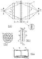
- the drawings illustrate an imaging system 11 ( Figure 1) forming a pseudoscopic image 12 of an object 13.
- the image 12 is in focus throughout an extended depth of field and is in direct 1:1 correlation with the object 13.
- the system 11 comprises an input relay lens array 14 (see also Figure 2 where the array is seen to be a circular array of circular lenses 14a of millimetric diameter), a double integral microlens screen 15 having a median plane on to which the input lens array 14 images the object 13 as illustrated in the scaled-up fragment in Figure 1, and, on the opposite side of the screen 15 and at the same distance D therefrom as the input array 14, an output lens array 16 similar to the input relay lens array 14.
- the relay lens array lenses are substantially larger than the lenslets of the microlens screen, which are of micrometric dimensions.
- microlens screen 15 of the invention is shown in larger-scale cross-section in Figure 3.
- the screen 15 comprises two similar contiguous screens 15b, 15c each comprising double convex microlenses each having a thickness equal to its focal length f. As depicted within the box B this forms an array of micro field lens systems, which image the aperture A 1 on to the aperture A 2 on the opposite face. This reduces vignetting and cross-talk between adjacent entrance and exit lenses of the relay arrays 14, 16.
- the screen translates all impinging ray directions to transmitted ray directions which subtend the same angle to the screen. This not only images the aperture of the input relay lens on to the aperture of the output relay lens but also ensures complete angular parity between rays emanating from the input relay lenses and rays transmitted on to the output relay lenses, which ensures that object and image conjugates formed by the input lens array so removing any lens distortion from the transmitted 1:1 scale image and reducing chromatic and spherical aberration.
- An instrument embodying the image system 11 may have fixed components for example in a dedicated system where the object region is fixed, or may be adjustable so that the conjugate plane of the principal plane of interest in the object scene with respect to the input relay lens array 14 is adjustable to coincide with the median plane of the screen 15. As illustrated in Figure 4, this can be effected by an oppositely threaded lead screw device 51.
- the transmission screen of the invention can be used in conjunction with a photographic plate/film or other surface sensitive to the transmitted radiation which is overlaid with an array of micro spherical or micro cylindrical lenses or an opaque barrier perforated with small apertures in a uniform matrix pattern or a barrier with narrow transparent slits.
- the optical transmission screen can be reduced to a single row of adjacent double lenses which increases the sharpness of the recorded image in the vertical non-parallax axis.
- the system is capable of recording in 1:1 scale in real-time, requiring only a single exposure and in one stage directly produces a 3-D image which can be viewed in its orthoscopic form.
- the focal lengths of each double array can be the same, but by appropriate choice of microlens focal length combinations, magnification in the Z direction can be controlled independently of the X and Y unit magnification.
- the optical elements which comprise the invention is capable of receiving all incoming radiation emanating from object points in the scene and to transmit these ray bundles to an equal but opposite conjugate location in true scale without lens or perspective distortion irresepective of object distance and in full natural colour.
- the system can be made wavelength selective by appropriate selection of material and means.
Landscapes
- Physics & Mathematics (AREA)
- General Physics & Mathematics (AREA)
- Optics & Photonics (AREA)
- Engineering & Computer Science (AREA)
- Multimedia (AREA)
- Signal Processing (AREA)
- Vehicle Body Suspensions (AREA)
- Eye Examination Apparatus (AREA)
- Iron Core Of Rotating Electric Machines (AREA)
- Testing, Inspecting, Measuring Of Stereoscopic Televisions And Televisions (AREA)
- Optical Elements Other Than Lenses (AREA)
- Lenses (AREA)
- Glass Compositions (AREA)
- Studio Devices (AREA)
Claims (3)
- Abbildungssystem zum Erzeugen eines pseudoskopischen Bildes einer Objektszene in Fokus über eine erweiterte Tiefenschärfe mit einem Eingangsrelaislinsenfeld (14), einer doppelten integralen Mikrolinsenplatte (15), mit einer Mittenebene (15a), auf die das Eingangsrelaislisenfeld (14) die Objektszene (13) abbildet und mit einem auf der entgegengesetzten Seite der Platte (15) mit dem gleichen Abstand wie das Eingangsfeld (14) zu ihr angeordneten Ausgangsrelaislinsenfeld (16), da dem Eingangsrelaislinsenfeld (14) entspricht, dadurch gekennzeichnet, daß die doppelte integrale Mikrolinsenplatte (15) zwei gleiche angrenzende Mikrolinsenplatten (15b,15c) umfaßt, die jeweils doppelte konvexe Mikrolinsen aufweisen, wobei jede eine Dicke gleich ihrer Brennweite hat und die optisch so zueinander gekoppelt sind, daß jedes Linsenelement einer der zwei Platten (15b,15c) dem entsprechenden Linsenelement der anderen gegenübersteht.
- Abbildungssystem nach Anspruch 1, bei dem die Relaislinsen (14a) wesentlich größer als die Mikrolinsen der Platte (15) sind.
- Instrument mit einem Abbildungssystem nach Anspruch 1 oder Anspruch 2, wobei das Eingangs- und Ausgangsrelaislinsenfeld (14,16) zur gleichen und gegenüberliegenden Einstellung in bezug auf die doppelte integrale Mikrolinsenplatte (15) angeordnet sind und entsprechende Mittel (51) aufweisen.
Applications Claiming Priority (3)
| Application Number | Priority Date | Filing Date | Title |
|---|---|---|---|
| GB9207140 | 1992-04-01 | ||
| GB929207140A GB9207140D0 (en) | 1992-04-01 | 1992-04-01 | Optical transmission screen |
| PCT/GB1993/000682 WO1993020473A1 (en) | 1992-04-01 | 1993-04-01 | Imaging system |
Publications (2)
| Publication Number | Publication Date |
|---|---|
| EP0634024A1 EP0634024A1 (de) | 1995-01-18 |
| EP0634024B1 true EP0634024B1 (de) | 1997-07-09 |
Family
ID=10713261
Family Applications (1)
| Application Number | Title | Priority Date | Filing Date |
|---|---|---|---|
| EP93906772A Expired - Lifetime EP0634024B1 (de) | 1992-04-01 | 1993-04-01 | Abbildendes system |
Country Status (8)
| Country | Link |
|---|---|
| US (1) | US5615048A (de) |
| EP (1) | EP0634024B1 (de) |
| JP (1) | JP3253301B2 (de) |
| AT (1) | ATE155252T1 (de) |
| AU (1) | AU3766093A (de) |
| DE (1) | DE69312062T2 (de) |
| GB (1) | GB9207140D0 (de) |
| WO (1) | WO1993020473A1 (de) |
Families Citing this family (25)
| Publication number | Priority date | Publication date | Assignee | Title |
|---|---|---|---|---|
| US5650876A (en) * | 1993-03-25 | 1997-07-22 | De Montfort University | Lens system with intermediate optical transmission microlens screen |
| JPH10504403A (ja) * | 1994-06-04 | 1998-04-28 | デ モントフォート ユニヴァーシティ | 可視像を作ること |
| US5619245A (en) * | 1994-07-29 | 1997-04-08 | Eastman Kodak Company | Multi-beam optical system using lenslet arrays in laser multi-beam printers and recorders |
| CN1073781C (zh) * | 1996-01-18 | 2001-10-24 | 余桂丰 | 立体电视摄像与播放接收系统 |
| US5880887A (en) * | 1996-08-16 | 1999-03-09 | Dai Nippon Printing Co., Ltd. | Lenticular lens sheet, display front plate and transmission type projection screen |
| US6115181A (en) * | 1996-11-22 | 2000-09-05 | 3M Innovative Properties Company | Variable beam splitter having opposed alternating convex and concave lens structures |
| US5822125A (en) * | 1996-12-20 | 1998-10-13 | Eastman Kodak Company | Lenslet array system |
| GB9702006D0 (en) * | 1997-01-31 | 1997-03-19 | Univ Montfort | Lens arrangements |
| JP3938253B2 (ja) | 1997-12-26 | 2007-06-27 | 日本板硝子株式会社 | 樹脂正立等倍レンズアレイおよびその製造方法 |
| JP3509534B2 (ja) * | 1998-03-09 | 2004-03-22 | 富士通株式会社 | 光学装置 |
| DE19936230C2 (de) * | 1999-08-05 | 2001-07-12 | Lissotschenko Vitalij | Abbildungsvorrichtung |
| US6377403B1 (en) * | 2000-09-07 | 2002-04-23 | David C. Smith | Short pulse laser protection fly's eye lens |
| US20040046899A1 (en) * | 2002-09-05 | 2004-03-11 | Bonnett Craig Eugene | Vehicle interior projection entertainment system |
| US7319561B2 (en) * | 2004-12-27 | 2008-01-15 | Nippon Sheet Glass Company, Limited | Stereoimage formation apparatus and stereoimage display unit |
| NL1032066C2 (nl) * | 2006-06-27 | 2008-01-02 | Univ Delft Tech | Werkwijze en inrichting voor het vormen van een afbeelding. |
| DE102010012467A1 (de) * | 2010-03-24 | 2011-09-29 | Limo Patentverwaltung Gmbh & Co. Kg | Vorrichtung zur Abbildung einer linienförmigen Lichtverteilung, Laservorrichtung mit einer derartigen Vorrichtung sowie Verfahren zur Herstellung einer derartigen Vorrichtung |
| KR101842421B1 (ko) * | 2010-03-24 | 2018-05-14 | 리모 게엠베하 | 레이저 광선 제공 장치 및 선형 배광 재생 장치 |
| US9423533B2 (en) * | 2010-04-26 | 2016-08-23 | Guardian Industries Corp. | Patterned glass cylindrical lens arrays for concentrated photovoltaic systems, and/or methods of making the same |
| US9151879B2 (en) | 2010-04-26 | 2015-10-06 | Guardian Industries Corp. | Multi-functional photovoltaic skylight and/or methods of making the same |
| US8609455B2 (en) * | 2010-04-26 | 2013-12-17 | Guardian Industries Corp. | Patterned glass cylindrical lens arrays for concentrated photovoltaic systems, and/or methods of making the same |
| DE102011000863A1 (de) | 2011-02-22 | 2012-08-23 | Sick Ag | Optoelektronischer Sensor und Verfahren zur Erfassung von Objekten |
| TWI467226B (zh) | 2011-11-15 | 2015-01-01 | Ind Tech Res Inst | 相位物體顯微系統 |
| US9881529B2 (en) * | 2015-06-12 | 2018-01-30 | Innolux Corporation | Display device and operating method thereof |
| WO2018026851A1 (en) * | 2016-08-02 | 2018-02-08 | Valve Corporation | Mitigation of screen door effect in head-mounted displays |
| CN113179360B (zh) * | 2021-04-26 | 2022-04-08 | 中国科学院长春光学精密机械与物理研究所 | 密集方位采样分块式平面光电成像系统 |
Family Cites Families (4)
| Publication number | Priority date | Publication date | Assignee | Title |
|---|---|---|---|---|
| FR2520518A1 (fr) * | 1982-01-22 | 1983-07-29 | Centre Nat Rech Scient | Appareil optique et procede pour l'enregistrement ou la visualisation instantanee d'images agrandies et stereoscopiques d'objets |
| GB8528286D0 (en) * | 1985-11-16 | 1985-12-18 | Univ Sheffield | Imaging system |
| GB9002327D0 (en) * | 1990-02-02 | 1990-04-04 | Univ Sheffield | Optical elements |
| GB2251754A (en) * | 1990-11-08 | 1992-07-15 | British Telecomm | Three dimensional imaging system |
-
1992
- 1992-04-01 GB GB929207140A patent/GB9207140D0/en active Pending
-
1993
- 1993-04-01 US US08/313,234 patent/US5615048A/en not_active Expired - Fee Related
- 1993-04-01 AU AU37660/93A patent/AU3766093A/en not_active Abandoned
- 1993-04-01 AT AT93906772T patent/ATE155252T1/de not_active IP Right Cessation
- 1993-04-01 EP EP93906772A patent/EP0634024B1/de not_active Expired - Lifetime
- 1993-04-01 DE DE69312062T patent/DE69312062T2/de not_active Expired - Fee Related
- 1993-04-01 JP JP51724493A patent/JP3253301B2/ja not_active Expired - Fee Related
- 1993-04-01 WO PCT/GB1993/000682 patent/WO1993020473A1/en not_active Ceased
Also Published As
| Publication number | Publication date |
|---|---|
| GB9207140D0 (en) | 1992-05-13 |
| JP3253301B2 (ja) | 2002-02-04 |
| EP0634024A1 (de) | 1995-01-18 |
| JPH07508838A (ja) | 1995-09-28 |
| WO1993020473A1 (en) | 1993-10-14 |
| DE69312062D1 (de) | 1997-08-14 |
| DE69312062T2 (de) | 1998-02-05 |
| ATE155252T1 (de) | 1997-07-15 |
| US5615048A (en) | 1997-03-25 |
| AU3766093A (en) | 1993-11-08 |
Similar Documents
| Publication | Publication Date | Title |
|---|---|---|
| EP0634024B1 (de) | Abbildendes system | |
| US7009652B1 (en) | Image input apparatus | |
| US6097541A (en) | Lens arrangements | |
| US5299275A (en) | Optical fiber filter for reducing artifacts in imaging apparatus | |
| US5650876A (en) | Lens system with intermediate optical transmission microlens screen | |
| US8619177B2 (en) | Digital imaging system, plenoptic optical device and image data processing method | |
| DE69837510T2 (de) | Optische vorrichtung, die eine virtuell abgebildete phasenmatrix zur herstellung von chromatischer dispersion verwendet | |
| US6021241A (en) | Systems and methods for using diffraction patterns to determine radiation intensity values for areas between and along adjacent sensors of compound sensor arrays | |
| GB2278222A (en) | Spatial light modulator | |
| GB2284273A (en) | Optical beam splitter and electronic high speed camera incorporating it | |
| JPH11305164A (ja) | 立体画像装置 | |
| US6233035B1 (en) | Image recording apparatus and image reproducing apparatus | |
| EP0704131B1 (de) | Bilderzeugungssystem | |
| CA1336655C (en) | Imaging system | |
| US5283691A (en) | Solid state imaging apparatus | |
| US5321251A (en) | Angled optical fiber filter for reducing artifacts in imaging apparatus | |
| JP3682834B2 (ja) | 波長可変干渉フィルタを用いた光学装置 | |
| JP2019082412A (ja) | 撮像装置 | |
| JP3836550B2 (ja) | 立体撮像装置および立体表示装置 | |
| US5420718A (en) | Optical image system with improved resolution | |
| WO2022163306A1 (ja) | 撮像装置、および撮像方法 | |
| US12101537B2 (en) | Image sensor apparatus of a camera for detecting light | |
| US5629803A (en) | System for a direct image transmission by spectral coding | |
| JPS58100570A (ja) | 固体素子によるラインスキヤナの多素子化方式 | |
| JPS59108479A (ja) | 撮像装置 |
Legal Events
| Date | Code | Title | Description |
|---|---|---|---|
| PUAI | Public reference made under article 153(3) epc to a published international application that has entered the european phase |
Free format text: ORIGINAL CODE: 0009012 |
|
| 17P | Request for examination filed |
Effective date: 19941024 |
|
| AK | Designated contracting states |
Kind code of ref document: A1 Designated state(s): AT BE CH DE DK ES FR GB GR IE IT LI LU MC NL PT SE |
|
| 17Q | First examination report despatched |
Effective date: 19960205 |
|
| GRAG | Despatch of communication of intention to grant |
Free format text: ORIGINAL CODE: EPIDOS AGRA |
|
| GRAH | Despatch of communication of intention to grant a patent |
Free format text: ORIGINAL CODE: EPIDOS IGRA |
|
| GRAH | Despatch of communication of intention to grant a patent |
Free format text: ORIGINAL CODE: EPIDOS IGRA |
|
| GRAA | (expected) grant |
Free format text: ORIGINAL CODE: 0009210 |
|
| AK | Designated contracting states |
Kind code of ref document: B1 Designated state(s): AT BE CH DE DK ES FR GB GR IE IT LI LU MC NL PT SE |
|
| PG25 | Lapsed in a contracting state [announced via postgrant information from national office to epo] |
Ref country code: NL Free format text: LAPSE BECAUSE OF FAILURE TO SUBMIT A TRANSLATION OF THE DESCRIPTION OR TO PAY THE FEE WITHIN THE PRESCRIBED TIME-LIMIT Effective date: 19970709 Ref country code: IT Free format text: LAPSE BECAUSE OF FAILURE TO SUBMIT A TRANSLATION OF THE DESCRIPTION OR TO PAY THE FEE WITHIN THE PRESCRIBED TIME-LIMIT;WARNING: LAPSES OF ITALIAN PATENTS WITH EFFECTIVE DATE BEFORE 2007 MAY HAVE OCCURRED AT ANY TIME BEFORE 2007. THE CORRECT EFFECTIVE DATE MAY BE DIFFERENT FROM THE ONE RECORDED. Effective date: 19970709 Ref country code: GR Free format text: LAPSE BECAUSE OF FAILURE TO SUBMIT A TRANSLATION OF THE DESCRIPTION OR TO PAY THE FEE WITHIN THE PRESCRIBED TIME-LIMIT Effective date: 19970709 Ref country code: ES Free format text: THE PATENT HAS BEEN ANNULLED BY A DECISION OF A NATIONAL AUTHORITY Effective date: 19970709 Ref country code: DK Effective date: 19970709 Ref country code: BE Effective date: 19970709 Ref country code: AT Effective date: 19970709 |
|
| REF | Corresponds to: |
Ref document number: 155252 Country of ref document: AT Date of ref document: 19970715 Kind code of ref document: T |
|
| REG | Reference to a national code |
Ref country code: CH Ref legal event code: EP |
|
| REF | Corresponds to: |
Ref document number: 69312062 Country of ref document: DE Date of ref document: 19970814 |
|
| PG25 | Lapsed in a contracting state [announced via postgrant information from national office to epo] |
Ref country code: SE Effective date: 19971009 |
|
| PG25 | Lapsed in a contracting state [announced via postgrant information from national office to epo] |
Ref country code: PT Effective date: 19971017 |
|
| ET | Fr: translation filed | ||
| NLV1 | Nl: lapsed or annulled due to failure to fulfill the requirements of art. 29p and 29m of the patents act | ||
| REG | Reference to a national code |
Ref country code: CH Ref legal event code: NV Representative=s name: ROTTMANN, ZIMMERMANN + PARTNER AG |
|
| PG25 | Lapsed in a contracting state [announced via postgrant information from national office to epo] |
Ref country code: LU Free format text: LAPSE BECAUSE OF NON-PAYMENT OF DUE FEES Effective date: 19980401 Ref country code: IE Free format text: LAPSE BECAUSE OF NON-PAYMENT OF DUE FEES Effective date: 19980401 |
|
| PLBE | No opposition filed within time limit |
Free format text: ORIGINAL CODE: 0009261 |
|
| STAA | Information on the status of an ep patent application or granted ep patent |
Free format text: STATUS: NO OPPOSITION FILED WITHIN TIME LIMIT |
|
| 26N | No opposition filed | ||
| PG25 | Lapsed in a contracting state [announced via postgrant information from national office to epo] |
Ref country code: MC Free format text: LAPSE BECAUSE OF NON-PAYMENT OF DUE FEES Effective date: 19981031 |
|
| REG | Reference to a national code |
Ref country code: GB Ref legal event code: IF02 |
|
| PGFP | Annual fee paid to national office [announced via postgrant information from national office to epo] |
Ref country code: FR Payment date: 20040311 Year of fee payment: 12 |
|
| PGFP | Annual fee paid to national office [announced via postgrant information from national office to epo] |
Ref country code: CH Payment date: 20040312 Year of fee payment: 12 |
|
| PGFP | Annual fee paid to national office [announced via postgrant information from national office to epo] |
Ref country code: GB Payment date: 20040316 Year of fee payment: 12 |
|
| PGFP | Annual fee paid to national office [announced via postgrant information from national office to epo] |
Ref country code: DE Payment date: 20040330 Year of fee payment: 12 |
|
| PG25 | Lapsed in a contracting state [announced via postgrant information from national office to epo] |
Ref country code: GB Free format text: LAPSE BECAUSE OF NON-PAYMENT OF DUE FEES Effective date: 20050401 |
|
| PG25 | Lapsed in a contracting state [announced via postgrant information from national office to epo] |
Ref country code: LI Free format text: LAPSE BECAUSE OF NON-PAYMENT OF DUE FEES Effective date: 20050430 Ref country code: CH Free format text: LAPSE BECAUSE OF NON-PAYMENT OF DUE FEES Effective date: 20050430 |
|
| PG25 | Lapsed in a contracting state [announced via postgrant information from national office to epo] |
Ref country code: DE Free format text: LAPSE BECAUSE OF NON-PAYMENT OF DUE FEES Effective date: 20051101 |
|
| REG | Reference to a national code |
Ref country code: CH Ref legal event code: PL |
|
| GBPC | Gb: european patent ceased through non-payment of renewal fee |
Effective date: 20050401 |
|
| PG25 | Lapsed in a contracting state [announced via postgrant information from national office to epo] |
Ref country code: FR Free format text: LAPSE BECAUSE OF NON-PAYMENT OF DUE FEES Effective date: 20051230 |
|
| REG | Reference to a national code |
Ref country code: FR Ref legal event code: ST Effective date: 20051230 |