EP0631850B1 - Vorrichtung zum Bearbeiten - Google Patents
Vorrichtung zum Bearbeiten Download PDFInfo
- Publication number
- EP0631850B1 EP0631850B1 EP94102999A EP94102999A EP0631850B1 EP 0631850 B1 EP0631850 B1 EP 0631850B1 EP 94102999 A EP94102999 A EP 94102999A EP 94102999 A EP94102999 A EP 94102999A EP 0631850 B1 EP0631850 B1 EP 0631850B1
- Authority
- EP
- European Patent Office
- Prior art keywords
- compression
- jaws
- rollers
- press
- sleeve
- Prior art date
- Legal status (The legal status is an assumption and is not a legal conclusion. Google has not performed a legal analysis and makes no representation as to the accuracy of the status listed.)
- Expired - Lifetime
Links
Images


Classifications
-
- B—PERFORMING OPERATIONS; TRANSPORTING
- B26—HAND CUTTING TOOLS; CUTTING; SEVERING
- B26B—HAND-HELD CUTTING TOOLS NOT OTHERWISE PROVIDED FOR
- B26B17/00—Hand cutting tools, i.e. with the cutting action actuated by muscle power with two jaws which come into abutting contact
- B26B17/02—Hand cutting tools, i.e. with the cutting action actuated by muscle power with two jaws which come into abutting contact with jaws operated indirectly by the handles, e.g. through cams or toggle levers
-
- B—PERFORMING OPERATIONS; TRANSPORTING
- B25—HAND TOOLS; PORTABLE POWER-DRIVEN TOOLS; MANIPULATORS
- B25B—TOOLS OR BENCH DEVICES NOT OTHERWISE PROVIDED FOR, FOR FASTENING, CONNECTING, DISENGAGING, OR HOLDING
- B25B27/00—Hand tools, specially adapted for fitting together or separating parts or objects whether or not involving some deformation, not otherwise provided for
- B25B27/14—Hand tools, specially adapted for fitting together or separating parts or objects whether or not involving some deformation, not otherwise provided for for assembling objects other than by press fit or detaching same
- B25B27/146—Clip clamping hand tools
-
- B—PERFORMING OPERATIONS; TRANSPORTING
- B25—HAND TOOLS; PORTABLE POWER-DRIVEN TOOLS; MANIPULATORS
- B25B—TOOLS OR BENCH DEVICES NOT OTHERWISE PROVIDED FOR, FOR FASTENING, CONNECTING, DISENGAGING, OR HOLDING
- B25B7/00—Pliers; Other hand-held gripping tools with jaws on pivoted limbs; Details applicable generally to pivoted-limb hand tools
- B25B7/12—Pliers; Other hand-held gripping tools with jaws on pivoted limbs; Details applicable generally to pivoted-limb hand tools involving special transmission means between the handles and the jaws, e.g. toggle levers, gears
- B25B7/126—Pliers; Other hand-held gripping tools with jaws on pivoted limbs; Details applicable generally to pivoted-limb hand tools involving special transmission means between the handles and the jaws, e.g. toggle levers, gears with fluid drive
Definitions
- the invention relates to pressing tongs, For deformable sleeves, preferably for composite pipes or lines according to the preamble of claim 1, as is known from US-A-5 125 124.
- Generic Crimping pliers for pressing crimp sleeves for pipe or Hose connections work uniformly according to a principle in which the positive spreading of actuating legs that force flow to the press jaws cause two fulcrums to occur. In doing so Spreading rollers along control cams or control links towards the pivot points. For this purpose, the Control curves or control scenes in the direction of the Pivots tapered.
- the known generic Crimping pliers with such large dimensions Drives should be provided that an operator either must be exceptionally vigorous to be a longer term Make handling of the known devices can, or must be replaced after a short time.
- the known devices are so heavy that they are unfavorable Positions, for example in pipe shafts or The like is extremely difficult or difficult to handle are.
- the advantages to be achieved by the present invention are based on the fact that the power transmission device, for example in the form of an electric motor with a screw drive, exerts a tractive force that closes the Processing elements, or the cutting press jaws is used.
- This traction is controlled by a Press jaw actuator progressive, i.e. With increasing power arm, on the actuator of the Processing organs and thus on the Press jaws transferred, the load arm remains essentially unchanged.
- the two actuators have for the press jaws according to the invention each on a control curve or backdrop on which the at least a roller or the spreading roller is guided. It points the control curve or backdrop in the open state of the Press jaws to the line of the closed Condition of the press jaws adjacent jaw halves a smaller angle on than in the closed state.
- the spreading rollers pulled back by a tensile force be, with the spreading rollers along the control curve or control curves run on which the spreading rollers are supported, the spreading rollers due to the in Direction of the incoming control curve or control curves or -scapes of the actuation device or devices, for example, operating arms, spread apart, which increases the strength with a progressive arm the press jaws is transferred to the Press jaws moved towards each other.
- the power arm increases and the greatest power or largest power arm is available when on the press jaws the greatest force is needed, though Power transmission or generation device relatively low is dimensioned.
- control curve or link has an area on who in the closed state the press jaws an essentially ineffective movement, in particular allows the idler rollers or rollers to run freely.
- a sensing device on the invention Device be arranged, the ineffective movement detected and a display or a limit switch can cause.
- a limit switch could only made by querying a preset force be, so that the limit switch no information about it could convey whether a pressing process was successful had been carried out and ended. That way carried out pressing processes with the known devices, that left no tight or watertight connection. The result is leaky connections and extensive Reworking.
- An advantageous embodiment is one Malfunction no longer possible because of the Press jaws only in closed state, namely when the spreading rollers have changed into an ineffective movement, in the Switch state, so that the sensing device appeals and a final display, for example in the form of a optical or acoustic signal, and optionally one Limit switch initiated.
- the invention Device additionally have an overload clutch, the an emergency or limit stop causes damage the pressing tongs according to the invention avoid.
- the pressing tongs according to the invention advantageously have just a fulcrum for the Press jaws on what according to the present invention is sufficient because the leverage is progressive and an excessive load on the bearing that is at the pivot point is arranged, does not occur.
- the State of the art two pivot points for the jaws used to be especially given the increasingly deteriorating during the pressing process Ratio of power arm to load arm the necessary To apply or be able to absorb forces.
- This known design not only led to the fact that Actuators for the Press jaws themselves are very heavy have, but also that the Press jaws had to be replaced in total if processed or pressed, for example, compression sleeves of a different size should be, for example, composite pipes, in particular Plastic composite pipes of different diameters connect with each other.
- the inserts on corresponding sizes of press sleeves are adjusted so that by simply replacing the Inserts the fixed jaws any sleeves to be pressed can be adapted.
- the actuating devices or Actuating leg on the processing organs opposite side one or one recess on to the drive rod or the drive shaft record when the actuating legs in their im essential or completely closed position. This allows the opening angle for the Enlarge processing elements.
- one of the actuating legs Have recesses to complement each other accordingly trained sections of the opposite To be able to accommodate the actuating arm.
- This can the opening angle for the press jaws by itself or in Combination with the recesses for the drive rod or wave are enlarged. In any case, remains sufficient space to hold the rollers or spreading rollers enable yourself to face the control curves or backdrops and support each other.
- the distance between the Actuating legs in their closed state like this be chosen that the spreader or each other adjacent spreading rollers make contact with them in have control curve sections assigned to this position.
- the distance can be a spreader roll diameter entirely significantly exceed the opening angle for the Press jaws to increase additionally.
- the inner contours that are suitable for pressing the press jaws have a particularly advantageous manner Sections on to the wall of a compression sleeve in extremely radially inward and / or controlled manner to be able to deflect radially outwards. For this result the different sections of the press contours summed up one Length that is at least substantially the outer circumference of the Press sleeve corresponds.
- a press sleeve, a support sleeve and a tube can on the inner circumference of the press jaws, i.e. on the Press contours can also be provided in alternative areas. These avoidance areas can expediently on the End areas of the respective half profiles of the respective Press jaws can be provided.
- are bigger Fearing manufacturing tolerances can be corresponding Evasion areas also in the course of the half-profiles of the Press jaws can be provided, for example on the Quarter circumference of the closed press profile closed press jaws.
- the press sleeve can also be part of the invention be considered.
- the inner contour of the press jaws can also be designed in this way be like this for that by the notifier in principle known connection technology, which is called "Fripexan” is already used.
- a sliding sleeve is used with a internal chamfer to the fitting body or base body over a certain distance, e.g. about 5cm, over the right-angled pipe end is pushed on.
- the end of the pipe is pushed onto the expander part until it stops pushed on in principle known expansion tool, and by operating a hand lever of the same, the pipe expanded.
- a support sleeve of a base body is in the widened pipe end pushed. It usually remains a distance of a few millimeters, for example 3mm to 4mm, between the pipe end and the fitting collar of the Fitting body.
- the tube diameter or basic body Matching bets are placed in the appropriate configured press jaws of the device according to the invention used, or the device according to the invention appropriately designed press jaws.
- the sliding sleeve with the assembly tool up to the fitting collar postponed and the connection process is at least essentially completed.
- the process of postponing takes place in such a way that the support sleeve with the previously widened, pushed tube to the corresponding Contours inserted in and / or on the press jaws or is scheduled.
- control curves or -screens that are the ineffective or the cutting or non-pressing movement or free running of the rollers or allow spreading rollers in the closed state of the Processing elements or press jaws with a distance of approximately two roll or spreading roll diameters arranged parallel to each other.
- Fig. 1 is a pressing tongs designed according to the invention 10 shown.
- the pressing tongs 10 have a lower grip section 28 in which a relatively small dimension Electric motor, a control board for the electric motor and if necessary, further electrical or mechanical parts, if necessary for a sensing device for limit switching, a planetary gear and the like housed more can be a controlled power source for a pressing process to provide.
- the electric motor can via a threaded rod, for example with one for one Saw thread designed for tractive force, on a nut 26, 26a that engage with a push rod 30 is connected to this according to the direction of rotation of the Electric motor or the planetary gear train or To move the thrust.
- two rollers 18, 18 'are mounted, which with the push or pull rod 30 moves forward or backward can be.
- the front part of the pressing tongs designed according to the invention 10 has two press jaws 12, which have a common Pivot 16 are pivotable.
- the press jaws 12 are moved towards each other via the actuating legs 32.
- the spreading roller 18 symbolizes the open state of the press jaws 12 by the angled press jaw 12a is indicated.
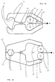
- the control curves 17, 22, 24 consist of a first section 17, in which the spreading rollers 18, 18 'in a rest position be included. In the pulling direction of the spreading rollers 18, 18 'close the inclined cam sections 22, via which the progressive power arm realizes becomes. Regarding sections 22, it should be noted that that these are not necessarily at an even angle must run obliquely. It is only important that the sections 22 have an increasing gradient at least in some areas, which is also characterized by a hyperbolic, parabolic, partially circular or other design realized can be. The only important thing is that the actuating legs when the spreading rollers 18, 18 'are pulled back be so that the press jaws 12 towards each other be moved.
- section 24 which represents a section in which none due to the pulling force via the spreading rollers 18, 18 ' Force is transmitted to the actuating leg, whereby the spread remains constant when the spreading rollers 18, 18 'run along these sections 24.
- the sections 24 of the two control curves or -screens run parallel to each other when the press jaws 12 in are in their closed state.
- the sections run 24 for the end display or limit switch essentially with a distance of two spreading roller diameters parallel to each other.
- the press jaws 12 have inner sections 14, which can be provided to receive inserts (not shown), adapted to different press sleeve sizes are. Such inserts can be used, for example, with Allen screws or the like attached to the press jaws 12 become.
- FIG. 2a the principle of operation is that shown in Fig. 1 preferred embodiment of the pressing tongs 10 according to reproduced the present invention for clarification. Areas or parts with the same reference numerals as shown in Fig. 1 are identical or at least functionally the same as that shown in Fig. 1 Areas or parts.
- the direction of action Z of the tensile force is indicated in FIG. 2a been.
- the press jaws 12 and the actuating legs 32 are about a common pivot point 16, for example in Form of a swivel joint rotated or swiveled.
- pivot point 16 instead of one pivot point 16, two pivot points can also be used are used, the arranged in the pivot points Swivel joints supported against each other via a support structure could be.
- the closing of the press jaws 12 can by means of a spring device tensioned during the pressing process or be made by a reversing device.
- the press jaw halves are in the state shown in FIG. 2b 12 or their half-cut surfaces parallel to each other tight and thus form a closed mold around the pressed part or the compression sleeve.
- 3 is a preferred embodiment according to the Present invention shown, also as Crimping pliers can be used.
- the control curves or control links are however, trained longer than this for the full Opening of the press jaws 12 would be required. I.e. the Distance between the end position of the roller 18 and the section the control curve or link on which the rollers 18, 18 'a force exerted for the first time is greater than this for a sufficiently wide opening in which one Press sleeve 50 are inserted between the press jaws 12 can, would be required.
- This essentially leads to two effects, namely one that the press jaws 12 open further, and on the other hand that the Actuator leg 32 before the rollers 18, 18 'a force exercise on these are already relatively closed.
- the actuating legs 32 can be in a (here housing device (not shown) are drawn in, before powers are exerted. Through this safety measures can prevent accidents e.g. squeezing fingers etc.
- the ends of the actuating legs 32 may be designed that one end of an operating leg 32 the other End of an actuation leg as required can record.
- one of the Actuating leg 32 with a recess or Recesses 36 may be provided, to which corresponding ones Sections on the opposite actuation leg 32 can fit.
- the two Press jaws 12 may be provided with a bolt 16 for different sizes of compression sleeves 50 different pressing head 40 can be provided can. Since the individual crimping pliers heads 40 are relatively light are, the light pressing tongs or their motor skills and Drive technology and a variety of such Crimping heads 40 in a smaller case to the construction site get picked up.
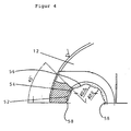
- the press jaws 12 At the front end of the press jaws 12 are different Contours provided for controlled deformation provide a press sleeve 50. So there are at the two Press jaws 12 areas 52 are provided, the different Have sections 54, 56.
- the sections 54, 56 can for example consist of two essentially together adjacent areas with different radii consist.
- the different sections 54, 56 result essentially the entire scope of a Press sleeve 50 before the pressing process.
- the respective press jaws 12 Dodge areas 58 are provided to accommodate material can, for example, with a perfect pressing. due to dimensional tolerances of compression in the material the press sleeve 50 was lead.
- each Press jaws 12 has the following background: With one Press sleeve 50, which is shown only schematically in FIG. 3 as a semicircle is shown for the purpose of connecting one Rohres with other known from the connection technology Parts, for example pipe sockets, intermediate pieces and the like more, at least certain sections on the press sleeve 50 be plastically deformed.
- the relevant plastically deflected Cutouts over which, for example, a composite pipe with Metal and plastic with one arranged in the tube Support sleeve can be connected the sections several plastic, radially inwards towards the assigned support sleeve deflected, first sections and several unchanged and / or radially outward from the assigned support sleeve deflected away second Can have sections.
- the first and the second sections of the plastically deformed Press sleeve give a length over the circumference of the press sleeve the circumference of the undeformed compression sleeve 50 in essential, advantageously corresponds exactly.
- avoidance areas 58 also uneven, possibly during the pressing process occurring material migration of the material of the Support sleeve 50 compensate for this material migration can be accommodated by the escape areas 58.
- the end of the press jaws 12 is in detail shown.
- the material of a (not shown) Press sleeve 50 can move in during the pressing process Spread recesses 54 while it is through the Profilings 56 is deflected radially inwards. Due to irregularities during the pressing process and due to manufacturing tolerances Material migration of the material of the press sleeve can are taken up by the evasive areas 58 which the respective end sections of the profiles 52 of the opposing press jaws 12 are formed. Dimensions are shown by way of example from FIG. 4.
Landscapes
- Engineering & Computer Science (AREA)
- Mechanical Engineering (AREA)
- Life Sciences & Earth Sciences (AREA)
- Forests & Forestry (AREA)
- Press Drives And Press Lines (AREA)
- Electrical Discharge Machining, Electrochemical Machining, And Combined Machining (AREA)
- Scissors And Nippers (AREA)
- Input Circuits Of Receivers And Coupling Of Receivers And Audio Equipment (AREA)
- Diaphragms For Electromechanical Transducers (AREA)
- Ticket-Dispensing Machines (AREA)
Description
- Fig. 1
- eine erfindungsgemäße Preßzange, in einer Prinzipdarstellung, in einem teilweisen Längsschnitt,
- Fig. 2a
- eine Prinzipdarstellung der Steuerkurven und der Kraftübertragungsmimik der Ausführungsform gemäß Fig. 1;
- Fig. 2b
- die Prinzipdarstellung gemäß Fig. 2a, wobei die Preßbacken in einem geschlossenen Zustand sind;
- Fig. 3
- eine bevorzugte Ausführungsform der erfindungsgemäßen Preßzange genannt, in einer Prinzipdarstellung in einem Längsschnitt, und
- Fig. 4
- die Ausgestaltung einer Preßbacke in einem teilweisen Längsschnitt.
Claims (10)
- Preßzange für deformierbare Hülsen von Leitungsverbindungen für Sanitär- und Wasserrohre, vorzugsweise Verbundrohre bzw. -leitungen, mit den folgenden Merkmalen:gekennzeichnet durch die folgenden Merkmale:zwei Preßbacken (12),zwei Betätigungseinrichtungen (32), die jeweils eine Steuerkurve bzw. - kulisse (22) umfassen, die jeweils eine der Preßbacken betätigen,jede der Preßbacken ist mit der jeweils ihr zugeordneten Betätigungseinrichtung schwenkbar gelagert,ein Elektromotor, der eine Antriebskraft bereitstellt,eine Kraftübertragungseinrichtung, um die Antriebskraft für die Preßbacken vom Elektromotor über eine Spreizeinrichtung, die zwei Rollen bzw. Spreizrollen hat, auf die Betätigungseinrichtungen zu übertragen,die Rollen bzw. Spreizrollen sind den Steuerkulissen derart zugeordnet, daß bei Bewegung der Spreizeinrichtung die jeweiligen Betätigungseinrichtungen im Sinne eines Schließens der Preßbacken betätigt werden, wobei ein Übertragungsglied (30), insbesondere eine Zugstange oder -welle (30) die Antriebskraft vom Elektromotor auf die Kraftübertragungseinrichtung überträgt,a) die Kraftübertragungseinrichtung wandelt die Antriebskraft in eine Zugkraft (Z), um die Rollen bzw. Spreizrollen (18) der Spreizeinrichtung (22, 32) über das Übertragungsglied (30), das für die Übertragung einer Zugkraft ausgebildet ist, entlang den Steuerkurven bzw. -kulissen (22) zu bewegen, wobei der Kraftarm der Betätigungseinrichtung (32) gegenüber dem Lastarm der Preßbacken (12) zunimmt,b) die Steuerkurven bzw. -kulissen (22) weisen einen Bereich (24) auf, der im geschlossenen Zustand der Preßbacken (12) eine im wesentlichen preßwirkungsfreie Bewegung, insbesondere einen Freilauf, der Rollen bzw. Spreizrollen (18) ermöglicht, der erkennbar ist, um eine Beendigung des Preßvorganges zu ermöglichen,c) die Bereiche (24) der Steuerkurven bzw. -kulissen (22) verlaufen im geschlossenen Zustand der Preßbacken (12) im wesentlichen parallel zueinander.
- Preßzange nach Anspruch 1, dadurch gekennzeichnet, daß eine Fühleinrichtung angeordnet ist, die die im wesentlichen wirkungsfreie Bewegung bzw. den Freilauf fühlt und durch die eine Endanzeige bzw. -abschaltung vornehmbar ist.
- Preßzange nach einem der Ansprüche 1 oder 2, dadurch gekennzeichnet, daß die Betätigungseinrichtungen um einen gemeinsamen Drehpunkt (16) schwenkbar sind oder jede um einen eigenen Drehpunkt schwenkbar ist.
- Preßzange nach einem der Ansprüche 1 bis 3, dadurch gekennzeichnet, daß zwischen der Krafübertragungseinrichtung und dem Elektromotor eine Überlastkupplung angeordnet ist.
- Preßzange nach einem der Ansprüche 1 bis 4, dadurch gekennzeichnet, daß die Betätigungseinrichtungen (32) bzw. Betätigungsschenkel (32) an der zu den Preßbacken (12) gegenüberliegenden Seite eine bzw. jeweils eine Ausnehmung aufweisen, um die Zugstange oder -welle (30) aufzunehmen.
- Preßzange nach einem der Ansprüche 1 bis 5, dadurch gekennzeichnet, daß die Preßbacken (12) an Preßbereichen (52) mit Abschnitten (54, 56) versehen sind, die in bezug auf das Zentrum bzw. den Mittelpunkt der geschlossenen Preßbereiche (52) unterschiedliche Abmessungen bzw. Längen aufweisen, die aufsummiert im wesentlichen dem Umfang bzw. Außenumfang einer zu verpressenden Preßhülse (50) entsprechen.
- Preßzange nach Anspruch 6, dadurch gekennzeichnet, daß die Abschnitte zumindest im wesentlichen durch aneinander angrenzende Teilabschnitte (54, 56) mit mindestens zwei unterschiedlichen Radien ausgebildet sind, die vorzugsweise aufsummiert im wesentlichen dem Umfang bzw. Außenumfang einer zu verpressenden Preßhülse (50) entsprechen.
- Preßzange nach einem der Ansprüche 1 bis 7, dadurch gekennzeichnet, daß die Preßbacken (12) an mindestens einer, vorzugsweise mindestens zwei Stellen einen Ausweichbereich (58) aufweisen, um eine etwa auftretende Massebewegung in dem Material einer Preßhülse (50) insbesondere bei Maßtoleranzen aufzufangen.
- Preßzange nach Anspruch 8, dadurch gekennzeichnet, daß die Ausweichbereiche (58) vorzugsweise an den Endbereichen der jweiligen Preßbacken (12) vorgesehen sind.
- Preßzange nach einem der Ansprüche 1 bis 9, dadurch gekennzeichnet, daß die Preßbacken (12) für das axiale Aufschieben einer Hülse, bspw. einer Schiebe- oder Preßhülse, auf eine Anordnung aus einem Rohr, insbesondere Verbundrohr, und einer darin befindlichen Stützhülse, die bis an einen Bund der Stützhülse in das Rohr eingeschoben ist, ausgebildet sind.
Applications Claiming Priority (2)
| Application Number | Priority Date | Filing Date | Title |
|---|---|---|---|
| DE4321235A DE4321235C2 (de) | 1993-06-25 | 1993-06-25 | Preßzange |
| DE4321235 | 1993-06-25 |
Publications (2)
| Publication Number | Publication Date |
|---|---|
| EP0631850A1 EP0631850A1 (de) | 1995-01-04 |
| EP0631850B1 true EP0631850B1 (de) | 2000-04-26 |
Family
ID=6491267
Family Applications (1)
| Application Number | Title | Priority Date | Filing Date |
|---|---|---|---|
| EP94102999A Expired - Lifetime EP0631850B1 (de) | 1993-06-25 | 1994-02-28 | Vorrichtung zum Bearbeiten |
Country Status (4)
| Country | Link |
|---|---|
| EP (1) | EP0631850B1 (de) |
| AT (1) | ATE192060T1 (de) |
| DE (2) | DE4321235C2 (de) |
| GR (1) | GR3033980T3 (de) |
Families Citing this family (5)
| Publication number | Priority date | Publication date | Assignee | Title |
|---|---|---|---|---|
| DE29604276U1 (de) * | 1996-03-08 | 1996-05-09 | Novopress GmbH Pressen und Presswerkzeuge & Co KG, 41460 Neuss | Prüfgerät |
| EP0882531A3 (de) * | 1997-05-28 | 2002-10-16 | Fränkische Rohrwerke Gebr. Kirchner GmbH & Co. | Bearbeitungsvorrichtung, insbesondere Presszange |
| JP2931299B1 (ja) * | 1998-07-21 | 1999-08-09 | 明邦株式会社 | ホッグリング締結装置 |
| US6662620B1 (en) | 2000-09-12 | 2003-12-16 | Black & Decker Inc. | Steel stud crimper |
| DE10318508B4 (de) * | 2003-02-07 | 2008-02-28 | Gustav Klauke Gmbh | Pressbackenhebelpaar für hydraulische oder elektrische Verpressgeräte |
Citations (1)
| Publication number | Priority date | Publication date | Assignee | Title |
|---|---|---|---|---|
| US2867808A (en) * | 1955-12-12 | 1959-01-13 | Rotor Tool Company | Tool for clinching hog rings |
Family Cites Families (10)
| Publication number | Priority date | Publication date | Assignee | Title |
|---|---|---|---|---|
| US2766631A (en) * | 1950-06-09 | 1956-10-16 | Rotor Tool Company | Power multiplying mechanism for portable hand tools |
| US3269223A (en) * | 1964-11-04 | 1966-08-30 | James A Pawloski | Fluid operated hand tool |
| DE1975194U (de) * | 1964-11-13 | 1967-12-14 | Kipp Maschf Heinrich | Klemmvorrichtung zur montage an einer werkbank. |
| US3630391A (en) * | 1969-01-28 | 1971-12-28 | Gulf & Western Ind Prod Co | Work gripper |
| DE2046561A1 (de) * | 1970-09-22 | 1972-03-16 | Glas, Michael Maurus, 8300 Landshut | Kugelgelagerte Zange |
| GB1456703A (en) * | 1973-03-26 | 1976-11-24 | Dresser Ind | Gripper for pipe handling apparatus machine for spi |
| US3830089A (en) * | 1973-10-01 | 1974-08-20 | Cooper Ind Inc | Ring clinching tool |
| DE3603672A1 (de) * | 1986-02-06 | 1987-08-13 | Dischler Helmut | Schaltbare und selbsttaetig abschaltbare ueberlastkupplung, insbesondere fuer handwerkzeuge |
| US5125324A (en) * | 1988-02-10 | 1992-06-30 | Daia Industry Co. Ltd. | Portable hydraulically operated device incorporating automatic drain valve |
| US5090101A (en) * | 1990-09-18 | 1992-02-25 | Iowa Precision Industries, Inc. | Duct corner installation tool |
-
1993
- 1993-06-25 DE DE4321235A patent/DE4321235C2/de not_active Expired - Fee Related
-
1994
- 1994-02-28 EP EP94102999A patent/EP0631850B1/de not_active Expired - Lifetime
- 1994-02-28 DE DE59409301T patent/DE59409301D1/de not_active Expired - Fee Related
- 1994-02-28 AT AT94102999T patent/ATE192060T1/de not_active IP Right Cessation
-
2000
- 2000-07-19 GR GR20000401665T patent/GR3033980T3/el not_active IP Right Cessation
Patent Citations (1)
| Publication number | Priority date | Publication date | Assignee | Title |
|---|---|---|---|---|
| US2867808A (en) * | 1955-12-12 | 1959-01-13 | Rotor Tool Company | Tool for clinching hog rings |
Also Published As
| Publication number | Publication date |
|---|---|
| GR3033980T3 (en) | 2000-11-30 |
| EP0631850A1 (de) | 1995-01-04 |
| DE4321235A1 (de) | 1995-01-05 |
| DE4321235C2 (de) | 1996-05-30 |
| ATE192060T1 (de) | 2000-05-15 |
| DE59409301D1 (de) | 2000-05-31 |
Similar Documents
| Publication | Publication Date | Title |
|---|---|---|
| DE10101440B4 (de) | Preßzange | |
| EP3687737B1 (de) | Presswerkzeug zum verpressen von fittings zur herstellung von rohrverbindungen | |
| EP0860245B1 (de) | Pressgerät | |
| DE10026829A1 (de) | Vorrichtung zum Festspannen eines Werkstücks mit unebener Oberfläche | |
| EP0824979B1 (de) | Verfahren zum Verbinden von Werkstücken sowie Pressgerät hierfür | |
| EP0627273A2 (de) | Presswerkzeug | |
| EP1629937B1 (de) | Spanndorn mit innenliegenden Spannmitteln | |
| EP1095739B1 (de) | Presswerkzeug und Verfahren zum kaltumformenden Verbinden von Werkstücken | |
| DE102004005014A1 (de) | Elektrische Klemmvorrichtung | |
| DE2617610A1 (de) | Kraftbetaetigtes drehmoment-werkzeug | |
| EP1459825B1 (de) | Trennvorrichtung für Werkstücke, wie Stangen, Bolzen und dergleichen, insbesondere für Gewindestangen | |
| EP0631850A1 (de) | Vorrichtung zum Bearbeiten | |
| DE4321249C2 (de) | Preßzange | |
| EP0155987B1 (de) | Dreh- und Einstellwerkzeug für axialsymmetrische Werkstücke, insbesondere für Spurstangen an Kraftfahrzeugen | |
| DE102009000901A1 (de) | Dreistufige Ventilschaltanordnung | |
| DE19616975B4 (de) | Verfahren zur Prüfung der Preßkraft eines Preßwerkzeuges | |
| DE10019132B4 (de) | Ratschen-Ringschlüssel für Überwurfmuttern an Leitungen | |
| WO2024230999A1 (de) | Presswerkzeug | |
| DE102005046333B3 (de) | Presswerkzeug | |
| DE102005060511A1 (de) | Spannvorrichtung | |
| EP3939746A1 (de) | Pressmaschine mit sicherungselement | |
| EP2902153A1 (de) | Zange | |
| EP4385664A1 (de) | Elektrohandwerkzeug und verfahren zum betreiben eines elektrohandwerkzeugs | |
| DE3930710C2 (de) | ||
| DE3622392C2 (de) |
Legal Events
| Date | Code | Title | Description |
|---|---|---|---|
| PUAI | Public reference made under article 153(3) epc to a published international application that has entered the european phase |
Free format text: ORIGINAL CODE: 0009012 |
|
| AK | Designated contracting states |
Kind code of ref document: A1 Designated state(s): AT BE CH DE FR GR IT LI NL |
|
| 17P | Request for examination filed |
Effective date: 19950104 |
|
| 17Q | First examination report despatched |
Effective date: 19960125 |
|
| GRAG | Despatch of communication of intention to grant |
Free format text: ORIGINAL CODE: EPIDOS AGRA |
|
| GRAG | Despatch of communication of intention to grant |
Free format text: ORIGINAL CODE: EPIDOS AGRA |
|
| GRAH | Despatch of communication of intention to grant a patent |
Free format text: ORIGINAL CODE: EPIDOS IGRA |
|
| GRAH | Despatch of communication of intention to grant a patent |
Free format text: ORIGINAL CODE: EPIDOS IGRA |
|
| GRAA | (expected) grant |
Free format text: ORIGINAL CODE: 0009210 |
|
| ITF | It: translation for a ep patent filed | ||
| AK | Designated contracting states |
Kind code of ref document: B1 Designated state(s): AT BE CH DE FR GR IT LI NL |
|
| REF | Corresponds to: |
Ref document number: 192060 Country of ref document: AT Date of ref document: 20000515 Kind code of ref document: T |
|
| REG | Reference to a national code |
Ref country code: CH Ref legal event code: NV Representative=s name: RIEDERER HASLER & PARTNER PATENTANWAELTE AG Ref country code: CH Ref legal event code: EP |
|
| REF | Corresponds to: |
Ref document number: 59409301 Country of ref document: DE Date of ref document: 20000531 |
|
| ET | Fr: translation filed | ||
| PGFP | Annual fee paid to national office [announced via postgrant information from national office to epo] |
Ref country code: AT Payment date: 20010130 Year of fee payment: 8 |
|
| PGFP | Annual fee paid to national office [announced via postgrant information from national office to epo] |
Ref country code: NL Payment date: 20010131 Year of fee payment: 8 Ref country code: GR Payment date: 20010131 Year of fee payment: 8 |
|
| PGFP | Annual fee paid to national office [announced via postgrant information from national office to epo] |
Ref country code: CH Payment date: 20010202 Year of fee payment: 8 |
|
| PGFP | Annual fee paid to national office [announced via postgrant information from national office to epo] |
Ref country code: FR Payment date: 20010205 Year of fee payment: 8 Ref country code: DE Payment date: 20010205 Year of fee payment: 8 |
|
| PGFP | Annual fee paid to national office [announced via postgrant information from national office to epo] |
Ref country code: BE Payment date: 20010213 Year of fee payment: 8 |
|
| PLBE | No opposition filed within time limit |
Free format text: ORIGINAL CODE: 0009261 |
|
| STAA | Information on the status of an ep patent application or granted ep patent |
Free format text: STATUS: NO OPPOSITION FILED WITHIN TIME LIMIT |
|
| 26N | No opposition filed | ||
| PG25 | Lapsed in a contracting state [announced via postgrant information from national office to epo] |
Ref country code: LI Free format text: LAPSE BECAUSE OF NON-PAYMENT OF DUE FEES Effective date: 20020228 Ref country code: CH Free format text: LAPSE BECAUSE OF NON-PAYMENT OF DUE FEES Effective date: 20020228 Ref country code: BE Free format text: LAPSE BECAUSE OF NON-PAYMENT OF DUE FEES Effective date: 20020228 Ref country code: AT Free format text: LAPSE BECAUSE OF NON-PAYMENT OF DUE FEES Effective date: 20020228 |
|
| BERE | Be: lapsed |
Owner name: FRANKISCHE ROHRWERKE GEBR. KIRCHNER G.M.B.H. & CO Effective date: 20020228 |
|
| PG25 | Lapsed in a contracting state [announced via postgrant information from national office to epo] |
Ref country code: NL Free format text: LAPSE BECAUSE OF NON-PAYMENT OF DUE FEES Effective date: 20020901 |
|
| PG25 | Lapsed in a contracting state [announced via postgrant information from national office to epo] |
Ref country code: DE Free format text: LAPSE BECAUSE OF NON-PAYMENT OF DUE FEES Effective date: 20020903 |
|
| PG25 | Lapsed in a contracting state [announced via postgrant information from national office to epo] |
Ref country code: GR Free format text: LAPSE BECAUSE OF NON-PAYMENT OF DUE FEES Effective date: 20020909 |
|
| REG | Reference to a national code |
Ref country code: CH Ref legal event code: PL |
|
| PG25 | Lapsed in a contracting state [announced via postgrant information from national office to epo] |
Ref country code: FR Free format text: LAPSE BECAUSE OF NON-PAYMENT OF DUE FEES Effective date: 20021031 |
|
| NLV4 | Nl: lapsed or anulled due to non-payment of the annual fee |
Effective date: 20020901 |
|
| REG | Reference to a national code |
Ref country code: FR Ref legal event code: ST |
|
| PG25 | Lapsed in a contracting state [announced via postgrant information from national office to epo] |
Ref country code: IT Free format text: LAPSE BECAUSE OF NON-PAYMENT OF DUE FEES;WARNING: LAPSES OF ITALIAN PATENTS WITH EFFECTIVE DATE BEFORE 2007 MAY HAVE OCCURRED AT ANY TIME BEFORE 2007. THE CORRECT EFFECTIVE DATE MAY BE DIFFERENT FROM THE ONE RECORDED. Effective date: 20050228 |