EP0631035B1 - Direkt wirkender hydraulischer Ventilstössel - Google Patents
Direkt wirkender hydraulischer Ventilstössel Download PDFInfo
- Publication number
- EP0631035B1 EP0631035B1 EP94304309A EP94304309A EP0631035B1 EP 0631035 B1 EP0631035 B1 EP 0631035B1 EP 94304309 A EP94304309 A EP 94304309A EP 94304309 A EP94304309 A EP 94304309A EP 0631035 B1 EP0631035 B1 EP 0631035B1
- Authority
- EP
- European Patent Office
- Prior art keywords
- camface
- set forth
- body shell
- hydraulic tappet
- tappet
- Prior art date
- Legal status (The legal status is an assumption and is not a legal conclusion. Google has not performed a legal analysis and makes no representation as to the accuracy of the status listed.)
- Expired - Lifetime
Links
- 238000000034 method Methods 0.000 claims description 12
- 229910052782 aluminium Inorganic materials 0.000 claims description 8
- XAGFODPZIPBFFR-UHFFFAOYSA-N aluminium Chemical compound [Al] XAGFODPZIPBFFR-UHFFFAOYSA-N 0.000 claims description 8
- 229910001018 Cast iron Inorganic materials 0.000 claims description 5
- 238000001125 extrusion Methods 0.000 claims description 5
- 239000000919 ceramic Substances 0.000 claims description 3
- 238000002485 combustion reaction Methods 0.000 claims description 3
- 229910000760 Hardened steel Inorganic materials 0.000 claims description 2
- 239000004411 aluminium Substances 0.000 claims 1
- -1 polytetrafluoroethylene Polymers 0.000 claims 1
- 229920001343 polytetrafluoroethylene Polymers 0.000 claims 1
- 239000004810 polytetrafluoroethylene Substances 0.000 claims 1
- 239000003921 oil Substances 0.000 description 7
- 238000004519 manufacturing process Methods 0.000 description 6
- 229910000831 Steel Inorganic materials 0.000 description 4
- 239000004809 Teflon Substances 0.000 description 4
- 229920006362 Teflon® Polymers 0.000 description 4
- 239000010959 steel Substances 0.000 description 4
- 239000010705 motor oil Substances 0.000 description 3
- 238000004026 adhesive bonding Methods 0.000 description 2
- 238000005219 brazing Methods 0.000 description 2
- 239000011248 coating agent Substances 0.000 description 2
- 238000000576 coating method Methods 0.000 description 2
- 230000000052 comparative effect Effects 0.000 description 2
- 238000005470 impregnation Methods 0.000 description 2
- 238000005304 joining Methods 0.000 description 2
- 238000003466 welding Methods 0.000 description 2
- 239000000853 adhesive Substances 0.000 description 1
- 230000001070 adhesive effect Effects 0.000 description 1
- 238000007743 anodising Methods 0.000 description 1
- 238000010276 construction Methods 0.000 description 1
- 239000006260 foam Substances 0.000 description 1
- 238000003754 machining Methods 0.000 description 1
- 239000000463 material Substances 0.000 description 1
- 229910052751 metal Inorganic materials 0.000 description 1
- 239000002184 metal Substances 0.000 description 1
- 230000036316 preload Effects 0.000 description 1
Images

Classifications
-
- F—MECHANICAL ENGINEERING; LIGHTING; HEATING; WEAPONS; BLASTING
- F01—MACHINES OR ENGINES IN GENERAL; ENGINE PLANTS IN GENERAL; STEAM ENGINES
- F01L—CYCLICALLY OPERATING VALVES FOR MACHINES OR ENGINES
- F01L1/00—Valve-gear or valve arrangements, e.g. lift-valve gear
- F01L1/20—Adjusting or compensating clearance
- F01L1/22—Adjusting or compensating clearance automatically, e.g. mechanically
- F01L1/24—Adjusting or compensating clearance automatically, e.g. mechanically by fluid means, e.g. hydraulically
- F01L1/245—Hydraulic tappets
- F01L1/25—Hydraulic tappets between cam and valve stem
-
- F—MECHANICAL ENGINEERING; LIGHTING; HEATING; WEAPONS; BLASTING
- F01—MACHINES OR ENGINES IN GENERAL; ENGINE PLANTS IN GENERAL; STEAM ENGINES
- F01L—CYCLICALLY OPERATING VALVES FOR MACHINES OR ENGINES
- F01L1/00—Valve-gear or valve arrangements, e.g. lift-valve gear
- F01L1/12—Transmitting gear between valve drive and valve
- F01L1/14—Tappets; Push rods
- F01L1/143—Tappets; Push rods for use with overhead camshafts
-
- F—MECHANICAL ENGINEERING; LIGHTING; HEATING; WEAPONS; BLASTING
- F01—MACHINES OR ENGINES IN GENERAL; ENGINE PLANTS IN GENERAL; STEAM ENGINES
- F01L—CYCLICALLY OPERATING VALVES FOR MACHINES OR ENGINES
- F01L2301/00—Using particular materials
-
- F—MECHANICAL ENGINEERING; LIGHTING; HEATING; WEAPONS; BLASTING
- F01—MACHINES OR ENGINES IN GENERAL; ENGINE PLANTS IN GENERAL; STEAM ENGINES
- F01L—CYCLICALLY OPERATING VALVES FOR MACHINES OR ENGINES
- F01L2303/00—Manufacturing of components used in valve arrangements
-
- Y—GENERAL TAGGING OF NEW TECHNOLOGICAL DEVELOPMENTS; GENERAL TAGGING OF CROSS-SECTIONAL TECHNOLOGIES SPANNING OVER SEVERAL SECTIONS OF THE IPC; TECHNICAL SUBJECTS COVERED BY FORMER USPC CROSS-REFERENCE ART COLLECTIONS [XRACs] AND DIGESTS
- Y10—TECHNICAL SUBJECTS COVERED BY FORMER USPC
- Y10T—TECHNICAL SUBJECTS COVERED BY FORMER US CLASSIFICATION
- Y10T29/00—Metal working
- Y10T29/49—Method of mechanical manufacture
- Y10T29/49229—Prime mover or fluid pump making
- Y10T29/49298—Poppet or I.C. engine valve or valve seat making
- Y10T29/49304—Valve tappet making
-
- Y—GENERAL TAGGING OF NEW TECHNOLOGICAL DEVELOPMENTS; GENERAL TAGGING OF CROSS-SECTIONAL TECHNOLOGIES SPANNING OVER SEVERAL SECTIONS OF THE IPC; TECHNICAL SUBJECTS COVERED BY FORMER USPC CROSS-REFERENCE ART COLLECTIONS [XRACs] AND DIGESTS
- Y10—TECHNICAL SUBJECTS COVERED BY FORMER USPC
- Y10T—TECHNICAL SUBJECTS COVERED BY FORMER US CLASSIFICATION
- Y10T74/00—Machine element or mechanism
- Y10T74/21—Elements
- Y10T74/2101—Cams
- Y10T74/2107—Follower
Definitions
- This invention relates to direct acting hydraulic tappets.
- Existing direct acting tappets consist of an outer cylinder which is held in a bore in the cylinder head. It is contacted on one end by the camshaft and on the other by the valve. It is allowed to slide axially within the bore, translating the rotary motion of the camshaft into axial motion to the valve.
- the inside of this outer cylinder is large enough in diameter to surround the engine valve spring.
- a wear resistant cap is then affixed to the end of the part facing the camshaft.
- the camface is integral with the outer cylinder and the perpendicular cross member is integral with the inner cylinder and is attached to the outer cylinder.
- the inner and outer cylinders are integral with an attached camface cap.
- the cylinder extends past the perpendicular cross member and captures the cap which is supported on the cross member.
- the joining methods for such tappets include welding, brazing, and staking (mechanical deformation). Because of the difficulty in joining steel to aluminum, proposed aluminum designs for this shell have been of the type using a perpendicular cross member which extends between the lash adjuster and the camface. The camface is simply held in place by the outer cylinder and the valve spring preload.
- Engine oil is supplied to the hydraulic lash compensating unit through a cavity or reservoir between the outer and inner cylinders.
- This cavity is bounded by the camface on one end and by the perpendicular cross member on the other.
- This cavity is filled from a hole in the outer cylinder which is in contact with pressurized engine oil.
- the outer cylinder is either coated or heat treated to prevent wear from contact with bore in cylinder head.
- DE-A-2,942,926 there is disclosed an hydraulic tappet assembly having integral, axial ribs.
- One or more of the ribs includes an oil hole interconnecting the inner and outer cylinders of the tappet.
- the tappet of DE-A-2,942,926 is of a complex shape, and therefore probably can only be manufactured via an expensive, time consuming process involving several machining operations.
- a direct acting hydraulic tappet and a method of manufacturing which is lighter; lower in cost; easier to manufacture; quiet in stop-start tests; which can use a steel or cast iron camface; and which can be made of aluminum .
- a direct acting hydraulic tappet includes a one piece body shell having an outer cylinder interconnected by a plurality of webs.
- a cam face member is attached to one end of the body.
- An oil hole extends from the outer surface of the outer cylinder through one of the webs to an inner surface of the inner cylinder.
- the hydraulic lash compensating unit is positioned in the inner cylinder.
- the invention is characterized in that the body shell comprises a length cut from an aluminum bar formed by continuous extrusion and in that the webs extend parallel to the axis of the body shell which is preferably coated with a Teflon impregnated anodized coating.
- the cam face is made of steel, cast iron or ceramic and is attached to the one end of the body shell by electromagnetic deformation or by the use of adhesive.
- the invention also provides a method according to claim 10 of forming such an hydraulic tappet.
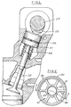
- FIG. 1 is a fragmentary cross sectional view of a direct acting hydraulic tappet in an internal combustion engine.
- FIG. 2 is a bottom plan view of the tappet.
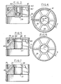
- FIG. 3 is a sectional view taken along the line 3-3 in FIG. 2.
- FIG. 4 is a bottom plan view of the tappet with the hydraulic lash compensating unit removed.
- FIG. 5 is a sectional view taken along the line 5-5 in FIG. 4.
- FIG. 6 is a bottom plan view of the tappet shown in FIG. 5 with the cam face member removed.
- FIG. 7 is a sectional view taken along the line 7-7 in FIG. 6.
- FIG. 8 is a perspective view of an extrusion utilized in making the body shell of the hydraulic tappet.
- FIG. 9 is an end view of the extrusion shown in FIG. 8.
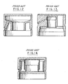
- FIGS. 10-14 are cross sectional views of prior art hydraulic tappets.
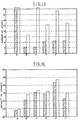
- FIG. 15 is a bar chart of the results of starts to noise tests.
- FIG. 16 is a bar chart of weight tests.
- the direct acting hydraulic tappet 20 embodying the invention is positioned in a bore 21 of an engine for sliding movement axially in the bore 21.
- the tappet 20 is contacted at one end by a cam 22 on a cam shaft 23.
- a spring 24 extends into the tappet 20 and yieldingly urges the tappet 20 against cam 22.
- a valve 25 is operated by the tappet 20, in accordance with conventional construction.
- the tappet 20 comprises a shell 30 (FIGS. 6, 7) that consists of a one piece extruded body that includes an outer cylinder 31, an inner cylinder 32 and a plurality of axially extending webs 33 integrally connecting the outer cylinder 31 and the inner cylinder 32. Intermediate its ends, the outer cylinder 31 is formed with an annular groove 34.
- the inner cylinder 32 has a lesser length than the outer cylinder 31.
- the upper end of each web 33 is machined to form an annular recess 35 adjacent the inner cylinder 32 and a second annular recess 36 of greater axial dimension adjacent the outer cylinder 31.
- the inner surface 37 of the inner cylinder 32 is formed with a shoulder 38.
- a hydraulic lash compensating assembly 39 is provided within the inner cylinder 32, as is well known in the art.
- the shell 30 further includes an oil passage 40 that extends from the groove 34 axially upwardly and inwardly to the upper end of the cavity formed by the inner surface of the cylinder 32 (FIGS. 5, 7).
- the hydraulic tappet 20 further includes a camface member 41 on the upper end of shell 30 and has an integral annular axial wall 42 extending into the recess 36 and a radial flange 43 engaging the upper end of the outer cylinder 31.
- Cam face 41 includes a recess 44 on the underside adjacent the upper end of passage 40.
- the camface member 41 is made of hardened steel, cast iron or ceramic and is attached to the body shell 30 by electromagnetic forming, adhesive bonding or both.
- the shell is preferably made of a lightweight metal such as aluminum.
- the body shell is formed from a bar 50 that is formed by continuous extrusion so that it has an outer cylinder 31a, an inner cylinder 32a and axial webs 33a.
- the extruded body 50 is cut into lengths and then the body shell is machined from such lengths.
- the outer surface of the outer cylinder 31 is preferably anodized with Teflon impregnation, Teflon being a registered trademark of Dupont.
- FIGS. 10-14 show prior art tappets: FIG. 10 is a drawing of a prior art tappet such as shown in United States patents 4,995,353 and 5,119,774 without the foam filling; FIG. 11 is a drawing of the prior art tappet shown in United States patent 4,602,409; FIG. 12 is a drawing of the prior art tappet shown in United States patents 4,590,898 and 4,270,496; FIG. 13 is a drawing of a prior art tappet such as shown in United States patent 4,367,701; and FIG. 14 is a drawing of prior art tappet shown in FIG. 11a of SAE Technical Paper Series 900451 titled Performance of Hydraulic Lash Adjusters With Regard to Valve Train Noise at Cold Starts and Short Term Start, International Congress and Exposition, Detroit, Michigan, February 26-March 2, 1990.
- FIG. 15 is a comparative summary of Starts to Noise of various tappets wherein:
- the clear bar represents the start number when the engine failed to quiet within the 5 second duration of the test.
- the cross hatched bar indicates the start number when noise was first noticed, but the engine did quiet during the 5 seconds.
- FIG. 16 is a graphic summary of comparative weight tests of these tappets.
- the clear bar indicates the weight of the tappet when filled with engine oil.
- the cross hatched bar is the weight of the tappet when empty.
- the tappet embodying the invention has the least weight.
- each of the prior art designs has a shell defining a reservoir and having a transverse or radial wall perpendicular to the axis of the shell.
- the disadvantage of existing designs is that the rough shape of the part must be machined or formed, one piece at a time.
- the new design in accordance with the present invention eliminates the perpendicular (radial) cross member and replaces it with cross members or webs that are parallel (axial) with respect to the inner cylinder and outer cylinder leaving both ends of the part open. This allows the basic form of this part to be continuously extruded in bar form. This significantly reduces the cost of manufacturing this part.
- the wear resistant camface is then attached using an innovative attachment method.
- Current methods of attachment include welding, brazing or capturing the camface within the outer cylinder and supporting it on the perpendicular cross member.
- This new method of the present invention uses electromagnetic forming and/or adhesive bonding to attach the cap to the cylinder. This allows attaching an aluminum housing directly to a wear resistant steel or cast iron cap without the perpendicular cross member between the cap and the hydraulic element. This reduces both the height and weight of the tappet. Reduced tappet height in this type of application directly reduces the overall engine height which allows for a more aerodynamic hood shape. The lighter weight allows for higher engine RPM's due to less reciprocating mass.
- the oil is supplied directly to the hydraulic element through a hole 40 in one or more of the axial cross member or webs 33. This eliminates the need for a cavity or reservoir in the shell. This further reduces the operational weight of the tappet. It also reduces the start up noise of the tappet. In current designs, the reservoir drains when the engine is shut off, this reservoir must refill before oil can reach the hydraulic element. In this design of the present invention, there is no reservoir to refill, so oil is supplied much more quickly to the lash element.
- the outside surface of the outer cylinder of the present invention uses a novel coating, namely, Teflon impregnation during the anodizing process is used to reduce friction and wear of this surface.
- hydraulic tappet embodying the invention is less costly to manufacture; has less weight; easier to manufacture and is very quiet in start-stop tests.
Landscapes
- Engineering & Computer Science (AREA)
- Mechanical Engineering (AREA)
- General Engineering & Computer Science (AREA)
- Valve-Gear Or Valve Arrangements (AREA)
Claims (13)
- Direkt wirkender hydraulischer Ventilstößel (20) für eine Brennkraftmaschine, umfassend eine einstückige Körperhülse (30) mit einem Außenzylinder (31) und einem Innenzylinder (32), die durch eine Anzahl von Stegen (33) miteinander verbunden sind,ein am einen Ende der Körperhülse (30) angebrachtes Nockenflächenglied (41),eine von der Außenfläche des Außenzylinders (31) durch einen der Stege (33) zu einer Innenfläche des Innenzylinders (32) verlaufende Ölbohrung (40) undeine im Innenzylinder (32) angeordnete hydraulische Spielausgleicheinheit (39), dadurch gekennzeichnet, daßi) die Körperhülse (30) ein von einem Aluminiumstab, der durch Strangpressen geformt ist, (ab)geschnittenes (Längen-)Stück umfaßt undii) die Stege (33) parallel zur Achse der Körperhülse verlaufen.
- Hydraulischer Ventilstößel nach Anspruch 1, wobei der Außenzylinder (31) eine Außenfläche aufweist, die anodisiert und mit Polytetrafluorethylen imprägniert ist.
- Hydraulischer Ventilstößel nach Anspruch 1, wobei das Nockenflächenglied (41) aus gehärtetem Stahl besteht.
- Hydraulischer Ventilstößel nach Anspruch 1, wobei das Nockenflächenglied (41) aus Gußeisen besteht.
- Hydraulischer Ventilstößel nach Anspruch 1, wobei das Nockenflächenglied (41) aus Keramik besteht.
- Hydraulischer Ventilstößel nach Anspruch 1, wobei das Nockenflächenglied (41) mit dem Körper durch an der Körperhülse (30) vorgenommene (formed) elektromagnetische Verformung vereinigt ist.
- Hydraulischer Ventilstößel nach Anspruch 1, wobei das Nockenflächenglied (41) an der Körperhülse (30) festhaftend angebracht ist.
- Hydraulischer Ventilstößel nach Anspruch 1, wobei das Nockenflächenglied (41) mit der Körperhülse (30) mit Hilfe von Klebmittel verbunden ist.
- Hydraulischer Ventilstößel nach Anspruch 1, wobei die Stege (33) flach sind.
- Verfahren zur Herstellung eines hydraulischen Ventilstößels (20) für eine Brennkraftmaschine, umfassend: (kontinuierliches) Strangpressen einer (eines) Stange oder Stabs aus Aluminium mit einem Querschnitt, der einen Außenzylinder (31), einen Innenzylinder (32) sowie Innen- und Außenzylinder (32 bzw. 31) verbindende und parallel zur Achse der Stange bzw. des Stabs verlaufende, materialeinheitliche Stege (33) festlegt,Abtrennen eines Abschnitts der Stange bzw. des Stabs zur Bildung einer Ventilstößel-Körperhülse (30),Verbinden eines Nockenflächenglieds (41) mit der Körperhülse undFormen einer vom Umfang des Außenzylinders (31) zur Innenfläche des Innenzylinders (32) verlaufenden Ölbohrung (40).
- Verfahren nach Anspruch 10, mit dem Schritt des Anbringens eines Nockenflächenglieds (41) am einen Ende der Körperhülse.
- Verfahren nach Anspruch 11, wobei der Schritt des Anbringens des Nockenflächenglieds (41) durch elektromagnetisches Formen oder Umformen durchgeführt wird.
- Verfahren nach Anspruch 11, wobei der Schritt des Anbringens des Nockenflächenglieds (41) an der Körperhülse (30) durch klebendes Verbinden des Nockenflächenglieds (41) mit der Hülse (30) durchgeführt wird.
Applications Claiming Priority (2)
| Application Number | Priority Date | Filing Date | Title |
|---|---|---|---|
| US08/079,240 US5320074A (en) | 1993-06-17 | 1993-06-17 | Direct acting hydraulic tappet |
| US79240 | 1993-06-17 |
Publications (2)
| Publication Number | Publication Date |
|---|---|
| EP0631035A1 EP0631035A1 (de) | 1994-12-28 |
| EP0631035B1 true EP0631035B1 (de) | 1997-04-23 |
Family
ID=22149286
Family Applications (1)
| Application Number | Title | Priority Date | Filing Date |
|---|---|---|---|
| EP94304309A Expired - Lifetime EP0631035B1 (de) | 1993-06-17 | 1994-06-14 | Direkt wirkender hydraulischer Ventilstössel |
Country Status (4)
| Country | Link |
|---|---|
| US (1) | US5320074A (de) |
| EP (1) | EP0631035B1 (de) |
| JP (1) | JPH07166825A (de) |
| DE (1) | DE69402764T2 (de) |
Families Citing this family (4)
| Publication number | Priority date | Publication date | Assignee | Title |
|---|---|---|---|---|
| JPH06280513A (ja) * | 1993-03-30 | 1994-10-04 | Ngk Insulators Ltd | 油圧式タペット |
| US5445119A (en) * | 1994-12-09 | 1995-08-29 | Chrysler Corporation | Tappet and shim assembly for internal combustion engine |
| DE19542697A1 (de) * | 1995-11-16 | 1997-05-22 | Schaeffler Waelzlager Kg | Stößel für einen Ventiltrieb einer Brennkraftmaschine |
| CN102517619B (zh) * | 2011-12-09 | 2014-07-16 | 杰锋汽车动力系统股份有限公司 | 一种机械挺柱结构的加工处理方法 |
Family Cites Families (29)
| Publication number | Priority date | Publication date | Assignee | Title |
|---|---|---|---|---|
| US2925803A (en) * | 1958-12-16 | 1960-02-23 | Gen Dynamics Corp | Actuating pressure release system |
| US3545415A (en) * | 1967-04-08 | 1970-12-08 | Nippon Piston Ring Co Ltd | Valve lifter with thin plastic coating |
| US3618575A (en) * | 1969-08-28 | 1971-11-09 | Johnson Products Inc | Metering mechanical tappet |
| US3657800A (en) * | 1969-12-29 | 1972-04-25 | Caterpillar Tractor Co | Friction welded graphitic valve lifters |
| IT7853889V0 (it) * | 1978-11-15 | 1978-11-15 | Fiat Spa | Punteria idraulica a ripresa automatica del gioco per motori a combustione interna con alberi a camme in testa |
| US4270496A (en) * | 1978-12-26 | 1981-06-02 | Eaton Corporation | Welded article and method of making same |
| FR2460178A1 (fr) * | 1979-07-03 | 1981-01-23 | Gachot Jean | Procede pour la fabrication d'un piston et pistons en resultant |
| DE2942926A1 (de) * | 1979-10-24 | 1981-05-07 | IRM-Antriebstechnik GmbH, 7057 Winnenden | Tassenstoessel mit hydraulischem ventilspielausgleich |
| US4470381A (en) * | 1979-12-05 | 1984-09-11 | Eaton Corporation | Hydraulic tappet for direct-acting valve gear |
| US4367701A (en) * | 1979-12-05 | 1983-01-11 | Eaton Corporation | Acting valve gear |
| US4590898A (en) * | 1979-12-05 | 1986-05-27 | Eaton Corporation | Hydraulic tappet for direct-acting valve gear |
| US4373477A (en) * | 1980-12-29 | 1983-02-15 | Eaton Corporation | Lash adjuster with plunger retainer |
| DE3409235A1 (de) * | 1984-03-14 | 1985-09-19 | Motomak Motorenbau, Maschinen- u. Werkzeugfabrik, Konstruktionen GmbH, 8070 Ingolstadt | Aeusseres fuehrungsteil fuer einen ventilstoessel fuer verbrennungskraftmaschinen |
| DE3412153A1 (de) * | 1984-03-31 | 1985-10-10 | Motomak Motorenbau, Maschinen- u. Werkzeugfabrik, Konstruktionen GmbH, 8070 Ingolstadt | Verfahren zum befestigen eines trichterfoermigen fuehrungsteiles in der bohrungswand des tassenfoermigen gehaeuses eines sich selbsttaetig hydraulisch einstellenden ventilstoessels |
| JPH0799083B2 (ja) * | 1984-07-04 | 1995-10-25 | ヤマハ発動機株式会社 | 軽合金製動弁用タペツト |
| IT8454108U1 (it) * | 1984-12-04 | 1986-06-04 | Riv Skf Officine Di Villar Perosa S P A | Punteria idraulica a tenuta stagna per il comando del moto di una valvola di un motore endotermico. |
| JPS62255507A (ja) * | 1986-04-30 | 1987-11-07 | Hitachi Ltd | バルブリフタ−の製造方法 |
| US4909198A (en) * | 1988-03-01 | 1990-03-20 | Toyota Jidosha Kabushiki Kaisha | Aluminum alloy valve lifter with sprayed coating and method of producing same |
| DE3828635A1 (de) * | 1988-08-24 | 1990-03-08 | Daimler Benz Ag | Verfahren zum herstellen von tassenstoesseln fuer hubkolbenmaschinen |
| DE3919777C1 (de) * | 1989-06-16 | 1990-06-21 | Daimler-Benz Aktiengesellschaft, 7000 Stuttgart, De | |
| US5060607A (en) * | 1989-06-21 | 1991-10-29 | Ngk Spark Plug Co., Ltd. | Tappet structure |
| DE3920729A1 (de) * | 1989-06-24 | 1991-01-10 | Gmb Giesserei & Maschinenbau B | Tassenstoesselkoerper fuer ventilstoessel |
| DE4005261A1 (de) * | 1990-02-20 | 1991-08-22 | Bayerische Motoren Werke Ag | Tassenstoessel mit einem hydraulischen ventilspiel-ausgleichselement |
| US4995353A (en) * | 1990-04-11 | 1991-02-26 | General Motors Corporation | Valve train with lash/compliance compensation |
| JPH0518213A (ja) * | 1990-07-20 | 1993-01-26 | Ngk Spark Plug Co Ltd | エンジン用タペツト |
| US5245958A (en) * | 1990-11-08 | 1993-09-21 | General Motors Corporation | Direct acting hydraulic valve lifter |
| US5119774A (en) * | 1990-11-08 | 1992-06-09 | General Motors Corporation | Direct acting hydraulic valve lifter |
| US5070827A (en) * | 1991-04-01 | 1991-12-10 | General Motors Corporation | Low mass valve lifters |
| DE4140244B4 (de) * | 1990-12-19 | 2005-09-22 | Volkswagen Ag | Ventilspielausgleichsvorrichtung für ein Hubventil |
-
1993
- 1993-06-17 US US08/079,240 patent/US5320074A/en not_active Expired - Fee Related
-
1994
- 1994-06-13 JP JP6130600A patent/JPH07166825A/ja active Pending
- 1994-06-14 DE DE69402764T patent/DE69402764T2/de not_active Expired - Fee Related
- 1994-06-14 EP EP94304309A patent/EP0631035B1/de not_active Expired - Lifetime
Also Published As
| Publication number | Publication date |
|---|---|
| DE69402764T2 (de) | 1997-10-23 |
| JPH07166825A (ja) | 1995-06-27 |
| US5320074A (en) | 1994-06-14 |
| DE69402764D1 (de) | 1997-05-28 |
| EP0631035A1 (de) | 1994-12-28 |
Similar Documents
| Publication | Publication Date | Title |
|---|---|---|
| EP0030780B1 (de) | Leichtgewicht-Ventilstössel für direkt wirkende Ventilvorrichtung | |
| EP0615056B1 (de) | Ventilstössel mit Rolle | |
| EP0030781B1 (de) | Hydraulischer Ventilstössel für eine direkt angetriebene Ventilsteuerung | |
| JP4159605B2 (ja) | 内燃機関の弁制御部のための液力式の支持エレメント | |
| US4590898A (en) | Hydraulic tappet for direct-acting valve gear | |
| US4470381A (en) | Hydraulic tappet for direct-acting valve gear | |
| GB2108620A (en) | Hydraulic lifter | |
| KR20100030621A (ko) | 냉동 컴프레서용 피스톤 | |
| US6499387B2 (en) | Unified multi-piece piston and method of manufacture | |
| US5320074A (en) | Direct acting hydraulic tappet | |
| JP2634988B2 (ja) | 内燃機関動弁装置用タペット | |
| JP2006514722A (ja) | 内燃機関の燃料噴射装置用の高圧ポンプ | |
| US5014599A (en) | Two piece hydraulic piston assembly with swaged piston-sleeve joint | |
| KR100282289B1 (ko) | 내연기관의 밸브 드라이브용 태핏 | |
| KR920000239B1 (ko) | 분리된 저널에 배치된 슬리이브를 팽창시킴으로써 조립되는 크랭크 샤프트의 제조방법 | |
| US5226389A (en) | Direct acting tappet | |
| JPH0647925B2 (ja) | 自動的に油圧で調節される弁タペット | |
| USRE32167E (en) | Acting valve gear | |
| EP0140674A2 (de) | Spielausgleichselement mit eingebetteter Verschleissfläche | |
| EP1619359A1 (de) | Hydraulisches Spielausgleichselement mit vereinfachtem Kolbenteil | |
| EP0225096A1 (de) | Hydraulischer Tassenstössel mit eigenem Ölkreislauf | |
| US20030041825A1 (en) | Tappet for an internal combustion engine | |
| US5458097A (en) | Light weight valve lifter | |
| US7261075B2 (en) | Hydraulic support element | |
| US5230308A (en) | Low mass direct acting hydraulic valve lifter |
Legal Events
| Date | Code | Title | Description |
|---|---|---|---|
| PUAI | Public reference made under article 153(3) epc to a published international application that has entered the european phase |
Free format text: ORIGINAL CODE: 0009012 |
|
| AK | Designated contracting states |
Kind code of ref document: A1 Designated state(s): DE FR GB IT |
|
| 17P | Request for examination filed |
Effective date: 19950615 |
|
| 17Q | First examination report despatched |
Effective date: 19951030 |
|
| GRAG | Despatch of communication of intention to grant |
Free format text: ORIGINAL CODE: EPIDOS AGRA |
|
| GRAH | Despatch of communication of intention to grant a patent |
Free format text: ORIGINAL CODE: EPIDOS IGRA |
|
| GRAH | Despatch of communication of intention to grant a patent |
Free format text: ORIGINAL CODE: EPIDOS IGRA |
|
| GRAA | (expected) grant |
Free format text: ORIGINAL CODE: 0009210 |
|
| AK | Designated contracting states |
Kind code of ref document: B1 Designated state(s): DE FR GB IT |
|
| REF | Corresponds to: |
Ref document number: 69402764 Country of ref document: DE Date of ref document: 19970528 |
|
| ET | Fr: translation filed | ||
| PLBE | No opposition filed within time limit |
Free format text: ORIGINAL CODE: 0009261 |
|
| STAA | Information on the status of an ep patent application or granted ep patent |
Free format text: STATUS: NO OPPOSITION FILED WITHIN TIME LIMIT |
|
| 26N | No opposition filed | ||
| PGFP | Annual fee paid to national office [announced via postgrant information from national office to epo] |
Ref country code: FR Payment date: 19990519 Year of fee payment: 6 |
|
| PGFP | Annual fee paid to national office [announced via postgrant information from national office to epo] |
Ref country code: GB Payment date: 19990520 Year of fee payment: 6 |
|
| PGFP | Annual fee paid to national office [announced via postgrant information from national office to epo] |
Ref country code: DE Payment date: 19990521 Year of fee payment: 6 |
|
| PG25 | Lapsed in a contracting state [announced via postgrant information from national office to epo] |
Ref country code: GB Free format text: LAPSE BECAUSE OF NON-PAYMENT OF DUE FEES Effective date: 20000614 |
|
| GBPC | Gb: european patent ceased through non-payment of renewal fee |
Effective date: 20000614 |
|
| PG25 | Lapsed in a contracting state [announced via postgrant information from national office to epo] |
Ref country code: FR Free format text: LAPSE BECAUSE OF NON-PAYMENT OF DUE FEES Effective date: 20010228 |
|
| REG | Reference to a national code |
Ref country code: FR Ref legal event code: ST |
|
| PG25 | Lapsed in a contracting state [announced via postgrant information from national office to epo] |
Ref country code: DE Free format text: LAPSE BECAUSE OF NON-PAYMENT OF DUE FEES Effective date: 20010403 |
|
| PG25 | Lapsed in a contracting state [announced via postgrant information from national office to epo] |
Ref country code: IT Free format text: LAPSE BECAUSE OF NON-PAYMENT OF DUE FEES Effective date: 20050614 |