EP0630179B1 - Frontkraftheber für traktor oder dergleichen - Google Patents
Frontkraftheber für traktor oder dergleichen Download PDFInfo
- Publication number
- EP0630179B1 EP0630179B1 EP93918744A EP93918744A EP0630179B1 EP 0630179 B1 EP0630179 B1 EP 0630179B1 EP 93918744 A EP93918744 A EP 93918744A EP 93918744 A EP93918744 A EP 93918744A EP 0630179 B1 EP0630179 B1 EP 0630179B1
- Authority
- EP
- European Patent Office
- Prior art keywords
- forearm
- forearms
- framework
- frame
- spindle
- Prior art date
- Legal status (The legal status is an assumption and is not a legal conclusion. Google has not performed a legal analysis and makes no representation as to the accuracy of the status listed.)
- Expired - Lifetime
Links
Images

Classifications
-
- A—HUMAN NECESSITIES
- A01—AGRICULTURE; FORESTRY; ANIMAL HUSBANDRY; HUNTING; TRAPPING; FISHING
- A01B—SOIL WORKING IN AGRICULTURE OR FORESTRY; PARTS, DETAILS, OR ACCESSORIES OF AGRICULTURAL MACHINES OR IMPLEMENTS, IN GENERAL
- A01B59/00—Devices specially adapted for connection between animals or tractors and agricultural machines or implements
- A01B59/04—Devices specially adapted for connection between animals or tractors and agricultural machines or implements for machines pulled or pushed by a tractor
- A01B59/048—Devices specially adapted for connection between animals or tractors and agricultural machines or implements for machines pulled or pushed by a tractor having pulling or pushing means arranged on the front part of the tractor
-
- B—PERFORMING OPERATIONS; TRANSPORTING
- B62—LAND VEHICLES FOR TRAVELLING OTHERWISE THAN ON RAILS
- B62D—MOTOR VEHICLES; TRAILERS
- B62D49/00—Tractors
- B62D49/08—Tractors having means for preventing overturning or tipping
- B62D49/085—Counterweight
Definitions
- the invention relates to a front lifting device, for agricultural tractor or the like, making it possible to couple a tool to the front of the tractor in order to raise and / or lower it
- this device being of the type of those which comprise a frame intended to be fixed to the chassis of the tractor, said frame being equipped, at the bottom, with lower attachment means extending forward, articulated around a transverse axis, and at the ends of which can hook the two low points of attachment of a tool, and, in the upper part, of a middle upper attachment means, for a connection with a third point of attachment of the tool, and means lifting, in particular hydraulic, provided between the frame and the lower attachment means for ensuring the movements of ascent or descent
- the lower attachment means comprising, on the one hand, a primary articulated lower frame, at its rear part, on a tran axis sversal carried by the frame, and provided towards the front with two lateral longitudinal extensions in each of which is provided a transverse bearing, and, on the other hand, an forearm associated with each longitudinal
- a device of this type is known, in particular from EP-A-0 182 091.
- the forearms can be placed and held in the raised position, by the lifting means, to reduce as much as possible the front dimensions of the front lifting device.
- the lifting means can cause the lowering of the forearms when such a lowering is not desired and can be annoying, or even dangerous.
- the invention aims, in particular, to provide a lifting device which makes it possible to avoid unfortunate consequences in the event of actuation of the lifting means, while the forearms are raised and must remain so.
- the lifting device can also be a nuisance, in particular if the operator wishes to mount a front loader at the front of his tractor. In such a case, the operator may have to dismantle the front lifting device beforehand and then install his front loader.
- This dismantling operation of the front linkage constitutes an annoying constraint and a brake on the expansion of the front linkage devices.
- EP-A-0 274 853 describes, of course, a lifting device allowing compatibility with a front loader.
- the design of this lifting device limits the ground clearance and the turning radius at work, because, for a fall on each side of the tractor, a sufficiently large lift is required which interferes with the wheels when they are turned.
- the invention aims, above all, to provide a front lifting device which no longer has or to a lesser degree the drawbacks mentioned above. It is desired that when this front lifting device is in the storage position on the tractor, it cannot be put into the working position if the lifting means are actuated by error or accidentally. It is further desired that this device is not only compatible with a front loader but also that it does not limit the maneuverability of the tractor. It is also desired that such a front lifting device does not constitute an obstacle to the passage of a movement transmission from the front PTO of the tractor.
- the front lifting device allowed free flotation of the tool if desired, as well as adjustment of the inclination of the tool, or complete locking.
- the installation and adjustment of the front lifting device must be as simple and quick as possible.
- a front lifting device for agricultural tractor or the like, making it possible to couple a tool to the front of the tractor in order to raise and lower it, of the kind defined above, is characterized by the fact that the lifting means are connected to the frame, lower and to the framework, that the two forearms are independent of each other, that each forearm comes to bear by its rear part, when it is in the working position, under a stop integral with the frame so as to lock during lifting of the frame and lifting of a load, and that the fixed locking of the forearms, in the high position of the frame makes it possible to prevent movement of the frame even if the operator inadvertently controls the lifting means.
- the framework comprises means for locking the forearms of the frame in the high position, by combination of the movement of the primary movable lower frame, upwards, folding of the forearms relative to the frame upwards, and hooking of the fronts. -arm on a support and locking member provided on the frame.
- the support and locking member is constituted by a pin on which the end of the forearms is hooked.
- the framework may include, in the upper part, bearings similar to those carried by the extensions of the lower frame, these bearings being provided, when the assembly is in working position, auxiliary axes similar to those of the forearms, provided with longer extensions than those of the forearms, the assembly being such as for locking the forearms, in the raised position of the frame lower, the auxiliary axes of the bearings of the framework are removed from these bearings, while the forearms are dismounted from the extensions and returned so as to be placed inside the framework with their axes received in the high bearings of the framework, while the axes auxiliaries are mounted in the bearings of the lateral extensions with their extensions facing inwards, the assembly being such that the ends of the forearms are hooked onto the extensions of said auxiliary axes when the lower frame is raised.
- Each lateral extension may comprise two members separated by a space in which is received a connecting member constituting one end of the lifting means, this member being linked to the extension by an axis passing through openings provided in the members, while the bearing provided at the end of the lateral extension is constituted by a sleeve of transverse axis.
- each forearm can be fixed on the latter so as to be able to be inserted quickly into the bearing of the corresponding extension, without tools, the arm being located outside the extension.
- each forearm may include a smaller diameter extension intended to be located between the extensions of the frame when the arm is mounted, this extension being able to be used where appropriate for the attachment of accessories, in particular to the '' attachment of a mass carrier.
- the extension is provided with means for stopping the axis relative to the bearing, with possible interposition of washers, in the axial direction of this bearing.
- each axis has a reduced length so that there is sufficient space between the ends opposite the extensions, when the two forearms are mounted, for the passage of a mechanical transmission from the front PTO of the tractor.
- Each forearm may comprise, towards its rear end, a piton oriented substantially orthogonally to the longitudinal direction of the forearm and situated beyond the axis of articulation of the forearm, this piton being clean through an opening provided in a stop integral with the frame, located above the rear part of the forearm.
- the piton receives a set of washers of variable thickness and is provided with means for stopping the oscillation of the forearm, so as to allow various possible adjustments for this forearm, namely oscillating, fixed, or forced tilt.
- the means for stopping the axis of a forearm, relative to the bearing can be arranged to allow rapid unlocking of the forearm for transverse sliding so that when the forearm is equipped at its end with a ball joint with bore, it is possible, by transverse sliding, to bring the bore of this ball joint in front of a stud carried by the frame, in the high storage position, and by sliding in the opposite direction, to engage the pin in the bore of said ball to ensure locking in the storage position.
- the device can be arranged so that the folded forearms, in the storage position, have a substantially vertical front face having the function of a shield.
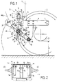
- Figure 1 of these drawings is a side view, in elevation, of a coupling device according to the invention.
- Figure 2 is a partial view, on the left with respect to Figure 1, of the framework.
- FIG. 3 is a plan view of the coupling device of FIG. 1.
- Figure 4 is a section along the line IV-IV in Figure 3.
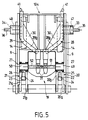
- Figure 5 is a partial front view of an alternative embodiment of the front coupling device, in the storage position.
- a front lifting device D for an agricultural tractor 1 very briefly shown including a front wheel 2 is also briefly shown.
- the ground clearance G of the tractor 1 at the front corresponds to the distance between the ground and the lowest point of the contour 3 enveloping the lower parts of the front axle, or the like.
- the device D comprises a frame 4 intended to be fixed to the chassis of the tractor 1.
- the frame 4 comprises two external sides such as 5 fixed respectively to the right and left of the tractor chassis between the front wheels.
- Each sidewall 5 comprises a rectangular plate 6 situated in a substantially vertical plane, the large dimension of which is horizontal, this plate comprising several holes 7 towards its front and rear ends for fixing to the chassis in an area located above the wheel axle 2.
- a console 8 projects upwards at the front of the plate 6; this console 8 is constituted in particular by a vertical sheet substantially coplanar with the plate 6, welded to this plate.
- the console 8 comprises a stretcher 9 extending downwards and the lower end 10 of which is situated at a distance from the ground equal to or greater than the distance G.
- the console 8 also comprises an upright 11 extending at one level higher than plate 6, towards the front.
- a central part 12 of the framework provides a rigid connection between the upper parts of the uprights 11.
- gussets 13 are fixed, in particular by welding, at a reduced distance from the uprights 11.
- a hole is provided in the upright 11 and the neighboring gusset 13 to serve as support for an axis h used for an articulated fixing of a hydraulic cylinder 14 constituting a lifting means, on each side.
- plates 15 On either side of the mediator plane of the central part 12 are provided plates 15 having opposite holes to serve as support for a pin 16 used to attach a third point bar such as the bar 17 shown in Figure 7 .
- the frame 4 is equipped, in the lower part, with lower attachment means A articulated around a transverse axis 18 carried by bearings provided in the vicinity of the lower end 10 of the stretchers 9. It thus appears that the lower point of attachment of the means A does not cause a reduction in the ground clearance G of the tractor, nor interference with a front PTO F.
- the position in a horizontal plane of the axis of rotation 18 of the stretchers is chosen so that the lever arm L defined relative to the position of the anchoring point of the jacks 14 is sufficient for the diameter of the cylinder of the jacks 14 remains compatible with the place necessary to introduce and extract the pin 16 for hooking the third point.
- the attachment means A comprise a primary lower frame 19 articulated, at its rear part, on the transverse axis 18.
- the frame 19 is provided, towards the front, with two lateral longitudinal extensions 20, 21.
- Each lateral extension comprises two members 20a, 20b, 21a, 21b separated by a space in which is received a connecting member such as a ball 22, 23 mounted at the end of the rod of each jack 14 for lifting.
- the ball 22, 23 is linked to the corresponding extension 20, 21, by an axis passing through this yoke and received, at its ends, in holes 24, provided in each member.
- a transverse bearing 25, 26 constituted by a tubular sleeve with an axis transverse parallel to the articulation axis 18 of the frame 19.
- This sleeve 25, 26 is fixed, at 27, to these members, in particular by welding.
- the open bearings 25, 26 make it possible to easily accommodate wear rings facilitating maintenance.
- the lower attachment means A comprise two forearms 28, 29 associated respectively with each lateral extension 20, 21.
- Each forearm is bent so that its front part deviates from the middle central direction, the concavity of the arm being turned outwards. This makes it possible to obtain, between the front ends of the forearms, a distance in accordance with the coupling standards.
- a stiffening web 30, for example welded, is provided in the concavity of each arm. At the front end of each forearm is fixed, by welding, either a hand 31 (FIG.
- a hinge pin 33, 34 is fixed on the internal face of the respective forearms 28, 29, in a direction orthogonal to the forearm.
- This axis 33, 34 has an outside diameter equal, apart from the operating clearance, to that of the bore of the bearing 25, 26, corresponding, so as to be able to be quickly inserted from the outside into the bearing, and to be disassembled without tools.
- Each axis 33, 34 has an extension of small diameter 35, 36, coaxial, intended to be in the space between the extensions 20, 21 of the frame, when the forearm is mounted.
- Each extension 35, 36 is provided, at its inner end, with a stop means constituted for example by a diametral bore 37 suitable for receiving a pin 37 a which, combined with a spacer 38 engaged on the extension 35 and bearing against the inner face of the bearing 25 or 26, allows transversely blocking the corresponding forearm relative to the frame 19, while leaving freedom of rotation to this forearm around the axis of the bearing.
- extensions 35, 36 allow the attachment of a mass carrier illustrated in FIGS. 6 and 7.
- the length of these extensions 35, 36 is sufficient to ensure satisfactory attachment, but is not too great. so that a free space remains between the internal ends opposite the extensions 35, 36 to allow the passage of a transmission from the front PTO F of the tractor.
- Each forearm 28, 29 extends rearwardly beyond its hinge axis 35, 36 along a branch 28a, 29a.
- the rear end of each branch 28a, 29a comes to bear under a stop 39, 40.
- stops 39, 40 may be constituted by thick plates fixed under the frame 19, in particular by welding, and projecting laterally from the outline of this frame, above the rear ends of the forearms. During the lifting movement of the frame 19, if a load is attached to the end of the forearms 28, 29, the latter are locked in rotation by the stops 39 and 40. On the other hand, the forearms 28, 29 , can be folded up, the rear end of these forearms then deviating from the stops 39, 40.
- the forearms 28, 29 are independent and can pivot in a different manner, which allows a tool, carried by these arms, to perform a rotational movement around a plurality of longitudinal axes, for free flotation ensuring relief monitoring.
- Each forearm has, towards its rear end, a peak 41 directed upwards, substantially orthogonal to the longitudinal direction of the forearm.
- This piton 41 constituted for example by a piece of cylindrical rod, is suitable for passing through an elongated opening 42 provided in the corresponding stop 39, 40.
- the piton 41 comprises, towards its upper end, a stop means advantageously constituted by the combination of a diametral hole 43 and a pin 43 a , engaged in this hole, to block or limit the possible oscillation of the forearm relative to the frame 19.
- the adjustment is obtained by threading on the stud 41, washers 44.
- the arm has no freedom of oscillation.
- the forearm retains a certain freedom of oscillation until it comes into contact with the pin 43a with the upper washer. It is also possible to place washers such as 44 below the stops 39, 40 so as to impose a forced inclination on the corresponding forearm.
- the framework 4 comprises, in the upper part, locking means V of the lifting device in the high storage position, when this device is not used.
- the locking position illustrated in dashed lines in FIG. 1 is obtained by combination of the movement of the lower frame 19 upwards and the forearms 28 folded back, relative to the frame 19, upwards after removal of any pins provided on the pegs 41.
- the locking means V comprise in lateral projection on each side of the frame 4, in the upper part, a stud 45 rigidly fixed on the frame.
- This pin 45 can be either equipped with a ball used for hanging the tools and on which the self-locking hand 31 is hooked, or engaged in the bore of the ball joint hand 32, when the jacks 14 are in the maximum lifting position and that the corresponding forearm is tilted up.
- the assembly is designed so that in this locking position, as visible in FIG. 1, the forearm 28, 29 is substantially vertical and constitutes a shield.
- the angle s formed between the axis of the jack 14 and the mean direction of the forearm 29 locked in the high position is relatively low, less than 30 °. If the operator inadvertently controls the output of the rod of the jack 14, the forearm works essentially in traction; the locking is sufficient to withstand the force generated by the jacks 14.
- the hydraulic distributor used for the operation of the jacks 14 can be released, after disconnecting the hydraulic jacks for connecting the jacks, for another use.
- the assembly is designed so that in the storage position shown in FIG. 1, the lifting device does not interfere with a front loader mounted at the front of the tractor, and of which only the element located furthest back , namely a crosspiece 46, is shown.
- the portion of curve 47 represents part of the trajectory of the cross member 46 during movements of the front loader, this curve 47 constituting in a way the limit with which the lifting device must not interfere to allow the movements of the front loader to be free.
- the cylinders 14 can work in double effect.
- the forearms 28, 29 extend the lateral extensions and the pins 41 are engaged in the openings 42.
- the forearms can be immobilized in rotation relative to the frame 19 by a set of washers 44 of sufficient thickness, or can retain a certain freedom in oscillation allowing monitoring of the relief.
- the movements of raising or lowering of the tool are controlled by the jacks 14.
- the user controls, from the tractor cabin, the extreme high position of the frame 19 by bringing the rod of the cylinders 14 in the corresponding cylinders.
- the operator can then, on the ground, successively unlock each peak 41 and tilt the corresponding forearm upwards until it is locked on a stud 45, in a substantially vertical position.
- front ends 28 b , 29 b bent towards the outside of the forearms 28, 29 make it possible to substantially reduce the transverse dimension of the frame 19 while retaining, at the level of the attachment hands 31, 32, the width usual.
- the bent portions 28 b , 29 b are relatively forward and the risk of interference with the wheels such as 2 of the tractor, during a turning, are nonexistent.
- the bent parts 28 b , 29 b of the forearms may be able to interfere with the steered wheels if the arms remain outside the framework 4 as for the embodiment of Figures 1 to 4.
- Auxiliary axes 49, 50 are normally housed in these bearings 47, 48. These axes have coaxial extensions 51, 52, of reduced diameter, equal to that of the extensions 35, 36. When the lifting device is in the working position, the auxiliary axes 49, 50 are carried by the bearings 47, 48 and the extensions 51, 52 project outwards.
- the axes 49, 50 have been extracted from the bearings 47, 48 to be mounted in the bearings 25, 26.
- the extensions 51, 52 are longer than the extensions 35, 36 so that when the axes 49, 50 are mounted in the bearings 25, 26 in place of the axes 33, 34, the inner ends of the extensions 51, 52 are close to each other without being in contact.
- the lower frame 19 and the forearms are identical to those described with reference to the previous figures.
- the operator places the forearm 28 inside the framework 104 by engaging the axis 33 in the bearing 47, the end of the forearm 28 provided with the hand 31 being directed downwards (see figure 5).
- the hands of the forearms are close to each other.
- the operator then controls the lifting of the frame 19 in the extreme high position.
- the bearings 25 and 26 are thus brought up to the height of the hands of the forearms 28, 29.
- the operator introduces into the bearings 25, 26 in the high position, the auxiliary axes 49, 50 with their extensions 51, 52 facing the longitudinal mean plane of the frame.
Landscapes
- Engineering & Computer Science (AREA)
- Life Sciences & Earth Sciences (AREA)
- Mechanical Engineering (AREA)
- Chemical & Material Sciences (AREA)
- Combustion & Propulsion (AREA)
- Transportation (AREA)
- Zoology (AREA)
- Soil Sciences (AREA)
- Environmental Sciences (AREA)
- Agricultural Machines (AREA)
Claims (14)
- Vordere Hebevorrichtung für eine landwirtschaftliche Zugmaschine oder dergleichen, die das Ankoppeln eines Werkzeugs an der Vorderseite der Zugmaschine ermöglicht, um dieses anzuheben und/oder abzusenken, mit einem Gerüst (4, 104) zum Anbringen an dem Chassis der Zugmaschine, wobei das Gerüst im unteren Teil mit einer sich nach vom erstreckenden unteren Verbindungseinrichtung (A) versehen ist, die um eine Querachse schwenkbar gelagert ist, und an deren Enden die beiden unteren Einhängepunkte eines Werkzeugs eingesetzt werden können, und wobei das Gerüst im oberen Teil eine obere mittlere Verbindungseinrichtung (16) zur Verbindung mit einem dritten Einhängepunkt des Werkzeugs sowie eine insbesondere hydraulische Hebeeinrichtung (14) aufweist, die zwischen dem Gerüst (4, 104) und der unteren Verbindungseinrichtung vorgesehen ist, um die Hebe- oder Senkbewegungen zu ermöglichen, wobei die untere Verbindungseinrichtung (A) einerseits einen primären unteren Rahmen (19) aufweist, der an seinem hinteren Bereich an einer von dem Gerüst (4, 104) getragenen Querachse (18) gelagert ist und am vorderen Ende zwei langgestreckte seitliche Verlängerungen (20, 21) aufweist, in denen jeweils ein Querlager (25, 26) vorgesehen ist, und wobei die Verbindungseinrichtung andererseits jeweils mit einer langgestreckten Verlängerung (20, 21) verbundene und um eine von dem Lager getragene Achse (33, 34) schwenkbar gelagerte Auslegerarme (28, 29) aufweist, wobei die Einheit derart ausgebildet ist, daß der jeweilige Auslegerarm (28, 29) in der Arbeitsstellung die seitlichen Verlängerungen nach vom verlängert, wobei sich der Auslegerarm nach hinten über seine Schwenkachse hinaus erstreckt, und wobei der Auslegerarm (28, 29) im lastfreien Zustand relativ zum Gerüst (4, 104) in eine Ruhestellung nach oben geschwenkt werden kann, wobei eine feste Verriegelung der Auslegerarme (28, 29) in der angehobenen Position vorgesehen ist, dadurch gekennzeichnet, daß die Hebeeinrichtung (14) mit dem unteren Rahmen (19) und dem Gerüst (4, 104) verbunden ist, daß die beiden Auslegerarme (28, 29) voneinander unabhängig sind, daß jeder der Auslegerarme (28, 29) in der Arbeitsstellung in Anlage unter einen fest mit dem Rahmen (19) verbundenen Anschlag (39, 40) gelangt, derart, daß er beim Anheben des Rahmens und beim Aufheben einer Last blockiert ist, und daß die feste Verriegelung der Auslegerarme (28, 29) in der angehobenen Stellung des Rahmens (19) ermöglicht, eine Bewegung des Rahmens (19) zu verhindern, selbst wenn der Bediener aus Unachtsamkeit die Hebeeinrichtung (14) betätigt.
- Vorrichtung nach Anspruch 1, dadurch gekennzeichnet, daß das Gerüst (4) eine Einrichtung (V) zum Verriegeln der Auslegerarme (28, 29) des Rahmens (19) in der angehobenen Position durch eine Kombination der Bewegung des bewegbaren primären unteren Rahmens (19) nach oben, ein Schwenken der Auslegerarme (28, 29) nach oben relativ zum Rahmen, und ein Einhaken der Auslegerarme (28, 29) an einem an dem Gerüst (4) vorgesehenen Stütz- und Verriegelungselement (45), aufweist.
- Vorrichtung nach Anspruch 2, dadurch gekennzeichnet, daß das Stütz- und Verriegelungsorgan aus einem Zapfen (45) besteht.
- Vorrichtung nach Anspruch 3, dadurch gekennzeichnet, daß die Enden der Auslegerarme (28, 29) an dem Zapfen (45) einhaken.
- Vorrichtung nach Anspruch 1, dadurch gekennzeichnet, daß das Gerüst (104) zum Verriegeln der Vorrichtung während des Nichtgebrauchs im oberen Bereich Lager (47, 48) aufweist, die den von den Verlängerungen (20, 21) des unteren Rahmens (19) getragenen Lagern (25, 26) ähnlich sind, wobei die Lager (47, 48) in der Arbeitsstellung der Einheit mit Zusatzachsen (49, 50) versehen sind, die denjenigen (33, 34) der Auslegerarme ähnlich und mit Verlängerungen (51, 52) versehen sind, die länger als diejenigen (35, 36) der Auslegerarme sind, wobei die Einheit derart ausgebildet ist, daß zum Verriegeln der Auslegeranne (28, 29) in der angehobenen Stellung des unteren Rahmens (19) die Zusatzachsen (49, 50) der Lager des Gerüsts (104) aus den Lagern (47, 48) gezogen werden, während die Auslegerarme (28, 29) von den Verlängerungen (20, 21) gelöst und derart zurückbewegt werden, daß sie im Inneren des Gerüsts (104) angeordnet sind, wobei ihre Achsen (33, 34) in den oberen Lagern (47, 48) des Gerüsts aufgenommen sind, während die Zusatzachsen (49, 50) in den Lagern (25, 26) der seitlichen Verlängerungen (20, 21) angebracht und ihre Verlängerungen (51, 52) nach innen gerichtet sind, wobei die Einheit derart ausgebildet ist, daß sich die Enden der Auslegerarme (28, 29) an den Verlängerungen der Zusatzachsen festhaken, wenn der untere Rahmen (19) angehoben wird.
- Vorrichtung nach Anspruch 1 oder 5, dadurch gekennzeichnet, daß jede seitliche Verlängerung (20, 21) zwei Schenkel (20a, 20b; 21a, 21b) aufweist, die durch einen Raum voneinander getrennt sind, in denen ein Verbindungsorgan (22, 23) aufgenommen ist, das ein Ende der Hebeeinrichtung (14) bildet, wobei dieses Organ mit der Verlängerung durch eine Achse (24) verbunden ist, die sich durch in den Schenkeln vorgesehene Öffnungen erstreckt, während das am Ende der seitlichen Verlängerung vorgesehene Lager aus einer querverlaufenden Achsmanschette (25, 26) besteht.
- Vorrichtung nach Anspruch 6, dadurch gekennzeichnet, daß die Schwenkachse (33, 34) jedes Auslegerarms (28, 29) an dieser derart befestigt ist, daß er ohne Werkzeug schnell in das Lager (25, 26) der entsprechenden Verlängerung einsetzbar ist, wobei sich der Arm (28, 29) auf der Außenseite der Verlängerung (20, 21) befindet.
- Vorrichtung nach Anspruch 7, dadurch gekennzeichnet, daß die an jedem der Auslegerarme (28, 29) befestigte Achse (33, 34) eine Verlängerung (35, 36) von geringerem Durchmesser aufweist, die sich bei montiertem Arm zwischen den Verlängerungen (20, 21) des Rahmens befinden soll, wobei diese Verlängerung gegebenenfalls zur Befestigung von Zubehör, insbesondere einer Trägervorrichtung, verwendet werden kann.
- Vorrichtung nach Anspruch 8, dadurch gekennzeichnet, daß die Verlängerung (35, 36) unter eventueller Zwischenfügung von Scheiben (38) mit einer Einrichtung (37, 37a) für das Begrenzen der in Axialrichtung des Lagers erfolgenden Bewegung der Achse (33, 34) in bezug auf das Lager (25, 26) versehen ist.
- Vorrichtung nach Anspruch 8, dadurch gekennzeichnet, daß die Verlängerung (35, 36) jeder Achse (33, 34) eine verkürzte Länge aufweist, derart, daß bei montierten Auslegearmen (28, 29) zwischen den gegenüberliegenden Enden der Verlängerung ein ausreichender Platz für das Durchführen einer mechanischen Transmission ausgehend von der Frontzapfwelle (F) der Zugmaschine besteht.
- Vorrichtung nach Anspruch 1 oder 5, dadurch gekennzeichnet, daß jeder Auslegerarm (28, 29) in der Nähe des hinteren Endes einen Zapfen (41) aufweist, der im wesentlichen orthogonal zur Längserstreckung des Auslegerarms verläuft und jenseits der Schwenkachse (33, 34) des Auslegerarms angeordnet ist, wobei der Zapfen (41) geeignet ist, eine Öffnung (42) zu durchdringen, die in einem fest mit dem Rahmen (19) verbundenen und oberhalb des hinteren Bereichs des Auslegerarms angeordneten Anschlag (39, 40) vorgesehen ist.
- Vorrichtung nach Anspruch 11, dadurch gekennzeichnet, daß der Zapfen (41) einen Satz Scheiben (44) mit variablem Durchmesser aufnimmt und mit Einrichtungen (43, 43a) zum Begrenzen von Schwingungen des Auslegerarms versehen ist, derart, daß er verschiedene mögliche Einstellungen des Auslegerarms (28, 29) zuläßt, nämlich eine schwingende, eine feste oder eine zwangsweise geneigte Einstellung.
- Vorrichtung nach Anspruch 9, dadurch gekennzeichnet, daß die Einrichtung (37, 37a) der Achse (33, 34) eines Auslegerarms (28, 29) zum Begrenzen der Bewegung relativ zum Lager (25, 26) derart angeordnet ist, daß sie eine schnelle Entriegelung des Auslegerarms zuläßt, um ein quergerichtetes Gleiten zu ermöglichen, derart, daß es möglich ist, wenn der Auslegerarm (28, 29) mit einem eine Bohrung aufweisenden Zapfen (32) versehen ist, die Bohrung des Zapfens in der angehobenen Ruhestellung durch gleitendes Verschieben in Querrichtung einem an dem Gerüst (4) vorgesehenen Stift (45) gegenüberliegend anzuordnen und durch gleitendes Verschieben in der entgegengesetzten Richtung den Stift (45) in die Bohrung des Zapfens einzuführen, um die Verriegelung in der Ruhestellung zu erreichen.
- Vorrichtung nach einem der vorhergehenden Ansprüche, dadurch gekennzeichnet, daß sie derart angeordnet ist, daß die angehobenen Auslegerarme (28, 29) in der Ruhestellung eine im wesentlichen vertikale Vorderfläche aufweisen, die als Schild dient.
Applications Claiming Priority (3)
| Application Number | Priority Date | Filing Date | Title |
|---|---|---|---|
| FR9202952 | 1992-03-12 | ||
| FR9202952A FR2688378B1 (fr) | 1992-03-12 | 1992-03-12 | Dispositif de relevage avant, pour tracteur agricole ou analogue, et porte-masse pour un tel dispositif |
| PCT/FR1993/000228 WO1993017542A1 (fr) | 1992-03-12 | 1993-03-09 | Dispositif de relevage avant, pour tracteur agricole ou analogue |
Publications (2)
| Publication Number | Publication Date |
|---|---|
| EP0630179A1 EP0630179A1 (de) | 1994-12-28 |
| EP0630179B1 true EP0630179B1 (de) | 1996-05-08 |
Family
ID=9427611
Family Applications (1)
| Application Number | Title | Priority Date | Filing Date |
|---|---|---|---|
| EP93918744A Expired - Lifetime EP0630179B1 (de) | 1992-03-12 | 1993-03-09 | Frontkraftheber für traktor oder dergleichen |
Country Status (5)
| Country | Link |
|---|---|
| US (1) | US5542477A (de) |
| EP (1) | EP0630179B1 (de) |
| DE (1) | DE69302571T2 (de) |
| FR (1) | FR2688378B1 (de) |
| WO (1) | WO1993017542A1 (de) |
Cited By (2)
| Publication number | Priority date | Publication date | Assignee | Title |
|---|---|---|---|---|
| EP1867225A1 (de) * | 2006-06-17 | 2007-12-19 | AGCO GmbH | Frontgeräteanbauvorrichtung für Nutzfahrzeuge |
| USD1026968S1 (en) | 2022-11-04 | 2024-05-14 | Deere & Company | Loader carrier for implements |
Families Citing this family (13)
| Publication number | Priority date | Publication date | Assignee | Title |
|---|---|---|---|---|
| US5975216A (en) * | 1997-10-10 | 1999-11-02 | Tructor, Inc. | Low profile transferrable hydraulic three point hitch |
| FR2769789B1 (fr) * | 1997-10-22 | 1999-12-31 | Hubert Defrancq | Dispositif de relevage, en particulier de relevage avant, pour tracteur agricole ou analogue |
| FR2789846B1 (fr) * | 1999-02-23 | 2001-05-11 | Altec | Dispositif de relevage destine a etre monte a l'avant ou a l'arriere d'un engin notamment agricole en vue de l'attelage d'un outil |
| FR2814038B1 (fr) | 2000-09-15 | 2002-11-29 | Hubert Defrancq | Dispositif de relevage pour tracteur permettant d'atteler et de deteler une masse sans intervention manuelle |
| DE10352216B3 (de) * | 2003-11-05 | 2005-07-28 | CNH Österreich GmbH | Vorderachsbock für landwirtschaftliche Nutzfahrzeuge |
| US20050167533A1 (en) * | 2004-01-05 | 2005-08-04 | Christy Jody M. | Apparatus for spreading particulate material from a work vehicle |
| FI20065658A0 (fi) * | 2006-10-16 | 2006-10-16 | Lh Lift Oy | Etunostolaite |
| FR2937827B1 (fr) | 2008-10-30 | 2013-02-15 | Hubert Defrancq | Dispositif de relevage avant pour tracteur. |
| US8419064B2 (en) * | 2010-04-28 | 2013-04-16 | Bridgestone Americas Tire Operations, Llc | Apparatus for adding weight to a work vehicle |
| FR3037769B1 (fr) | 2015-06-23 | 2017-07-21 | Hubert Defrancq | Dispositif de relevage avant pour engin agricole et procede de commande associe. |
| US10398083B2 (en) * | 2015-09-09 | 2019-09-03 | Deere & Company | Multi head windrower |
| KR101975896B1 (ko) | 2016-07-08 | 2019-05-07 | (주)유미랩코리아 | 커피 부산물을 포함하는 천연 세제 조성물 및 이의 제조방법 |
| EP3571908B1 (de) | 2018-05-23 | 2022-08-10 | AGCO International GmbH | Faltbare anhängevorrichtung |
Family Cites Families (23)
| Publication number | Priority date | Publication date | Assignee | Title |
|---|---|---|---|---|
| US2869654A (en) * | 1956-10-05 | 1959-01-20 | Int Harvester Co | Fast hitch for 3-point hitch |
| US3065977A (en) * | 1960-10-28 | 1962-11-27 | Int Harvester Co | Three point implement attaching hitch mechanism |
| US3145781A (en) * | 1961-09-20 | 1964-08-25 | Porsche Diesel Motorenbau G M | Tractor arrangement |
| US3561789A (en) * | 1968-11-22 | 1971-02-09 | Allis Chalmers Mfg Co | Tractor hitch |
| US3572759A (en) * | 1968-12-23 | 1971-03-30 | Allis Chalmers Mfg Co | Latch control means |
| DE2506745C3 (de) * | 1975-02-18 | 1978-06-22 | Xaver Fendt & Co, 8952 Marktoberdorf | Geräteanbauvorrichtung für eine landwirtschaftlich nutzbare Zugmaschine |
| NL7604307A (nl) * | 1976-04-23 | 1977-10-25 | Texas Industries Inc | Hefinrichting. |
| DE2848176A1 (de) * | 1978-11-07 | 1980-05-14 | Ernst Degenhart | Anbauvorrichtung fuer landwirtschaftliche schlepper |
| US4216975A (en) * | 1978-12-11 | 1980-08-12 | Deere & Company | Tractor hitch |
| GB2046683B (en) * | 1979-03-21 | 1984-03-28 | Lely Nv C Van Der | Tractor |
| DE3175025D1 (en) * | 1981-04-22 | 1986-09-04 | Deere & Co | Tractor with front implement hitch utilizable in the agricultural and/or building industry |
| FR2511574A1 (fr) * | 1981-08-24 | 1983-02-25 | Chaigne Guy | Bati intermediaire pour chargeur agricole |
| DE3314684A1 (de) * | 1983-04-22 | 1984-10-25 | Klöckner-Humboldt-Deutz AG, 5000 Köln | Vorrichtung zum wahlweisen an- und abkuppeln eines die frontseite eines ackerschleppers belastenden zusatzgewichts |
| US4519623A (en) * | 1983-05-09 | 1985-05-28 | Orthman Manufacturing, Inc. | Tractor front end hitch |
| US4542913A (en) * | 1984-07-26 | 1985-09-24 | Deere & Company | Pick-up type drawbar assembly |
| DE3439048C2 (de) * | 1984-10-25 | 1986-09-11 | Deere & Co., Moline, Ill., US, Niederlassung Deere & Co. European Office, 6800 Mannheim | Kraftheber für ein Hubgerät |
| DE3442557C2 (de) * | 1984-11-22 | 1986-12-11 | Deere & Co., Moline, Ill., US, Niederlassung Deere & Co. European Office, 6800 Mannheim | Anschluß- und Kupplungsvorrichtung zum frontseitigen Anbau an ein Arbeitsfahrzeug |
| DE3512428A1 (de) * | 1985-04-04 | 1986-10-16 | Deere & Co., Moline, Ill., US, Niederlassung Deere & Co. European Office, 6800 Mannheim | Laengenveraenderliche hubstrebe |
| JPS63148905A (ja) * | 1986-12-13 | 1988-06-21 | 株式会社クボタ | トラクタと作業機の連結装置 |
| EP0274853A1 (de) * | 1986-12-22 | 1988-07-20 | J.I. Case GmbH | Apparat zum Frontanbau von Geräten an landwirtschaftliche Motorfahrzeuge, insbesondere an landwirtschaftliche Schlepper |
| DE3801895A1 (de) * | 1988-01-23 | 1989-08-03 | Fendt & Co Xaver | Vorrichtung an der frontseite eines ackerschleppers zum anheben eines zusatzgewichttraegers in eine transportstellung |
| FR2628284B1 (fr) * | 1988-03-08 | 1990-12-07 | Defrancq Hubert | Dispositif d'attelage pour un outil, en particulier un outil agricole, destine a etre porte par un tracteur |
| US5029650A (en) * | 1989-10-20 | 1991-07-09 | Sukup Manufacturing Company | Adjustable quick attaching hitch coupler |
-
1992
- 1992-03-12 FR FR9202952A patent/FR2688378B1/fr not_active Expired - Lifetime
-
1993
- 1993-03-09 DE DE69302571T patent/DE69302571T2/de not_active Expired - Fee Related
- 1993-03-09 EP EP93918744A patent/EP0630179B1/de not_active Expired - Lifetime
- 1993-03-09 WO PCT/FR1993/000228 patent/WO1993017542A1/fr active IP Right Grant
- 1993-03-09 US US08/295,862 patent/US5542477A/en not_active Expired - Lifetime
Cited By (2)
| Publication number | Priority date | Publication date | Assignee | Title |
|---|---|---|---|---|
| EP1867225A1 (de) * | 2006-06-17 | 2007-12-19 | AGCO GmbH | Frontgeräteanbauvorrichtung für Nutzfahrzeuge |
| USD1026968S1 (en) | 2022-11-04 | 2024-05-14 | Deere & Company | Loader carrier for implements |
Also Published As
| Publication number | Publication date |
|---|---|
| FR2688378B1 (fr) | 1996-09-06 |
| WO1993017542A1 (fr) | 1993-09-16 |
| DE69302571D1 (de) | 1996-06-13 |
| FR2688378A1 (fr) | 1993-09-17 |
| EP0630179A1 (de) | 1994-12-28 |
| DE69302571T2 (de) | 1996-12-19 |
| US5542477A (en) | 1996-08-06 |
Similar Documents
| Publication | Publication Date | Title |
|---|---|---|
| EP0630179B1 (de) | Frontkraftheber für traktor oder dergleichen | |
| EP0178239B2 (de) | Verfahren zum Umbauen einer Erntemaschine von einer Arbeitsposition zu einer Transportposition und Erntemaschine, die dieses Verfahren anwendet | |
| EP1774106B1 (de) | Vorrichtung zur kopplung eines laders an einen traktor | |
| EP0454602B1 (de) | Heuwerbungsmachine mit mehreren Kreiseln | |
| FR2619986A1 (fr) | Mecanisme de raccordement d'un outil de travail a un tracteur | |
| EP0382666A1 (de) | Mähmaschine mit selbstauslösender Sicherheitsvorrichtung | |
| EP0511922B1 (de) | Mähmaschine mit schwenkbarer Kupplungsstruktur | |
| EP0300937B1 (de) | Heuwerbungsmaschine mit mehreren einschwenkbaren Rechrädern zum Zusammenlegen für den Transport oder die Unterbringung | |
| FR2769789A1 (fr) | Dispositif de relevage, en particulier de relevage avant, pour tracteur agricole ou analogue | |
| EP1607363A2 (de) | Kran mit einem teleskopierbarem Ausleger | |
| EP1243464A1 (de) | Ladevorrichtung und ein mit solch einer Ladevorrichtung ausgerüstetes Fahrzeug | |
| EP0012145B1 (de) | Einrichtung zum Aufnehmen und Absetzen von Behältern auf Lastwagen mittels angelenkter Hubarme | |
| EP0064925A1 (de) | Verriegelungsvorrichtung eines unterhalb eines Fahrzeugbodens angebrachten Ersatzradträgers | |
| EP0426588B1 (de) | Verbesserung für landwirtschaftliche Maschinen insbesondere für Heuwerbungsmaschinen | |
| WO2002021898A1 (fr) | Dispositif de relevage pour tracteur permettant d'atteler et de deteler une masse sans intervention manuelle | |
| EP0185826B1 (de) | Hebevorrichtung für Lader an Landwirtschaftstraktoren | |
| EP1111986B1 (de) | Fahrwerk für landwirtschaftliche maschine | |
| CA2478127A1 (fr) | Machine agricole destinee a etre attelee a une barre d'attelage d'un vehicule tracteur | |
| FR2595305A1 (fr) | Dispositif pour soulever au moins une roue arriere de tracteur | |
| FR2575027A1 (fr) | Dispositif d'attelage pour chargeur frontal de tracteur | |
| FR3024740A1 (fr) | Dispositif de montage rapide d'un outil sur le bras d'une machine | |
| EP0616098A1 (de) | Gerüstbodenelement | |
| FR2781383A1 (fr) | Perfectionnement pour dispositif de support de devidoir mobile de tuyau | |
| BE476730A (de) | ||
| FR2728857A1 (fr) | Chariot de manutention encastrable |
Legal Events
| Date | Code | Title | Description |
|---|---|---|---|
| PUAI | Public reference made under article 153(3) epc to a published international application that has entered the european phase |
Free format text: ORIGINAL CODE: 0009012 |
|
| 17P | Request for examination filed |
Effective date: 19940830 |
|
| AK | Designated contracting states |
Kind code of ref document: A1 Designated state(s): DE ES GB IT NL |
|
| 17Q | First examination report despatched |
Effective date: 19950818 |
|
| GRAH | Despatch of communication of intention to grant a patent |
Free format text: ORIGINAL CODE: EPIDOS IGRA |
|
| GRAA | (expected) grant |
Free format text: ORIGINAL CODE: 0009210 |
|
| AK | Designated contracting states |
Kind code of ref document: B1 Designated state(s): DE ES GB IT NL |
|
| PG25 | Lapsed in a contracting state [announced via postgrant information from national office to epo] |
Ref country code: NL Free format text: LAPSE BECAUSE OF FAILURE TO SUBMIT A TRANSLATION OF THE DESCRIPTION OR TO PAY THE FEE WITHIN THE PRESCRIBED TIME-LIMIT Effective date: 19960508 Ref country code: IT Free format text: LAPSE BECAUSE OF FAILURE TO SUBMIT A TRANSLATION OF THE DESCRIPTION OR TO PAY THE FEE WITHIN THE PRE;WARNING: LAPSES OF ITALIAN PATENTS WITH EFFECTIVE DATE BEFORE 2007 MAY HAVE OCCURRED AT ANY TIME BEFORE 2007. THE CORRECT EFFECTIVE DATE MAY BE DIFFERENT FROM THE ONE RECORDED.SCRIBED TIME-LIMIT Effective date: 19960508 Ref country code: ES Free format text: THE PATENT HAS BEEN ANNULLED BY A DECISION OF A NATIONAL AUTHORITY Effective date: 19960508 |
|
| RAP2 | Party data changed (patent owner data changed or rights of a patent transferred) |
Owner name: DEFRANCQ, HUBERT |
|
| REF | Corresponds to: |
Ref document number: 69302571 Country of ref document: DE Date of ref document: 19960613 |
|
| GBT | Gb: translation of ep patent filed (gb section 77(6)(a)/1977) |
Effective date: 19960611 |
|
| NLT2 | Nl: modifications (of names), taken from the european patent patent bulletin |
Owner name: DEFRANCQ, HUBERT |
|
| NLV1 | Nl: lapsed or annulled due to failure to fulfill the requirements of art. 29p and 29m of the patents act | ||
| PLBE | No opposition filed within time limit |
Free format text: ORIGINAL CODE: 0009261 |
|
| STAA | Information on the status of an ep patent application or granted ep patent |
Free format text: STATUS: NO OPPOSITION FILED WITHIN TIME LIMIT |
|
| 26N | No opposition filed | ||
| REG | Reference to a national code |
Ref country code: GB Ref legal event code: IF02 |
|
| PGFP | Annual fee paid to national office [announced via postgrant information from national office to epo] |
Ref country code: GB Payment date: 20040302 Year of fee payment: 12 |
|
| PGFP | Annual fee paid to national office [announced via postgrant information from national office to epo] |
Ref country code: DE Payment date: 20040305 Year of fee payment: 12 |
|
| PG25 | Lapsed in a contracting state [announced via postgrant information from national office to epo] |
Ref country code: GB Free format text: LAPSE BECAUSE OF NON-PAYMENT OF DUE FEES Effective date: 20050309 |
|
| PG25 | Lapsed in a contracting state [announced via postgrant information from national office to epo] |
Ref country code: DE Free format text: LAPSE BECAUSE OF NON-PAYMENT OF DUE FEES Effective date: 20051001 |
|
| GBPC | Gb: european patent ceased through non-payment of renewal fee |
Effective date: 20050309 |