EP0630179B1 - Front lifting device for tractors or similar - Google Patents
Front lifting device for tractors or similar Download PDFInfo
- Publication number
- EP0630179B1 EP0630179B1 EP93918744A EP93918744A EP0630179B1 EP 0630179 B1 EP0630179 B1 EP 0630179B1 EP 93918744 A EP93918744 A EP 93918744A EP 93918744 A EP93918744 A EP 93918744A EP 0630179 B1 EP0630179 B1 EP 0630179B1
- Authority
- EP
- European Patent Office
- Prior art keywords
- forearm
- forearms
- framework
- frame
- spindle
- Prior art date
- Legal status (The legal status is an assumption and is not a legal conclusion. Google has not performed a legal analysis and makes no representation as to the accuracy of the status listed.)
- Expired - Lifetime
Links
Images

Classifications
-
- A—HUMAN NECESSITIES
- A01—AGRICULTURE; FORESTRY; ANIMAL HUSBANDRY; HUNTING; TRAPPING; FISHING
- A01B—SOIL WORKING IN AGRICULTURE OR FORESTRY; PARTS, DETAILS, OR ACCESSORIES OF AGRICULTURAL MACHINES OR IMPLEMENTS, IN GENERAL
- A01B59/00—Devices specially adapted for connection between animals or tractors and agricultural machines or implements
- A01B59/04—Devices specially adapted for connection between animals or tractors and agricultural machines or implements for machines pulled or pushed by a tractor
- A01B59/048—Devices specially adapted for connection between animals or tractors and agricultural machines or implements for machines pulled or pushed by a tractor having pulling or pushing means arranged on the front part of the tractor
-
- B—PERFORMING OPERATIONS; TRANSPORTING
- B62—LAND VEHICLES FOR TRAVELLING OTHERWISE THAN ON RAILS
- B62D—MOTOR VEHICLES; TRAILERS
- B62D49/00—Tractors
- B62D49/08—Tractors having means for preventing overturning or tipping
- B62D49/085—Counterweight
Definitions
- the invention relates to a front lifting device, for agricultural tractor or the like, making it possible to couple a tool to the front of the tractor in order to raise and / or lower it
- this device being of the type of those which comprise a frame intended to be fixed to the chassis of the tractor, said frame being equipped, at the bottom, with lower attachment means extending forward, articulated around a transverse axis, and at the ends of which can hook the two low points of attachment of a tool, and, in the upper part, of a middle upper attachment means, for a connection with a third point of attachment of the tool, and means lifting, in particular hydraulic, provided between the frame and the lower attachment means for ensuring the movements of ascent or descent
- the lower attachment means comprising, on the one hand, a primary articulated lower frame, at its rear part, on a tran axis sversal carried by the frame, and provided towards the front with two lateral longitudinal extensions in each of which is provided a transverse bearing, and, on the other hand, an forearm associated with each longitudinal
- a device of this type is known, in particular from EP-A-0 182 091.
- the forearms can be placed and held in the raised position, by the lifting means, to reduce as much as possible the front dimensions of the front lifting device.
- the lifting means can cause the lowering of the forearms when such a lowering is not desired and can be annoying, or even dangerous.
- the invention aims, in particular, to provide a lifting device which makes it possible to avoid unfortunate consequences in the event of actuation of the lifting means, while the forearms are raised and must remain so.
- the lifting device can also be a nuisance, in particular if the operator wishes to mount a front loader at the front of his tractor. In such a case, the operator may have to dismantle the front lifting device beforehand and then install his front loader.
- This dismantling operation of the front linkage constitutes an annoying constraint and a brake on the expansion of the front linkage devices.
- EP-A-0 274 853 describes, of course, a lifting device allowing compatibility with a front loader.
- the design of this lifting device limits the ground clearance and the turning radius at work, because, for a fall on each side of the tractor, a sufficiently large lift is required which interferes with the wheels when they are turned.
- the invention aims, above all, to provide a front lifting device which no longer has or to a lesser degree the drawbacks mentioned above. It is desired that when this front lifting device is in the storage position on the tractor, it cannot be put into the working position if the lifting means are actuated by error or accidentally. It is further desired that this device is not only compatible with a front loader but also that it does not limit the maneuverability of the tractor. It is also desired that such a front lifting device does not constitute an obstacle to the passage of a movement transmission from the front PTO of the tractor.
- the front lifting device allowed free flotation of the tool if desired, as well as adjustment of the inclination of the tool, or complete locking.
- the installation and adjustment of the front lifting device must be as simple and quick as possible.
- a front lifting device for agricultural tractor or the like, making it possible to couple a tool to the front of the tractor in order to raise and lower it, of the kind defined above, is characterized by the fact that the lifting means are connected to the frame, lower and to the framework, that the two forearms are independent of each other, that each forearm comes to bear by its rear part, when it is in the working position, under a stop integral with the frame so as to lock during lifting of the frame and lifting of a load, and that the fixed locking of the forearms, in the high position of the frame makes it possible to prevent movement of the frame even if the operator inadvertently controls the lifting means.
- the framework comprises means for locking the forearms of the frame in the high position, by combination of the movement of the primary movable lower frame, upwards, folding of the forearms relative to the frame upwards, and hooking of the fronts. -arm on a support and locking member provided on the frame.
- the support and locking member is constituted by a pin on which the end of the forearms is hooked.
- the framework may include, in the upper part, bearings similar to those carried by the extensions of the lower frame, these bearings being provided, when the assembly is in working position, auxiliary axes similar to those of the forearms, provided with longer extensions than those of the forearms, the assembly being such as for locking the forearms, in the raised position of the frame lower, the auxiliary axes of the bearings of the framework are removed from these bearings, while the forearms are dismounted from the extensions and returned so as to be placed inside the framework with their axes received in the high bearings of the framework, while the axes auxiliaries are mounted in the bearings of the lateral extensions with their extensions facing inwards, the assembly being such that the ends of the forearms are hooked onto the extensions of said auxiliary axes when the lower frame is raised.
- Each lateral extension may comprise two members separated by a space in which is received a connecting member constituting one end of the lifting means, this member being linked to the extension by an axis passing through openings provided in the members, while the bearing provided at the end of the lateral extension is constituted by a sleeve of transverse axis.
- each forearm can be fixed on the latter so as to be able to be inserted quickly into the bearing of the corresponding extension, without tools, the arm being located outside the extension.
- each forearm may include a smaller diameter extension intended to be located between the extensions of the frame when the arm is mounted, this extension being able to be used where appropriate for the attachment of accessories, in particular to the '' attachment of a mass carrier.
- the extension is provided with means for stopping the axis relative to the bearing, with possible interposition of washers, in the axial direction of this bearing.
- each axis has a reduced length so that there is sufficient space between the ends opposite the extensions, when the two forearms are mounted, for the passage of a mechanical transmission from the front PTO of the tractor.
- Each forearm may comprise, towards its rear end, a piton oriented substantially orthogonally to the longitudinal direction of the forearm and situated beyond the axis of articulation of the forearm, this piton being clean through an opening provided in a stop integral with the frame, located above the rear part of the forearm.
- the piton receives a set of washers of variable thickness and is provided with means for stopping the oscillation of the forearm, so as to allow various possible adjustments for this forearm, namely oscillating, fixed, or forced tilt.
- the means for stopping the axis of a forearm, relative to the bearing can be arranged to allow rapid unlocking of the forearm for transverse sliding so that when the forearm is equipped at its end with a ball joint with bore, it is possible, by transverse sliding, to bring the bore of this ball joint in front of a stud carried by the frame, in the high storage position, and by sliding in the opposite direction, to engage the pin in the bore of said ball to ensure locking in the storage position.
- the device can be arranged so that the folded forearms, in the storage position, have a substantially vertical front face having the function of a shield.
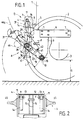
- Figure 1 of these drawings is a side view, in elevation, of a coupling device according to the invention.
- Figure 2 is a partial view, on the left with respect to Figure 1, of the framework.
- FIG. 3 is a plan view of the coupling device of FIG. 1.
- Figure 4 is a section along the line IV-IV in Figure 3.
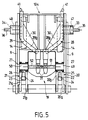
- Figure 5 is a partial front view of an alternative embodiment of the front coupling device, in the storage position.
- a front lifting device D for an agricultural tractor 1 very briefly shown including a front wheel 2 is also briefly shown.
- the ground clearance G of the tractor 1 at the front corresponds to the distance between the ground and the lowest point of the contour 3 enveloping the lower parts of the front axle, or the like.
- the device D comprises a frame 4 intended to be fixed to the chassis of the tractor 1.
- the frame 4 comprises two external sides such as 5 fixed respectively to the right and left of the tractor chassis between the front wheels.
- Each sidewall 5 comprises a rectangular plate 6 situated in a substantially vertical plane, the large dimension of which is horizontal, this plate comprising several holes 7 towards its front and rear ends for fixing to the chassis in an area located above the wheel axle 2.
- a console 8 projects upwards at the front of the plate 6; this console 8 is constituted in particular by a vertical sheet substantially coplanar with the plate 6, welded to this plate.
- the console 8 comprises a stretcher 9 extending downwards and the lower end 10 of which is situated at a distance from the ground equal to or greater than the distance G.
- the console 8 also comprises an upright 11 extending at one level higher than plate 6, towards the front.
- a central part 12 of the framework provides a rigid connection between the upper parts of the uprights 11.
- gussets 13 are fixed, in particular by welding, at a reduced distance from the uprights 11.
- a hole is provided in the upright 11 and the neighboring gusset 13 to serve as support for an axis h used for an articulated fixing of a hydraulic cylinder 14 constituting a lifting means, on each side.
- plates 15 On either side of the mediator plane of the central part 12 are provided plates 15 having opposite holes to serve as support for a pin 16 used to attach a third point bar such as the bar 17 shown in Figure 7 .
- the frame 4 is equipped, in the lower part, with lower attachment means A articulated around a transverse axis 18 carried by bearings provided in the vicinity of the lower end 10 of the stretchers 9. It thus appears that the lower point of attachment of the means A does not cause a reduction in the ground clearance G of the tractor, nor interference with a front PTO F.
- the position in a horizontal plane of the axis of rotation 18 of the stretchers is chosen so that the lever arm L defined relative to the position of the anchoring point of the jacks 14 is sufficient for the diameter of the cylinder of the jacks 14 remains compatible with the place necessary to introduce and extract the pin 16 for hooking the third point.
- the attachment means A comprise a primary lower frame 19 articulated, at its rear part, on the transverse axis 18.
- the frame 19 is provided, towards the front, with two lateral longitudinal extensions 20, 21.
- Each lateral extension comprises two members 20a, 20b, 21a, 21b separated by a space in which is received a connecting member such as a ball 22, 23 mounted at the end of the rod of each jack 14 for lifting.
- the ball 22, 23 is linked to the corresponding extension 20, 21, by an axis passing through this yoke and received, at its ends, in holes 24, provided in each member.
- a transverse bearing 25, 26 constituted by a tubular sleeve with an axis transverse parallel to the articulation axis 18 of the frame 19.
- This sleeve 25, 26 is fixed, at 27, to these members, in particular by welding.
- the open bearings 25, 26 make it possible to easily accommodate wear rings facilitating maintenance.
- the lower attachment means A comprise two forearms 28, 29 associated respectively with each lateral extension 20, 21.
- Each forearm is bent so that its front part deviates from the middle central direction, the concavity of the arm being turned outwards. This makes it possible to obtain, between the front ends of the forearms, a distance in accordance with the coupling standards.
- a stiffening web 30, for example welded, is provided in the concavity of each arm. At the front end of each forearm is fixed, by welding, either a hand 31 (FIG.
- a hinge pin 33, 34 is fixed on the internal face of the respective forearms 28, 29, in a direction orthogonal to the forearm.
- This axis 33, 34 has an outside diameter equal, apart from the operating clearance, to that of the bore of the bearing 25, 26, corresponding, so as to be able to be quickly inserted from the outside into the bearing, and to be disassembled without tools.
- Each axis 33, 34 has an extension of small diameter 35, 36, coaxial, intended to be in the space between the extensions 20, 21 of the frame, when the forearm is mounted.
- Each extension 35, 36 is provided, at its inner end, with a stop means constituted for example by a diametral bore 37 suitable for receiving a pin 37 a which, combined with a spacer 38 engaged on the extension 35 and bearing against the inner face of the bearing 25 or 26, allows transversely blocking the corresponding forearm relative to the frame 19, while leaving freedom of rotation to this forearm around the axis of the bearing.
- extensions 35, 36 allow the attachment of a mass carrier illustrated in FIGS. 6 and 7.
- the length of these extensions 35, 36 is sufficient to ensure satisfactory attachment, but is not too great. so that a free space remains between the internal ends opposite the extensions 35, 36 to allow the passage of a transmission from the front PTO F of the tractor.
- Each forearm 28, 29 extends rearwardly beyond its hinge axis 35, 36 along a branch 28a, 29a.
- the rear end of each branch 28a, 29a comes to bear under a stop 39, 40.
- stops 39, 40 may be constituted by thick plates fixed under the frame 19, in particular by welding, and projecting laterally from the outline of this frame, above the rear ends of the forearms. During the lifting movement of the frame 19, if a load is attached to the end of the forearms 28, 29, the latter are locked in rotation by the stops 39 and 40. On the other hand, the forearms 28, 29 , can be folded up, the rear end of these forearms then deviating from the stops 39, 40.
- the forearms 28, 29 are independent and can pivot in a different manner, which allows a tool, carried by these arms, to perform a rotational movement around a plurality of longitudinal axes, for free flotation ensuring relief monitoring.
- Each forearm has, towards its rear end, a peak 41 directed upwards, substantially orthogonal to the longitudinal direction of the forearm.
- This piton 41 constituted for example by a piece of cylindrical rod, is suitable for passing through an elongated opening 42 provided in the corresponding stop 39, 40.
- the piton 41 comprises, towards its upper end, a stop means advantageously constituted by the combination of a diametral hole 43 and a pin 43 a , engaged in this hole, to block or limit the possible oscillation of the forearm relative to the frame 19.
- the adjustment is obtained by threading on the stud 41, washers 44.
- the arm has no freedom of oscillation.
- the forearm retains a certain freedom of oscillation until it comes into contact with the pin 43a with the upper washer. It is also possible to place washers such as 44 below the stops 39, 40 so as to impose a forced inclination on the corresponding forearm.
- the framework 4 comprises, in the upper part, locking means V of the lifting device in the high storage position, when this device is not used.
- the locking position illustrated in dashed lines in FIG. 1 is obtained by combination of the movement of the lower frame 19 upwards and the forearms 28 folded back, relative to the frame 19, upwards after removal of any pins provided on the pegs 41.
- the locking means V comprise in lateral projection on each side of the frame 4, in the upper part, a stud 45 rigidly fixed on the frame.
- This pin 45 can be either equipped with a ball used for hanging the tools and on which the self-locking hand 31 is hooked, or engaged in the bore of the ball joint hand 32, when the jacks 14 are in the maximum lifting position and that the corresponding forearm is tilted up.
- the assembly is designed so that in this locking position, as visible in FIG. 1, the forearm 28, 29 is substantially vertical and constitutes a shield.
- the angle s formed between the axis of the jack 14 and the mean direction of the forearm 29 locked in the high position is relatively low, less than 30 °. If the operator inadvertently controls the output of the rod of the jack 14, the forearm works essentially in traction; the locking is sufficient to withstand the force generated by the jacks 14.
- the hydraulic distributor used for the operation of the jacks 14 can be released, after disconnecting the hydraulic jacks for connecting the jacks, for another use.
- the assembly is designed so that in the storage position shown in FIG. 1, the lifting device does not interfere with a front loader mounted at the front of the tractor, and of which only the element located furthest back , namely a crosspiece 46, is shown.
- the portion of curve 47 represents part of the trajectory of the cross member 46 during movements of the front loader, this curve 47 constituting in a way the limit with which the lifting device must not interfere to allow the movements of the front loader to be free.
- the cylinders 14 can work in double effect.
- the forearms 28, 29 extend the lateral extensions and the pins 41 are engaged in the openings 42.
- the forearms can be immobilized in rotation relative to the frame 19 by a set of washers 44 of sufficient thickness, or can retain a certain freedom in oscillation allowing monitoring of the relief.
- the movements of raising or lowering of the tool are controlled by the jacks 14.
- the user controls, from the tractor cabin, the extreme high position of the frame 19 by bringing the rod of the cylinders 14 in the corresponding cylinders.
- the operator can then, on the ground, successively unlock each peak 41 and tilt the corresponding forearm upwards until it is locked on a stud 45, in a substantially vertical position.
- front ends 28 b , 29 b bent towards the outside of the forearms 28, 29 make it possible to substantially reduce the transverse dimension of the frame 19 while retaining, at the level of the attachment hands 31, 32, the width usual.
- the bent portions 28 b , 29 b are relatively forward and the risk of interference with the wheels such as 2 of the tractor, during a turning, are nonexistent.
- the bent parts 28 b , 29 b of the forearms may be able to interfere with the steered wheels if the arms remain outside the framework 4 as for the embodiment of Figures 1 to 4.
- Auxiliary axes 49, 50 are normally housed in these bearings 47, 48. These axes have coaxial extensions 51, 52, of reduced diameter, equal to that of the extensions 35, 36. When the lifting device is in the working position, the auxiliary axes 49, 50 are carried by the bearings 47, 48 and the extensions 51, 52 project outwards.
- the axes 49, 50 have been extracted from the bearings 47, 48 to be mounted in the bearings 25, 26.
- the extensions 51, 52 are longer than the extensions 35, 36 so that when the axes 49, 50 are mounted in the bearings 25, 26 in place of the axes 33, 34, the inner ends of the extensions 51, 52 are close to each other without being in contact.
- the lower frame 19 and the forearms are identical to those described with reference to the previous figures.
- the operator places the forearm 28 inside the framework 104 by engaging the axis 33 in the bearing 47, the end of the forearm 28 provided with the hand 31 being directed downwards (see figure 5).
- the hands of the forearms are close to each other.
- the operator then controls the lifting of the frame 19 in the extreme high position.
- the bearings 25 and 26 are thus brought up to the height of the hands of the forearms 28, 29.
- the operator introduces into the bearings 25, 26 in the high position, the auxiliary axes 49, 50 with their extensions 51, 52 facing the longitudinal mean plane of the frame.
Abstract
Description
L'invention est relative à un dispositif de relevage avant, pour tracteur agricole ou analogue, permettant d'atteler un outil à l'avant du tracteur en vue de le soulever et/ou de l'abaisser, ce dispositif étant du genre de ceux qui comprennent une ossature destinée à être fixée sur le châssis du tracteur, ladite ossature étant équipée, en partie basse, de moyens d'attache inférieurs s'étendant vers l'avant, articulés autour d'un axe transversal, et aux extrémités desquels peuvent venir s'accrocher les deux points bas d'accrochage d'un outil, et, en partie haute, d'un moyen d'attache supérieur médian, pour une liaison avec un troisième point d'accrochage de l'outil, et des moyens de relevage, en particulier hydrauliques, prévus entre l'ossature et les moyens d'attache inférieurs pour assurer les mouvements de montée ou de descente, les moyens d'attache inférieurs comprenant, d'une part, un bâti inférieur primaire articulé, à sa partie arrière, sur un axe transversal porté par l'ossature, et muni vers l'avant de deux extensions longitudinales latérales dans chacune desquelles est prévue un palier transversal, et, d'autre part, un avant-bras associé à chaque extension longitudinale et articulé autour d'un axe porté par le susdit palier, l'ensemble étant tel qu'en position de travail l'avant-bras prolonge l'extension latérale vers l'avant, ledit avant-bras s'étendant, vers l'arrière, au-delà de son axe d'articulation, cet avant-bras, lorsqu'il est libre de toute charge, pouvant être replié vers le haut, relativement à l'ossature, pour une position de stockage, un verrouillage fixe des avant-bras en position haute étant prévu.The invention relates to a front lifting device, for agricultural tractor or the like, making it possible to couple a tool to the front of the tractor in order to raise and / or lower it, this device being of the type of those which comprise a frame intended to be fixed to the chassis of the tractor, said frame being equipped, at the bottom, with lower attachment means extending forward, articulated around a transverse axis, and at the ends of which can hook the two low points of attachment of a tool, and, in the upper part, of a middle upper attachment means, for a connection with a third point of attachment of the tool, and means lifting, in particular hydraulic, provided between the frame and the lower attachment means for ensuring the movements of ascent or descent, the lower attachment means comprising, on the one hand, a primary articulated lower frame, at its rear part, on a tran axis sversal carried by the frame, and provided towards the front with two lateral longitudinal extensions in each of which is provided a transverse bearing, and, on the other hand, an forearm associated with each longitudinal extension and articulated around an axis carried by the above bearing, the assembly being such that in the working position the forearm extends the lateral extension towards the front, said forearm extending, towards the rear, beyond its hinge pin, this forearm, when free of any load, which can be folded up, relative to the frame, for a storage position, a fixed locking of the forearms in the high position being provided .
Un dispositif de ce type est connu, notamment d'après EP-A-0 182 091.A device of this type is known, in particular from EP-A-0 182 091.
On sait qu'un tel dispositif de relevage avant permet l'emploi simultané d'au moins deux outils avec un tracteur agricole, à savoir un outil poussé et un outil tracté. Toutefois, le développement des relevages avant se heurte à plusieurs difficultés qu'il convient de prendre en compte si l'on veut accroître leur diffusion.It is known that such a front lifting device allows the simultaneous use of at least two tools with an agricultural tractor, namely a pushed tool and a towed tool. However, the development of front linkages faces several difficulties which should be taken into account if we want to increase their distribution.
Un problème se pose lorsque le dispositif de relevage avant n'est pas utilisé.A problem arises when the front lift device is not used.
Selon EP-A-0 182 091 les avant-bras peuvent être placés et maintenus en position relevés, par les moyens de relevage, pour réduire autant que possible l'encombrement frontal du dispositif de relevage avant. Toutefois, en cas de manoeuvre erronée des moyens de relevage par l'opérateur, ce dernier peut provoquer la descente des avant-bras alors qu'une telle descente n'est pas souhaitée et peut être gênante, ou même dangereuse.According to EP-A-0 182 091 the forearms can be placed and held in the raised position, by the lifting means, to reduce as much as possible the front dimensions of the front lifting device. However, in the event of erroneous operation of the means of lifting by the operator, the latter can cause the lowering of the forearms when such a lowering is not desired and can be annoying, or even dangerous.
L'invention vise, notamment, à fournir un dispositif de relevage qui permette d'éviter des conséquences fâcheuses en cas d'actionnement des moyens de relevage, alors que les avant-bras sont relevés et doivent le rester.The invention aims, in particular, to provide a lifting device which makes it possible to avoid unfortunate consequences in the event of actuation of the lifting means, while the forearms are raised and must remain so.
Le dispositif de relevage peut aussi constituer une gêne, en particulier si l'opérateur souhaite monter à l'avant de son tracteur un chargeur frontal. Dans un tel cas, l'opérateur peut avoir à démonter au préalable le dispositif de relevage avant puis installer son chargeur frontal.The lifting device can also be a nuisance, in particular if the operator wishes to mount a front loader at the front of his tractor. In such a case, the operator may have to dismantle the front lifting device beforehand and then install his front loader.
Cette opération de démontage du relevage avant, pendant la période où il n'est pas utilisé, constitue une contrainte gênante et un frein à l'expansion des dispositifs de relevage avant.This dismantling operation of the front linkage, during the period when it is not in use, constitutes an annoying constraint and a brake on the expansion of the front linkage devices.
De plus, certains travaux doivent être réalisés alternativement et sont totalement incompatibles avec les opérations de montage-démontage répétées.In addition, certain works must be carried out alternately and are completely incompatible with repeated assembly-disassembly operations.
EP-A-0 274 853 décrit, certes, un dispositif de relevage permettant une compatibilité avec un chargeur frontal. Cependant, la conception de ce dispositif de relevage limite la garde au sol et le rayon de braquage au travail, car, pour un repli de chaque côté du tracteur, il faut un relevage suffisamment large qui interfère avec les roues lorsqu'elles sont braquées.EP-A-0 274 853 describes, of course, a lifting device allowing compatibility with a front loader. However, the design of this lifting device limits the ground clearance and the turning radius at work, because, for a fall on each side of the tractor, a sufficiently large lift is required which interferes with the wheels when they are turned.
L'invention a pour but, surtout, de fournir un dispositif de relevage avant qui ne présente plus ou à un degré moindre les inconvénients rappelés ci-dessus. On souhaite que lorsque ce dispositif de relevage avant est en position de stockage, sur le tracteur, il ne puisse être mis en position de travail si les moyens de relevage sont actionnés par erreur ou accidentellement. On souhaite en outre que ce dispositif soit non seulement compatible avec un chargeur frontal mais aussi qu'il ne limite pas la maniabilité du tracteur. On souhaite également qu'un tel dispositif de relevage avant ne constitue pas un obstacle au passage d'une transmission de mouvement à partir de la prise de force avant du tracteur.The invention aims, above all, to provide a front lifting device which no longer has or to a lesser degree the drawbacks mentioned above. It is desired that when this front lifting device is in the storage position on the tractor, it cannot be put into the working position if the lifting means are actuated by error or accidentally. It is further desired that this device is not only compatible with a front loader but also that it does not limit the maneuverability of the tractor. It is also desired that such a front lifting device does not constitute an obstacle to the passage of a movement transmission from the front PTO of the tractor.
Il serait avantageux que le dispositif de relevage avant permette une flottation libre de l'outil si on le souhaite, ainsi qu'un réglage de l'inclinaison de l'outil, ou un verrouillage complet.It would be advantageous if the front lifting device allowed free flotation of the tool if desired, as well as adjustment of the inclination of the tool, or complete locking.
La mise en place et le réglage du dispositif de relevage avant doivent être aussi simples et rapides que possible.The installation and adjustment of the front lifting device must be as simple and quick as possible.
Selon l'invention, un dispositif de relevage avant, pour tracteur agricole ou analogue, permettant d'atteler un outil à l'avant du tracteur en vue de le soulever et de l'abaisser, du genre défini précédemment, est caractérisé par le fait que les moyens de relevage sont reliés au bâti, inférieur et à l'ossature, que les deux avant-bras sont indépendants l'un de l'autre, que chaque avant-bras vient en appui par sa partie arrière, lorsqu'il est en position de travail, sous une butée solidaire du bâti de manière à se bloquer lors du relevage du bâti et du soulèvement d'une charge, et que le verrouillage fixe des avant-bras, en position haute du bâti permet d'empêcher un mouvement du bâti même si l'opérateur commande, par mégarde, les moyens de relevage.According to the invention, a front lifting device, for agricultural tractor or the like, making it possible to couple a tool to the front of the tractor in order to raise and lower it, of the kind defined above, is characterized by the fact that the lifting means are connected to the frame, lower and to the framework, that the two forearms are independent of each other, that each forearm comes to bear by its rear part, when it is in the working position, under a stop integral with the frame so as to lock during lifting of the frame and lifting of a load, and that the fixed locking of the forearms, in the high position of the frame makes it possible to prevent movement of the frame even if the operator inadvertently controls the lifting means.
Avantageusement, l'ossature comporte des moyens de verrouillage des avant-bras du bâti en position haute, par combinaison du mouvement du bâti inférieur mobile primaire, vers le haut, repli des avant-bras relativement au bâti vers le haut, et accrochage des avant-bras sur un organe de support et de verrouillage prévu sur l'ossature.Advantageously, the framework comprises means for locking the forearms of the frame in the high position, by combination of the movement of the primary movable lower frame, upwards, folding of the forearms relative to the frame upwards, and hooking of the fronts. -arm on a support and locking member provided on the frame.
De préférence, l'organe de support et de verrouillage est constitué par un têton sur lequel vient s'accrocher l'extrémité des avant-bras.Preferably, the support and locking member is constituted by a pin on which the end of the forearms is hooked.
En variante, pour réaliser le verrouillage du dispositif, lorsqu'il n'est pas utilisé, l'ossature peut comporter, en partie haute, des paliers semblables à ceux portés par les extensions du bâti inférieur, ces paliers étant munis, lorsque l'ensemble est en position de travail, d'axes auxiliaires semblables à ceux des avant-bras, munis de prolongements plus longs que ceux des avant-bras, l'ensemble étant tel que pour le verrouillage des avant-bras, en position haute du bâti inférieur, les axes auxiliaires des paliers de l'ossature sont retirés de ces paliers, tandis que les avant-bras sont démontés des extensions et retournés de manière à être placés à l'intérieur de l'ossature avec leurs axes reçus dans les paliers hauts de l'ossature, tandis que les axes auxiliaires sont montés dans les paliers des extensions latérales avec leurs prolongements tournés vers l'intérieur, l'ensemble étant tel que les extrémités des avant-bras viennent s'accrocher sur les prolongements desdits axes auxiliaires lorsque le bâti inférieur est relevé.Alternatively, to achieve the locking of the device, when it is not in use, the framework may include, in the upper part, bearings similar to those carried by the extensions of the lower frame, these bearings being provided, when the assembly is in working position, auxiliary axes similar to those of the forearms, provided with longer extensions than those of the forearms, the assembly being such as for locking the forearms, in the raised position of the frame lower, the auxiliary axes of the bearings of the framework are removed from these bearings, while the forearms are dismounted from the extensions and returned so as to be placed inside the framework with their axes received in the high bearings of the framework, while the axes auxiliaries are mounted in the bearings of the lateral extensions with their extensions facing inwards, the assembly being such that the ends of the forearms are hooked onto the extensions of said auxiliary axes when the lower frame is raised.
Chaque extension latérale peut comprendre deux membrures séparées par un espace dans lequel est reçu un organe de liaison constituant une extrémité des moyens de relevage, cet organe étant lié à l'extension par un axe traversant des ouvertures prévues dans les membrures, tandis que le palier prévu à l'extrémité de l'extension latérale est constitué par un manchon d'axe transversal.Each lateral extension may comprise two members separated by a space in which is received a connecting member constituting one end of the lifting means, this member being linked to the extension by an axis passing through openings provided in the members, while the bearing provided at the end of the lateral extension is constituted by a sleeve of transverse axis.
L'axe d'articulation de chaque avant-bras peut être fixé sur ce dernier de manière à pouvoir s'insérer rapidement dans le palier de l'extension correspondante, sans outillage, le bras étant situé à l'extérieur de l'extension.The articulation axis of each forearm can be fixed on the latter so as to be able to be inserted quickly into the bearing of the corresponding extension, without tools, the arm being located outside the extension.
L'axe fixé sur chaque avant-bras peut comporter un prolongement de diamètre plus faible destiné à se trouver entre les extensions du bâti lorsque le bras est monté, ce prolongement pouvant servir le cas échéant à l'accrochage d'accessoires, notamment à l'accrochage d'un porte-masse.The axis fixed on each forearm may include a smaller diameter extension intended to be located between the extensions of the frame when the arm is mounted, this extension being able to be used where appropriate for the attachment of accessories, in particular to the '' attachment of a mass carrier.
Avantageusement, le prolongement est muni de moyens d'arrêt de l'axe relativement au palier, avec interposition éventuelle de rondelles, suivant la direction axiale de ce palier.Advantageously, the extension is provided with means for stopping the axis relative to the bearing, with possible interposition of washers, in the axial direction of this bearing.
Le prolongement de chaque axe a une longueur réduite de sorte qu'un espace suffisant existe entre les extrémités en regard des prolongements, lorsque les deux avant-bras sont montés, pour le passage d'une transmission mécanique à partir de la prise de force avant du tracteur.The extension of each axis has a reduced length so that there is sufficient space between the ends opposite the extensions, when the two forearms are mounted, for the passage of a mechanical transmission from the front PTO of the tractor.
Chaque avant-bras peut comporter, vers son extrémité arrière, un piton orienté sensiblement orthogonalement à la direction longitudinale de l'avant-bras et situé au-delà de l'axe d'articulation de l'avant-bras, ce piton étant propre à traverser une ouverture prévue dans une butée solidaire du bâti, située au-dessus de la partie arrière de l' avant-bras.Each forearm may comprise, towards its rear end, a piton oriented substantially orthogonally to the longitudinal direction of the forearm and situated beyond the axis of articulation of the forearm, this piton being clean through an opening provided in a stop integral with the frame, located above the rear part of the forearm.
Le piton reçoit un jeu de rondelles d'épaisseur variable et est muni de moyens d'arrêt de l'oscillation de l' avant-bras, de manière à permettre divers réglages possibles pour cet avant-bras, à savoir oscillant, fixe, ou à inclinaison forcée.The piton receives a set of washers of variable thickness and is provided with means for stopping the oscillation of the forearm, so as to allow various possible adjustments for this forearm, namely oscillating, fixed, or forced tilt.
Les moyens d'arrêt de l'axe d'un avant-bras, relativement au palier peuvent être agencés pour permettre un déverrouillage rapide de l'avant-bras en vue d'un coulissement transversal de sorte que lorsque l' avant-bras est équipé à son extrémité d'une rotule à alésage, il soit possible, par coulissement transversal, d'amener l'alésage de cette rotule en face d'un têton porté par l'ossature, en position haute de stockage, et par un coulissement en sens inverse, d'engager le têton dans l'alésage de ladite rotule pour assurer le verrouillage en position de stockage.The means for stopping the axis of a forearm, relative to the bearing, can be arranged to allow rapid unlocking of the forearm for transverse sliding so that when the forearm is equipped at its end with a ball joint with bore, it is possible, by transverse sliding, to bring the bore of this ball joint in front of a stud carried by the frame, in the high storage position, and by sliding in the opposite direction, to engage the pin in the bore of said ball to ensure locking in the storage position.
Le dispositif peut être agencé de telle sorte que les avant-bras repliés, en position de stockage, présentent une face avant sensiblement verticale ayant fonction de bouclier.The device can be arranged so that the folded forearms, in the storage position, have a substantially vertical front face having the function of a shield.
L'invention consiste, mises à part les dispositions exposées ci-dessus, en un certain nombre d'autres dispositions dont il sera plus explicitement question ci-après à propos d'exemples de réalisation décrits avec référence aux dessins ci-annexés, mais qui ne sont nullement limitatifs.The invention consists, apart from the arrangements set out above, of a certain number of other arrangements which will be more explicitly discussed below in connection with embodiments described with reference to the attached drawings, but which are in no way limiting.
La figure 1, de ces dessins, est une vue de côté, en élévation, d'un dispositif d'attelage selon l'invention.Figure 1 of these drawings is a side view, in elevation, of a coupling device according to the invention.
La figure 2 est une vue partielle, de gauche par rapport à la figure 1, de l'ossature.Figure 2 is a partial view, on the left with respect to Figure 1, of the framework.
La figure 3 est une vue en plan du dispositif d'attelage de la figure 1.FIG. 3 is a plan view of the coupling device of FIG. 1.
La figure 4 est une coupe suivant la ligne IV-IV figure 3.Figure 4 is a section along the line IV-IV in Figure 3.
La figure 5, enfin, est une vue partielle, de face d'une variante de réalisation du dispositif d'attelage avant, en position de stockage.Figure 5, finally, is a partial front view of an alternative embodiment of the front coupling device, in the storage position.
En se reportant aux dessins, plus particulièrement aux figures 1 à 3, on peut voir un dispositif de relevage avant D pour un tracteur agricole 1 très sommairement représenté, dont une roue avant 2 est également sommairement représentée. La garde au sol G du tracteur 1 à l'avant correspond à la distance entre le sol et le point le plus bas du contour 3 enveloppant les parties inférieures de l'essieu avant, ou analogue.Referring to the drawings, more particularly to Figures 1 to 3, one can see a front lifting device D for an
Le dispositif D comprend une ossature 4 destinée à être fixée sur le châssis du tracteur 1. L'ossature 4 comprend deux flancs extérieurs tels que 5 fixés respectivement à droite et à gauche du châssis du tracteur entre les roues avant. Chaque flanc 5 comprend une plaque rectangulaire 6 située dans un plan sensiblement vertical, dont la grande dimension est horizontale, cette plaque comportant plusieurs trous 7 vers ses extrémités avant et arrière pour la fixation sur le châssis dans une zone située au-dessus de l'axe de la roue 2. Une console 8 fait saillie vers le haut à l'avant de la plaque 6 ; cette console 8 est constituée notamment par une tôle verticale sensiblement coplanaire à la plaque 6, soudée à cette plaque. La console 8 comporte un brancard 9 s'étendant vers le bas et dont l'extrémité inférieure 10 est située à une distance du sol égale ou supérieure à la distance G. La console 8 comporte en outre un montant 11 s'étendant à un niveau supérieur à la plaque 6, vers l'avant.The device D comprises a
Une partie centrale 12 de l'ossature assure une liaison rigide entre les parties hautes des montants 11. Comme visible sur la figure 2, vers les extrémités latérales de la partie centrale, des goussets 13 sont fixés, notamment par soudure, à distance réduite des montants 11. Un trou est prévu dans le montant 11 et le gousset 13 voisin pour servir de support à un axe h servant à une fixation articulée d'un vérin hydraulique 14 constituant un moyen de relevage, de chaque côté. De part et d'autre du plan médiateur de la partie centrale 12 sont prévues des plaquettes 15 comportant des trous en regard pour servir de support à un axe 16 servant à attacher une barre de troisième point telle que la barre 17 représentée sur la figure 7.A
L'ossature 4 est équipée, en partie basse, de moyens d'attache inférieurs A articulés autour d'un axe transversal 18 porté par des paliers prévus au voisinage de l'extrémité inférieure 10 des brancards 9. Il apparaît ainsi que le point inférieur d'accrochage des moyens A ne provoque pas de réduction de la garde au sol G du tracteur, ni d'interférence avec une prise de force avant F. Les deux points bas d'accrochage latéraux d'un outil, non représenté, viennent s'accrocher à l'avant des moyens d'attache A.The
La position dans un plan horizontal de l'axe de rotation 18 des brancards est choisie de sorte que le bras de levier L défini par rapport à la position du point d'ancrage des vérins 14 soit suffisant pour que le diamètre du cylindre des vérins 14 reste compatible avec la place nécessaire pour introduire et extraire l'axe 16 d'accrochage du troisième point.The position in a horizontal plane of the axis of
Les moyens d'attache A comprennent un bâti inférieur primaire 19 articulé, à sa partie arrière, sur l'axe transversal 18. Le bâti 19 est muni, vers l'avant, de deux extensions longitudinales latérales 20, 21. Chaque extension latérale comprend deux membrures 20a, 20b, 21a, 21b séparées par un espace dans lequel est reçue un organe de liaison tel qu'une rotule 22, 23 montée à l'extrémité de la tige de chaque vérin 14 de relevage. La rotule 22, 23 est liée à l'extension correspondante 20, 21, par un axe traversant cette chape et reçue, à ses extrémités, dans des trous 24, prévus dans chaque membrure.The attachment means A comprise a primary
En avant des trous 24, mais à distance aussi réduite que possible compte tenu de l'encombrement des rotules 22, 23 et du passage de la tige du vérin 14, est prévu un palier transversal 25, 26 constitué par un manchon tubulaire d'axe transversal parallèle à l'axe d'articulation 18 du bâti 19. Ce manchon 25, 26 est fixé, en 27, sur ces membrures, notamment par soudage. Les paliers 25, 26, ouverts permettent de loger aisément des bagues d'usure facilitant la maintenance.In front of the
Les moyens d'attache A inférieurs comprennent deux avant-bras 28,29 associés respectivement à chaque extension latérale 20, 21. Chaque avant-bras est coudé de sorte que sa partie avant s'écarte de la direction centrale moyenne, la concavité du bras étant tournée vers l'extérieur. Ceci permet d'obtenir, entre les extrémités avant des avant-bras, une distance conforme aux normes d'attelage. Un voile raidisseur 30, par exemple soudé, est prévu dans la concavité de chaque bras. A l'extrémité avant de chaque avant-bras est fixée, par soudure, soit une main 31 (figure 1) à verrouillage automatique, ouverte vers le haut et permettant un encliquetage d'un axe par un simple mouvement vertical de descente, soit un dispositif 32 à rotule à alésage fermé dans laquelle l'engagement d'un arbre doit s'effectuer suivant la direction axiale de l'alésage de la rotule.The lower attachment means A comprise two
Un axe d'articulation 33, 34 est fixé sur la face interne des avant-bras respectifs 28, 29, suivant une direction orthogonale à l'avant-bras. Cet axe 33, 34 a un diamètre extérieur égal, au jeu de fonctionnement près, à celui de l'alésage du palier 25, 26, correspondant, de manière à pouvoir être inséré rapidement depuis l'extérieur, dans le palier, et en être démonté, sans outillage.A
Chaque axe 33, 34 comporte un prolongement de faible diamètre 35, 36, coaxial, destiné à se trouver dans l'espace compris entre les extensions 20, 21 du bâti, lorsque l'avant-bras est monté. Chaque prolongement 35, 36 est muni, à son extrémité intérieure, d'un moyen d'arrêt constitué par exemple par un alésage diamétral 37 propre à recevoir une goupille 37a qui, combinée avec une entretoise 38 engagée sur le prolongement 35 et prenant appui contre la face intérieure du palier 25 ou 26, permet de bloquer transversalement l'avant-bras correspondant relativement au bâti 19, tout en laissant une liberté de rotation à cet avant-bras autour de l'axe du palier.Each
Comme expliqué plus loin, les prolongements 35, 36 permettent la fixation d'un porte-masse illustré sur les figures 6 et 7. La longueur de ces prolongements 35, 36 est suffisante pour assurer un accrochage satisfaisant, mais n'est pas trop importante pour qu'un espace libre subsiste entre les extrémités internes en regard des prolongements 35, 36 pour permettre le passage d'une transmission à partir de la prise de force avant F du tracteur.As explained below, the
Chaque avant-bras 28, 29 s'étend, vers l'arrière, au-delà de son axe d'articulation 35, 36 selon une branche 28a, 29a. L'extrémité arrière de chaque branche 28a, 29a vient en appui sous une butée 39, 40.Each
Ces butées 39, 40 peuvent être constituées par des plaques épaisses fixées sous le bâti 19, notamment par soudage, et débordant latéralement du contour de ce bâti, au-dessus des extrémités arrière des avant-bras. Lors du mouvement de levée du bâti 19, si une charge est accrochée à l'extrémité des avant-bras 28, 29, ces derniers se trouvent bloqués en rotation par les butées 39 et 40. Par contre, les avant-bras 28, 29, peuvent être repliés vers le haut, l'extrémité arrière de ces avant-bras s'écartant alors des butées 39, 40.These stops 39, 40 may be constituted by thick plates fixed under the
Il est à noter que les avant-bras 28, 29 sont indépendants et peuvent pivoter de manière différente, ce qui permet à un outil, porté par ces bras, d'effectuer un mouvement de rotation autour d'une pluralité d'axes longitudinaux, pour une flottation libre assurant un suivi du relief.It should be noted that the
Chaque avant-bras comporte, vers son extrémité arrière, un piton 41 dirigé vers le haut, sensiblement orthogonal à la direction longitudinale de l' avant-bras. Ce piton 41, constitué par exemple par un morceau de tige cylindrique, est propre à traverser une ouverture allongée 42 prévue dans la butée correspondante 39, 40. Le piton 41 comporte, vers son extrémité haute, un moyen d'arrêt avantageusement constitué par la combinaison d'un trou diamétral 43 et d'une goupille 43a, engagée dans ce trou, pour bloquer ou limiter l'oscillation possible de l'avant-bras relativement au bâti 19.Each forearm has, towards its rear end, a
Le réglage est obtenu en enfilant sur le piton 41, des rondelles 44. Lorsque toutes les rondelles sont disposées au-dessus de la butée 40, 41 et ne laissent pas de jeu vertical entre leur face supérieure et la goupille 43a, l' avant-bras n'a aucune liberté d'oscillation. Par contre, si un jeu vertical subsiste, l' avant-bras conserve une certaine liberté d'oscillation jusqu'à venue en contact de la goupille 43a avec la rondelle supérieure. Il est également possible de placer des rondelles telles que 44 au-dessous des butées 39, 40 de manière à imposer une inclinaison forcée à l' avant-bras correspondant.The adjustment is obtained by threading on the
Comme visible sur la figure 2, l'ossature 4 comporte, en partie haute, des moyens de verrouillage V du dispositif de relevage en position haute de stockage, lorsque ce dispositif n'est pas utilisé. La position de verrouillage illustrée en traits mixtes sur la figure 1 est obtenue par combinaison du mouvement du bâti inférieur 19 vers le haut et repli des avant-bras 28, 29, relativement au bâti 19, vers le haut après retrait des goupilles éventuelles prévues sur les pitons 41. Les moyens de verrouillage V comprennent en saillie latérale de chaque côté de l'ossature 4, en partie haute, un têton 45 fixé rigidement sur l'ossature. Ce têton 45 peut être soit équipé d'une boule utilisée pour l'accrochage des outils et sur laquelle vient s'accrocher la main à verrouillage automatique 31, soit engagé dans l'alésage de la main à rotule 32, lorsque les vérins 14 sont dans la position de relevage maximum et que l' avant-bras correspondant est basculé vers le haut.As can be seen in FIG. 2, the
L'ensemble est conçu de manière que dans cette position de verrouillage, comme visible sur la figure 1, 1' avant-bras 28, 29 soit sensiblement vertical et constitue un bouclier. En outre, l'angle s formé entre l'axe du vérin 14 et la direction moyenne de l'avant-bras 29 verrouillé en position haute est relativement faible, inférieur à 30°. Si par mégarde l'opérateur commande la sortie de la tige du vérin 14, l'avant-bras travaille essentiellement en traction ; le verrouillage est suffisant pour résister à l'effort engendré par les vérins 14.The assembly is designed so that in this locking position, as visible in FIG. 1, the
Le verrouillage fixe en position haute selon l'invention permet à la fois :
- d'empêcher le bâti 19 et les avant-
bras - d'empêcher les avant-bras de tourner relativement au bâti.
- to prevent the
frame 19 and theforearms - prevent the forearms from rotating relative to the frame.
Ces deux fonctions réalisées en une seule opération permettent d'éviter des erreurs.These two functions performed in a single operation allow errors to be avoided.
Le distributeur hydraulique utilisé pour le fonctionnement des vérins 14 peut être libéré, après débranchement de prises hydrauliques de raccordement des vérins, pour un autre usage.The hydraulic distributor used for the operation of the
Si les avant-bras sont équipés de mains à rotule 32 comme illustré sur la figure 2 au lieu des mains à verrouillage automatique de la figure 4, il faut opérer de la manière suivante pour engager les têtons de verrouillage 45 dans ces rotules.If the forearms are equipped with ball-
On déverrouille les axes 33, 34 en retirant les goupilles 37a des trous 37 et, après avoir dégagé le pion 41 des ouvertures 42, on tire vers l'extérieur, sur chaque avant-bras pour l'écarter de l'extension 20, 21 correspondante. Dans ces conditions, lorsque l'on bascule le bras vers le haut, la rotule 32 se trouvera axialement déportée vers l'extérieur par rapport au têton 45 et son alésage peut être aligné sur ce têton. En repoussant l' avant-bras contre l'extension associée, on peut alors engager le têton 45 dans la rotule correspondante 32 et assurer le verrouillage en position haute du dispositif de relevage pour le stockage.Is unlocked the
L'ensemble est conçu de manière qu'en position de stockage représentée sur la figure 1, le dispositif de relevage n'interfère pas avec un chargeur frontal monté à l'avant du tracteur, et dont seul l'élément situé le plus en arrière, à savoir une traverse 46, est représenté. La portion de courbe 47 représente une partie de la trajectoire de la traverse 46 lors des mouvements du chargeur frontal, cette courbe 47 constituant en quelque sorte la limite avec laquelle ne doit pas interférer le dispositif de relevage pour laisser libres les mouvements du chargeur frontal.The assembly is designed so that in the storage position shown in FIG. 1, the lifting device does not interfere with a front loader mounted at the front of the tractor, and of which only the element located furthest back , namely a
Les vérins 14 peuvent travailler en double effet.The
Le fonctionnement et l'utilisation du dispositif de relevage résultent immédiatement des explications qui précèdent.The operation and use of the lifting device immediately result from the foregoing explanations.
Lorsque ce dispositif est en position de travail, les avant-bras 28, 29 prolongent les extensions latérales et les pitons 41 sont engagés dans les ouvertures 42. Selon le réglage adopté, les avant-bras peuvent être immobilisés en rotation relativement au bâti 19 par un jeu de rondelles 44 d'épaisseur suffisante, ou peuvent conserver une certaine liberté en oscillation permettant un suivi du relief. Les mouvements de montée ou de descente de l'outil sont commandés par les vérins 14.When this device is in the working position, the
Pour la mise en position de stockage, alors que les avant-bras ont été libérés de l'outil, l'utilisateur commande, depuis la cabine du tracteur, la mise en position haute extrême du bâti 19 en faisant entrer au maximum la tige des vérins 14 dans les cylindres correspondants.For the storage position, while the forearms have been released from the tool, the user controls, from the tractor cabin, the extreme high position of the
L'opérateur peut ensuite, au sol, déverrouiller successivement chaque piton 41 et basculer l' avant-bras correspondant vers le haut jusqu'à son verrouillage sur un têton 45, en position sensiblement verticale.The operator can then, on the ground, successively unlock each peak 41 and tilt the corresponding forearm upwards until it is locked on a
Les opérations sont facilitées par le fait qu'un seul avant-bras est à manipuler, successivement.The operations are facilitated by the fact that only one forearm is to be manipulated, successively.
On remarquera que les extrémités avant 28b, 29b coudées vers l'extérieur des avant-bras 28, 29 permettent de réduire sensiblement la dimension transversale du bâti 19 tout en conservant, au niveau des mains d'accrochage 31, 32, la largeur habituelle.It will be noted that the front ends 28 b , 29 b bent towards the outside of the
Lorsque les bras sont en position de travail, les parties coudées 28b, 29b, sont relativement en avant et le risque d'interférence avec les roues telles que 2 du tracteur, lors d'un braquage, sont inexistants.When the arms are in the working position, the
Par contre, pour certaines configurations, il est possible que dans la position relevée de stockage, les parties coudées 28b, 29b des avant-bras soient susceptibles d'interférer avec les roues directrices si les bras demeurent à l'extérieur de l'ossature 4 comme pour l'exemple de réalisation des figures 1 à 4.On the other hand, for certain configurations, it is possible that in the raised storage position, the
Pour éviter un tel problème, on prévoit, comme illustré sur la figure 5, une ossature 104, munie, en partie haute, de chaque côté, de paliers transversaux 47, 48 semblables aux paliers 25 et 26 de la figure 2, de sorte que les axes 33, 34 puissent être introduits dans ces paliers 47, 48 lorsqu'on le souhaite.To avoid such a problem, provision is made, as illustrated in FIG. 5, for a
Des axes auxiliaires 49, 50 sont normalement logés dans ces paliers 47, 48. Ces axes comportent des prolongements 51, 52 coaxiaux, de diamètre réduit, égal à celui des prolongements 35, 36. Lorsque le dispositif de relevage est en position de travail, les axes auxiliaires 49, 50 sont portés par les paliers 47,48 et les prolongements 51, 52 font saillie vers l'extérieur.
Par contre, dans la position de stockage illustrée sur la figure 5, les axes 49, 50 ont été extraits des paliers 47, 48 pour être montés dans les paliers 25, 26. Les prolongements 51, 52 sont plus longs que les prolongements 35, 36 de sorte que lorsque les axes 49, 50 sont montés dans les paliers 25, 26 à la place des axes 33, 34, les extrémités intérieures des prolongements 51, 52 sont voisines les unes des autres sans être en contact. Le bâti inférieur 19 et les avant-bras sont identiques à ceux décrits avec référence aux figures précédentes.On the other hand, in the storage position illustrated in FIG. 5, the
Lorsque l'opérateur souhaite placer le dispositif de relevage en position de stockage, il effectue le démontage des avant-bras 28, 29 relativement au bâti, en dégageant les goupilles des prolongements 35 et 36 et en extrayant les axes des paliers 25, 26.When the operator wishes to place the lifting device in the storage position, he dismantles the
L'opérateur extraie ensuite les axes 49, 50 des paliers 47 et 48 qui sont ainsi libres.The operator then extracts the
L'opérateur fait alors subir aux avant-bras 28, 29 un retournement de 180°autour d'un axe sensiblement vertical de telle sorte que la concavité de chaque avant-bras coudé soit tournée vers l'intérieur.The operator then makes the
L'opérateur place l'avant-bras 28 à l'intérieur de l'ossature 104 en engageant l'axe 33 dans le palier 47, l'extrémité de l'avant-bras 28 munie de la main 31 étant dirigée vers le bas (voir figure 5).The operator places the
L'opérateur agit de la même manière pour le bras 29 dont l'axe 34 est introduit dans le palier 48 (figure 5).The operator acts in the same way for the
Les mains des avant-bras sont voisines l'une de l'autre.The hands of the forearms are close to each other.
L'opérateur commande ensuite le relevage du bâti 19 en position haute extrême. Les paliers 25 et 26 sont ainsi amenés à la hauteur des mains des avant-bras 28, 29.The operator then controls the lifting of the
Pour verrouiller ces mains, l'opérateur introduit dans les paliers 25, 26 en position haute, les axes auxiliaires 49, 50 avec leurs prolongements 51, 52 tournés vers le plan moyen longitudinal de l'ossature.To lock these hands, the operator introduces into the
Dans le cas de mains 32 à rotule, les prolongements 51, 52 sont engagés dans les alésages de ces rotules par le mouvement de translation.In the case of
Dans le cas de mains 31 à verrouillage automatique, on peut d'abord mettre en place les axes auxiliaires 49, 50 dans les paliers relevés 25, 26 puis assurer le verrouillage des mains 31 sur le prolongement correspondant 51, 52 par un mouvement de pivotement de l'avant-bras autour du palier 49 ou 50.In the case of
Dans cette position de stockage du dispositif de relevage on retrouve tous les avantages décrits à propos des figures précédentes ; en outre l'encombrement transversal est réduit au minimum puisque les avant-bras 28, 29 se trouvent entre les parties latérales de l'ossature, de sorte que les risques d'interférence avec les roues avant du tracteur, lors d'un braquage, sont supprimés.In this storage position of the lifting device there are all the advantages described with reference to the previous figures; in addition, the transverse dimensions are reduced to a minimum since the
Claims (14)
- Front lifting device, for an agricultural tractor or the like, making it possible to hitch a tool to the front of the tractor for the purpose of raising and/or lowering it, comprising a framework (4, 104) intended to be fixed to the chassis of the tractor, the said framework being equipped, at the bottom, with lower securing means (A), extending forward articulated about a transverse spindle and at the ends of which the bottom two fastening points of a tool can be fastened, and, at the top, with a middle upper securing means (16) for connection with a third fastening point of the tool, and lifting means (14), particularly hydraulic ones, provided between the framework (4, 104) and the lower securing means in order to provide the ascending or descending movements, the lower securing means (A) comprising, on the one hand, a primary lower structure (19) articulated, at its rear part, to a transverse spindle (18) carried by the framework (4, 104), and equipped toward the front with two lateral longitudinal extensions (20, 21) in each of which is provided a transverse bearing (25, 26) and, on the other hand, a forearm (28, 29) associated with each longitudinal extension (20, 21) and articulated about a spindle (33, 34) carried by the abovementioned bearing, the assembly being such that in the working position the forearm (28, 29) extends the lateral extension forward, the said forearm extending, toward the rear, beyond its articulation spindle, it being possible for this forearm (28, 29), when it is devoid of any load, to be folded upward relative to the framework (4, 104) for a storage position, a fixed locking of the forearms (28, 29) in the top position being provided, characterized in that the lifting means (14) are joined to the lower structure (19) and to the framework (4, 104), that the two forearms (28, 29) are independent of one another, that each forearm (28, 29) comes to bear via its rear part, when it is in the working position, under a limit stop (39, 40) integral with the structure (19) so as to be blocked during the lifting of the structure and the raising of a load, and that the stationary locking of the forearms (28, 29) in the top position of the structure (19) makes it possible to prevent a movement of the structure (19) even if the operator, through carelessness, commands the lifting means (14).
- Device according to Claim 1, characterized in that the framework (4) includes means (V) for locking the forearms (28, 29) of the structure (19) in the top position, by combination of the upward movement of the primary mobile lower structure (19), folding the forearms (28, 29) upward relative to the structure, and fastening the forearms (28, 29) to a support and locking member (45) provided on the framework (4).
- Device according to Claim 2, characterized in that the support and locking member is made up of a stub (45).
- Device according to Claim 3, characterized in that the end of the forearms (28, 29) is fastened to the stub (45).
- Device according to Claim 1, characterized in that in order to lock the device when it is not in use the framework (104) includes, at the top, bearings (47, 48) similar to those (25, 26) carried by the extensions (20, 21) of the lower structure (19), these bearings (47, 48) being equipped, when the assembly is in the working position, with auxiliary spindles (49, 50) similar to those (33, 34) of the forearms, equipped with prolongations (51, 52) longer than those (35, 36) of the forearms, the assembly being such that for locking of the forearms (28, 29) in the top position of the lower structure (19), the auxiliary spindles (49, 50) of the bearings of the framework (104) are withdrawn from these bearings (47, 48), whereas the forearms (28, 29) are removed from the extensions (20, 21) and turned round so as to be placed inside the framework (104) with their spindles (33, 34) received in the top bearings (47, 48) of the framework, whereas the auxiliary spindles (49, 50) are mounted in the bearings (25, 26) of the lateral extensions (20, 21) with their prolongations (51, 52) pointed inward, the assembly being such that the ends of the forearms (28, 29) become fastened to the prolongations of the said auxiliary spindles when the lower structure (19) is lifted.
- Device according to Claim 1 or 5, characterized in that each lateral extension (20, 21) comprises two members (20a, 20b; 21a, 21b) separated by a space in which there is received a joining member (22, 23) constituting one end of the lifting means (14), this member being joined to the extension by a spindle (24) passing through openings provided in the members, whereas the bearing provided at the end of the lateral extension is made up of a bush (25, 26) of transverse axis.
- Device according to Claim 6, characterized in that the articulation spindle (33, 34) for each forearm (28, 29) is fixed to the latter so that it can be inserted rapidly into the bearing (25, 26) of the corresponding extension, without tooling, the arm (28, 29) being situated outside the extension (20, 21).
- Device according to Claim 7, characterized in that the spindle (33, 34) fixed to each forearm (28, 29) includes a prolongation (35, 36) of smaller diameter intended to be located between the extensions (20, 21) of the structure when the arm is mounted, it being possible for this prolongation to serve, if need be, for fastening accessories, particularly for fastening a weight holder.
- Device according to Claim 8, characterized in that the prolongation (35, 36) is equipped with means (37, 37a) for stopping the spindle (33, 34) relative to the bearing (25, 26), with possible interposition of washers (38), in the axial direction of this bearing.
- Device according to Claim 8, characterized in that the prolongation (35, 36) of each spindle (33, 34) has a reduced length so that there is enough space between the facing ends of the prolongations, when the two forearms (28, 29) are mounted, for the passage of a mechanical transmission from the front power take-off (F) of the tractor.
- Device according to Claim 1 or 5, characterized in that each forearm (28, 29) includes, toward its rear end, a peg (41) orientated substantially orthogonally to the longitudinal direction of the forearm and situated beyond the articulation spindle (33, 34) of the forearm, this peg (41) being capable of passing through an opening (42) provided in a limit stop (39, 40) integral with the structure (19), and situated above the rear part of the forearm.
- Device according to Claim 11, characterized in that the peg (41) receives a set of washers (44) of variable thickness and is equipped with means (43, 43a) for stopping the oscillation of the forearm so as to allow various possible settings for this forearm (28, 29), namely oscillating, fixed, or with forced inclination.
- Device according to Claim 9, characterized in that the means (37, 37a) for stopping the spindle (33, 34) of a forearm (28, 29) relative to the bearing (25, 26) are set out so as to allow rapid unlocking of the forearm for the purpose of transverse sliding so that when the forearm (28, 29) is equipped at its end with a ball joint (32) for the bore, it is possible, by transverse sliding, to bring the bore of this ball joint to face a stub (45) carried by the framework (4) in the top storage position, and, by sliding in the opposite direction, to engage the stub (45) in the bore of the said ball joint in order to provide locking in the storage position.
- Device according to one of the preceding claims, characterized in that it is set out so that the forearms (28, 29), folded up in the storage position, have a substantially vertical front face fulfilling a shield function.
Applications Claiming Priority (3)
| Application Number | Priority Date | Filing Date | Title |
|---|---|---|---|
| FR9202952A FR2688378B1 (en) | 1992-03-12 | 1992-03-12 | FRONT LIFT DEVICE, FOR AGRICULTURAL OR SIMILAR TRACTOR, AND EARTH HOLDER FOR SUCH DEVICE |
| FR9202952 | 1992-03-12 | ||
| PCT/FR1993/000228 WO1993017542A1 (en) | 1992-03-12 | 1993-03-09 | Front lifting device for tractors or similar |
Publications (2)
| Publication Number | Publication Date |
|---|---|
| EP0630179A1 EP0630179A1 (en) | 1994-12-28 |
| EP0630179B1 true EP0630179B1 (en) | 1996-05-08 |
Family
ID=9427611
Family Applications (1)
| Application Number | Title | Priority Date | Filing Date |
|---|---|---|---|
| EP93918744A Expired - Lifetime EP0630179B1 (en) | 1992-03-12 | 1993-03-09 | Front lifting device for tractors or similar |
Country Status (5)
| Country | Link |
|---|---|
| US (1) | US5542477A (en) |
| EP (1) | EP0630179B1 (en) |
| DE (1) | DE69302571T2 (en) |
| FR (1) | FR2688378B1 (en) |
| WO (1) | WO1993017542A1 (en) |
Cited By (1)
| Publication number | Priority date | Publication date | Assignee | Title |
|---|---|---|---|---|
| EP1867225A1 (en) * | 2006-06-17 | 2007-12-19 | AGCO GmbH | Implement mounting device at the front of utility vehicles |
Families Citing this family (13)
| Publication number | Priority date | Publication date | Assignee | Title |
|---|---|---|---|---|
| US5975216A (en) * | 1997-10-10 | 1999-11-02 | Tructor, Inc. | Low profile transferrable hydraulic three point hitch |
| FR2769789B1 (en) * | 1997-10-22 | 1999-12-31 | Hubert Defrancq | LIFT DEVICE, PARTICULARLY FRONT LIFT, FOR AGRICULTURAL TRACTOR OR THE LIKE |
| FR2789846B1 (en) * | 1999-02-23 | 2001-05-11 | Altec | LIFT DEVICE FOR MOUNTING AT THE FRONT OR BACK OF A PARTICULARLY AGRICULTURAL MACHINE FOR HITCHING A TOOL |
| FR2814038B1 (en) | 2000-09-15 | 2002-11-29 | Hubert Defrancq | LIFT DEVICE FOR A TRACTOR FOR ATTACHING AND DETECTING A MASS WITHOUT MANUAL INTERVENTION |
| DE10352216B3 (en) * | 2003-11-05 | 2005-07-28 | CNH Österreich GmbH | Front axle for agricultural vehicles |
| US20050167533A1 (en) * | 2004-01-05 | 2005-08-04 | Christy Jody M. | Apparatus for spreading particulate material from a work vehicle |
| FI20065658A0 (en) * | 2006-10-16 | 2006-10-16 | Lh Lift Oy | Front linkage |
| FR2937827B1 (en) | 2008-10-30 | 2013-02-15 | Hubert Defrancq | FRONT LIFTING DEVICE FOR TRACTOR. |
| US8419064B2 (en) * | 2010-04-28 | 2013-04-16 | Bridgestone Americas Tire Operations, Llc | Apparatus for adding weight to a work vehicle |
| FR3037769B1 (en) | 2015-06-23 | 2017-07-21 | Hubert Defrancq | FRONT LIFTING DEVICE FOR AGRICULTURAL EQUIPMENT AND ASSOCIATED CONTROL METHOD. |
| US10398083B2 (en) * | 2015-09-09 | 2019-09-03 | Deere & Company | Multi head windrower |
| KR101975896B1 (en) | 2016-07-08 | 2019-05-07 | (주)유미랩코리아 | Natural detergent composition comprising coffee wastes and preparation method thereof |
| EP3571908B1 (en) | 2018-05-23 | 2022-08-10 | AGCO International GmbH | Folding hitch |
Family Cites Families (23)
| Publication number | Priority date | Publication date | Assignee | Title |
|---|---|---|---|---|
| US2869654A (en) * | 1956-10-05 | 1959-01-20 | Int Harvester Co | Fast hitch for 3-point hitch |
| US3065977A (en) * | 1960-10-28 | 1962-11-27 | Int Harvester Co | Three point implement attaching hitch mechanism |
| US3145781A (en) * | 1961-09-20 | 1964-08-25 | Porsche Diesel Motorenbau G M | Tractor arrangement |
| US3561789A (en) * | 1968-11-22 | 1971-02-09 | Allis Chalmers Mfg Co | Tractor hitch |
| US3572759A (en) * | 1968-12-23 | 1971-03-30 | Allis Chalmers Mfg Co | Latch control means |
| DE2506745C3 (en) * | 1975-02-18 | 1978-06-22 | Xaver Fendt & Co, 8952 Marktoberdorf | Implement attachment device for an agriculturally usable tractor |
| NL7604307A (en) * | 1976-04-23 | 1977-10-25 | Texas Industries Inc | LIFTING DEVICE. |
| DE2848176A1 (en) * | 1978-11-07 | 1980-05-14 | Ernst Degenhart | ATTACHMENT DEVICE FOR AGRICULTURAL TRACTORS |
| US4216975A (en) * | 1978-12-11 | 1980-08-12 | Deere & Company | Tractor hitch |
| GB2046683B (en) * | 1979-03-21 | 1984-03-28 | Lely Nv C Van Der | Tractor |
| DE3177077D1 (en) * | 1981-04-22 | 1989-08-17 | Deere & Co | Front implement hitch device for a front covered vehicle for use in agriculture and/or the building industry, in particular for a farming tractor |
| FR2511574A1 (en) * | 1981-08-24 | 1983-02-25 | Chaigne Guy | Farm tractor implement mounting - comprises intermediate frame tilted by double acting ram and with triangular hitch |
| DE3314684A1 (en) * | 1983-04-22 | 1984-10-25 | Klöckner-Humboldt-Deutz AG, 5000 Köln | DEVICE FOR SELECTIVELY CONNECTING AND UNCOUPLING AN ADDITIONAL WEIGHT LOADING THE FRONT SIDE OF AN ACTRACTOR |
| US4519623A (en) * | 1983-05-09 | 1985-05-28 | Orthman Manufacturing, Inc. | Tractor front end hitch |
| US4542913A (en) * | 1984-07-26 | 1985-09-24 | Deere & Company | Pick-up type drawbar assembly |
| DE3439048C2 (en) * | 1984-10-25 | 1986-09-11 | Deere & Co., Moline, Ill., US, Niederlassung Deere & Co. European Office, 6800 Mannheim | Power lift for a lifting device |
| DE3442557C2 (en) * | 1984-11-22 | 1986-12-11 | Deere & Co., Moline, Ill., US, Niederlassung Deere & Co. European Office, 6800 Mannheim | Connection and coupling device for front attachment to a work vehicle |
| DE3512428A1 (en) * | 1985-04-04 | 1986-10-16 | Deere & Co., Moline, Ill., US, Niederlassung Deere & Co. European Office, 6800 Mannheim | LENGTH VARIABLE LIFTING STRUT |
| JPS63148905A (en) * | 1986-12-13 | 1988-06-21 | 株式会社クボタ | Hitch apparatus of tractor and working machine |
| EP0274853A1 (en) * | 1986-12-22 | 1988-07-20 | J.I. Case GmbH | Apparatus for the frontal connection of equipment to agriculturally usable motor vehicles, in particular farming tractors |
| DE3801895A1 (en) * | 1988-01-23 | 1989-08-03 | Fendt & Co Xaver | Device on the front end of a farm tractor for raising an additional weight carrier into a transportation position |
| FR2628284B1 (en) * | 1988-03-08 | 1990-12-07 | Defrancq Hubert | HITCHING DEVICE FOR A TOOL, IN PARTICULAR AN AGRICULTURAL TOOL, TO BE CARRIED BY A TRACTOR |
| US5029650A (en) * | 1989-10-20 | 1991-07-09 | Sukup Manufacturing Company | Adjustable quick attaching hitch coupler |
-
1992
- 1992-03-12 FR FR9202952A patent/FR2688378B1/en not_active Expired - Lifetime
-
1993
- 1993-03-09 WO PCT/FR1993/000228 patent/WO1993017542A1/en active IP Right Grant
- 1993-03-09 EP EP93918744A patent/EP0630179B1/en not_active Expired - Lifetime
- 1993-03-09 US US08/295,862 patent/US5542477A/en not_active Expired - Lifetime
- 1993-03-09 DE DE69302571T patent/DE69302571T2/en not_active Expired - Fee Related
Cited By (1)
| Publication number | Priority date | Publication date | Assignee | Title |
|---|---|---|---|---|
| EP1867225A1 (en) * | 2006-06-17 | 2007-12-19 | AGCO GmbH | Implement mounting device at the front of utility vehicles |
Also Published As
| Publication number | Publication date |
|---|---|
| FR2688378B1 (en) | 1996-09-06 |
| DE69302571D1 (en) | 1996-06-13 |
| FR2688378A1 (en) | 1993-09-17 |
| WO1993017542A1 (en) | 1993-09-16 |
| DE69302571T2 (en) | 1996-12-19 |
| US5542477A (en) | 1996-08-06 |
| EP0630179A1 (en) | 1994-12-28 |
Similar Documents
| Publication | Publication Date | Title |
|---|---|---|
| EP0630179B1 (en) | Front lifting device for tractors or similar | |
| EP0178239B2 (en) | Method to transform a harvesting machine from a working position into a transport position, and harvesting machine using this method | |
| EP1774106B1 (en) | Device for coupling a loader to a tractor | |
| EP0454602B1 (en) | Haymaking machine having several rotors | |
| FR2619986A1 (en) | MECHANISM FOR CONNECTING A WORKING TOOL TO A TRACTOR | |
| EP0382666A1 (en) | Mower with release safety device | |
| EP0511922B1 (en) | Mowing machine with pivoting hitch structure | |
| EP0300937B1 (en) | Haymaking machine equipped with several pivoting raking wheels in order to be folded up for transport or storage | |
| FR2769789A1 (en) | LIFT DEVICE, PARTICULARLY FRONT LIFT, FOR AGRICULTURAL TRACTOR OR THE LIKE | |
| EP1607363A2 (en) | Crane with a telescopic boom | |
| EP1243464A1 (en) | Load handling apparatus and vehicle including such apparatus | |
| EP0012145B1 (en) | Device with articulated arms for manoeuvring a truck container | |
| EP0064925A1 (en) | Locking device for a spare wheel holder mounted under a vehicle floor | |
| EP0426588B1 (en) | Improvement for agricultural machines especially for haymaking machines | |
| WO2002021898A1 (en) | Lifting device for tractor for coupling and uncoupling a weight without manual control | |
| EP0185826B1 (en) | Elevator device for agricultural tractor loaders | |
| EP1111986B1 (en) | Running device for farm machine | |
| CA2478127A1 (en) | Agricultural machine which can be hitched to the hitch bar of a tractor vehicle | |
| FR2595305A1 (en) | Device for raising at least one rear tractor wheel | |
| FR2575027A1 (en) | Coupling device for a front loader of a tractor | |
| FR3024740A1 (en) | DEVICE FOR QUICKLY ASSEMBLING A TOOL ON THE ARM OF A MACHINE | |
| EP0616098A1 (en) | Scaffolding platform element | |
| FR2781383A1 (en) | Fire hose reel support for fire engine has reel mounted in arms pivoting between use and rest positions | |
| BE476730A (en) | ||
| FR2728857A1 (en) | BUILT-IN HANDLING TROLLEY |
Legal Events
| Date | Code | Title | Description |
|---|---|---|---|
| PUAI | Public reference made under article 153(3) epc to a published international application that has entered the european phase |
Free format text: ORIGINAL CODE: 0009012 |
|
| 17P | Request for examination filed |
Effective date: 19940830 |
|
| AK | Designated contracting states |
Kind code of ref document: A1 Designated state(s): DE ES GB IT NL |
|
| 17Q | First examination report despatched |
Effective date: 19950818 |
|
| GRAH | Despatch of communication of intention to grant a patent |
Free format text: ORIGINAL CODE: EPIDOS IGRA |
|
| GRAA | (expected) grant |
Free format text: ORIGINAL CODE: 0009210 |
|
| AK | Designated contracting states |
Kind code of ref document: B1 Designated state(s): DE ES GB IT NL |
|
| PG25 | Lapsed in a contracting state [announced via postgrant information from national office to epo] |
Ref country code: NL Free format text: LAPSE BECAUSE OF FAILURE TO SUBMIT A TRANSLATION OF THE DESCRIPTION OR TO PAY THE FEE WITHIN THE PRESCRIBED TIME-LIMIT Effective date: 19960508 Ref country code: IT Free format text: LAPSE BECAUSE OF FAILURE TO SUBMIT A TRANSLATION OF THE DESCRIPTION OR TO PAY THE FEE WITHIN THE PRE;WARNING: LAPSES OF ITALIAN PATENTS WITH EFFECTIVE DATE BEFORE 2007 MAY HAVE OCCURRED AT ANY TIME BEFORE 2007. THE CORRECT EFFECTIVE DATE MAY BE DIFFERENT FROM THE ONE RECORDED.SCRIBED TIME-LIMIT Effective date: 19960508 Ref country code: ES Free format text: THE PATENT HAS BEEN ANNULLED BY A DECISION OF A NATIONAL AUTHORITY Effective date: 19960508 |
|
| RAP2 | Party data changed (patent owner data changed or rights of a patent transferred) |
Owner name: DEFRANCQ, HUBERT |
|
| REF | Corresponds to: |
Ref document number: 69302571 Country of ref document: DE Date of ref document: 19960613 |
|
| GBT | Gb: translation of ep patent filed (gb section 77(6)(a)/1977) |
Effective date: 19960611 |
|
| NLT2 | Nl: modifications (of names), taken from the european patent patent bulletin |
Owner name: DEFRANCQ, HUBERT |
|
| NLV1 | Nl: lapsed or annulled due to failure to fulfill the requirements of art. 29p and 29m of the patents act | ||
| PLBE | No opposition filed within time limit |
Free format text: ORIGINAL CODE: 0009261 |
|
| STAA | Information on the status of an ep patent application or granted ep patent |
Free format text: STATUS: NO OPPOSITION FILED WITHIN TIME LIMIT |
|
| 26N | No opposition filed | ||
| REG | Reference to a national code |
Ref country code: GB Ref legal event code: IF02 |
|
| PGFP | Annual fee paid to national office [announced via postgrant information from national office to epo] |
Ref country code: GB Payment date: 20040302 Year of fee payment: 12 |
|
| PGFP | Annual fee paid to national office [announced via postgrant information from national office to epo] |
Ref country code: DE Payment date: 20040305 Year of fee payment: 12 |
|
| PG25 | Lapsed in a contracting state [announced via postgrant information from national office to epo] |
Ref country code: GB Free format text: LAPSE BECAUSE OF NON-PAYMENT OF DUE FEES Effective date: 20050309 |
|
| PG25 | Lapsed in a contracting state [announced via postgrant information from national office to epo] |
Ref country code: DE Free format text: LAPSE BECAUSE OF NON-PAYMENT OF DUE FEES Effective date: 20051001 |
|
| GBPC | Gb: european patent ceased through non-payment of renewal fee |
Effective date: 20050309 |