EP0629552B1 - Verfahren und Vorrichtung zum Beschicken einer Verpackungsstrasse mit Abschnitten von Wickelmaterial - Google Patents
Verfahren und Vorrichtung zum Beschicken einer Verpackungsstrasse mit Abschnitten von Wickelmaterial Download PDFInfo
- Publication number
- EP0629552B1 EP0629552B1 EP94108703A EP94108703A EP0629552B1 EP 0629552 B1 EP0629552 B1 EP 0629552B1 EP 94108703 A EP94108703 A EP 94108703A EP 94108703 A EP94108703 A EP 94108703A EP 0629552 B1 EP0629552 B1 EP 0629552B1
- Authority
- EP
- European Patent Office
- Prior art keywords
- strip
- cutting means
- partial transverse
- transverse cut
- making
- Prior art date
- Legal status (The legal status is an assumption and is not a legal conclusion. Google has not performed a legal analysis and makes no representation as to the accuracy of the status listed.)
- Expired - Lifetime
Links
- 238000012856 packing Methods 0.000 title claims description 17
- 238000000034 method Methods 0.000 title claims description 9
- 238000005520 cutting process Methods 0.000 claims description 36
- 238000011144 upstream manufacturing Methods 0.000 claims description 6
- 230000002093 peripheral effect Effects 0.000 claims description 3
- 235000019504 cigarettes Nutrition 0.000 description 3
- 230000000717 retained effect Effects 0.000 description 3
Images

Classifications
-
- B—PERFORMING OPERATIONS; TRANSPORTING
- B65—CONVEYING; PACKING; STORING; HANDLING THIN OR FILAMENTARY MATERIAL
- B65B—MACHINES, APPARATUS OR DEVICES FOR, OR METHODS OF, PACKAGING ARTICLES OR MATERIALS; UNPACKING
- B65B19/00—Packaging rod-shaped or tubular articles susceptible to damage by abrasion or pressure, e.g. cigarettes, cigars, macaroni, spaghetti, drinking straws or welding electrodes
- B65B19/02—Packaging cigarettes
- B65B19/22—Wrapping the cigarettes; Packaging the cigarettes in containers formed by folding wrapping material around formers
- B65B19/228—Preparing and feeding blanks
-
- Y—GENERAL TAGGING OF NEW TECHNOLOGICAL DEVELOPMENTS; GENERAL TAGGING OF CROSS-SECTIONAL TECHNOLOGIES SPANNING OVER SEVERAL SECTIONS OF THE IPC; TECHNICAL SUBJECTS COVERED BY FORMER USPC CROSS-REFERENCE ART COLLECTIONS [XRACs] AND DIGESTS
- Y10—TECHNICAL SUBJECTS COVERED BY FORMER USPC
- Y10T—TECHNICAL SUBJECTS COVERED BY FORMER US CLASSIFICATION
- Y10T83/00—Cutting
- Y10T83/04—Processes
- Y10T83/0524—Plural cutting steps
- Y10T83/0572—Plural cutting steps effect progressive cut
-
- Y—GENERAL TAGGING OF NEW TECHNOLOGICAL DEVELOPMENTS; GENERAL TAGGING OF CROSS-SECTIONAL TECHNOLOGIES SPANNING OVER SEVERAL SECTIONS OF THE IPC; TECHNICAL SUBJECTS COVERED BY FORMER USPC CROSS-REFERENCE ART COLLECTIONS [XRACs] AND DIGESTS
- Y10—TECHNICAL SUBJECTS COVERED BY FORMER USPC
- Y10T—TECHNICAL SUBJECTS COVERED BY FORMER US CLASSIFICATION
- Y10T83/00—Cutting
- Y10T83/465—Cutting motion of tool has component in direction of moving work
- Y10T83/4766—Orbital motion of cutting blade
- Y10T83/4795—Rotary tool
- Y10T83/4847—With cooperating stationary tool
Definitions
- the present invention relates to a method of feeding portions of wrapping material to a packing line.
- the present invention relates to a method of dividing a continuous strip of wrapping material into single portions or sheets, and successively feeding the portions to a packing line consisting, for example, of an overwrapping line for packets of cigarettes or boxes or cartons containing a number of packets of cigarettes.
- a continuous strip is fed to a packing line using two separate supply lines arranged in series.
- the first feed unit upstream comprises two intermittent counter-rotating rollers substantially tangent to each other, and respective peripheral portions of which run along the strip; while the second feed unit comprises two continuous intermittently operated suction belts for retaining and drawing along respective lateral edges of the strip.
- the portions of wrapping material are detached from the continuous strip using two separate cutting devices arranged in series along said path portion. More specifically, for detaching each sheet from the strip, the first cutting device makes two longitudinally aligned transverse lateral cuts in respective lateral edges of the strip between the two feed units; while the second cutting device, operating on the laterally cut strip portion under control of the second feed unit, makes a central cut in the strip to join the two lateral cuts and so detach the sheet. While still under control of the second feed unit, each sheet is then intercepted at a transfer station by the product for wrapping, by which it is pushed towards the packing line.
- Cutting the sheets off the continuous strip in two stages is extremely advantageous in that it permits both the strip and the sheets to be fed exclusively by traction to the transfer station, thus eliminating any possibility of jamming, were the strip or sheets at any time to be pushed downstream as they travel towards the transfer station.
- the present invention also relates to a device for feeding portions of wrapping material to a packing line.
- a device for feeding portions of wrapping material to a packing line, whereby said portions are cut successively off a continuous strip wherein the device comprises first fixed cutting means and movable cutting means cooperating with each other for making, in the course of detaching each portion, at least a first partial transverse cut in said strip; and second fixed cutting means cooperating with said movable cutting means, for making in said strip at least a second partial transverse cut aligned longitudinally with said first partial transverse cut and completing detachment of said portion; feed means being provided for drawing said strip in the course of making said second partial transverse cut, and which do not involve the strip portion in which the second partial transverse cut is to be made.
- Said device preferably comprises strip conveying means located upstream from said feed means and supporting said movable cutting means.
- said conveyor means consist of a roller rotating about its axis, and at least part of the cylindrical peripheral surface of which is permeable to air and connectable to a suction source.
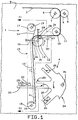
- Number 1 in Figure 1 indicates a device for feeding portions or sheets 2 of wrapping material, cut off a continuous strip 3 wound off a reel (not shown), to a packing line indicated as a whole by 4.
- Device 1 comprises two rollers 5 and 6 rotating about respective horizontal parallel axes, and which, like all the other rollers referred to hereinafter, present a width at least equal to that of strip 3. Rollers 5 and 6 are fitted coaxially and idly to respective shafts 7 and 8 fitted to a vertical wall 9 forming part of the bed of a packing machine (not shown). Strip 3 runs between rollers 5 and 6, and then about an idle guide roller 10 supported on a shaft 11 fitted perpendicularly to wall 9, beneath rollers 5 and 6.
- strip 3 Downstream from roller 10, strip 3 runs about a conveyor element consisting of a roller 12 fitted to a shaft 13 in turn fitted perpendicularly to wall 9 and rotated intermittently anticlockwise by drive means (not shown).
- the two lateral edges of the cylindrical surface of roller 12 run along respective substantially vertical branches 14 of two known side by side suction belts 15 looped about a bottom and top roller 16 and 17 (see also Figure 2) fitted to respective horizontal shafts 18 and 19 rotated intermittently clockwise by drive means (not shown).
- Belts 15 constitute the feed means described and illustrated in British Patent n. 1,550,136 referred to previously, and are made of material permeable to air. As shown schematically in Figure 1, inside the loop defined by each belt 15, a chamber 15' communicating with a suction source (not shown) extends along the branch of each belt 15 extending substantially between rollers 12 and 16.
- a horizontal supporting surface 21 fitted rigidly to wall 9 and onto which are fed successively in known manner (not shown), and in a direction perpendicular to the Figure 2 plane, products consisting, for example of packets of cigarettes 22.
- Packing line 4 comprises a wrapping wheel 24 presenting radial seats 25, and supported on and rotated intermittently anticlockwise by a shaft 26 extending perpendicularly from wall 9. As will be made clear later on, the packets 22 fed to packing line 4 by push element 23 are fed into respective seats 25 on wrapping wheel 24.
- blade 28 Inside a radial cavity 27 on roller 12, there is fitted a blade 28 extending parallel to the axis of roller 12, and the cutting edge of which projects slightly (e.g. by three-tenths of a millimeter) from the cylindrical surface of roller 12.
- blade 28 will also be referred to as a "movable cutting means”.
- wall 9 Upstream, in the traveling direction of strip 3, from the point of contact between roller 12 and belts 15, wall 9 supports fixed cutting means consisting of a blade 29 extending in the vertical plane containing the axis of roller 12.
- Blade 29 is substantially C-shaped ( Figure 2), and presents two downward-facing lateral cutting edges 30 cooperating, as roller 12 rotates, with respective lateral portions of the cutting edge of blade 28, so as to cyclically make in strip 3 two longitudinally-aligned transverse lateral cuts 31 ( Figure 3) wider than belts 15.
- wall 9 also supports fixed cutting means consisting of a blade 32 extending in the horizontal plane containing the axis of roller 12.
- Blade 32 is located centrally in relation to the axial dimension of roller 12, and is narrower than the distance between the two belts 15. As roller 12 rotates, blade 32 cooperates with blade 28 to cyclically make in strip 3 a central transverse cut 33 ( Figure 3) of a width equal to or no smaller than the distance between two longitudinally-aligned cuts 31.
- strip 3 is drawn by the combined action of rollers 5 and 6 and belts 15 to transfer station 20.
- blade 28 cooperates with blade 29 to make in strip 3 two longitudinally-aligned lateral cuts 31, which are then joined by blades 28 and 32 making a central cut 33, so as to detach a sheet 2 from strip 3.
- Each sheet 2 is then fed by belts 15 to transfer station 20 where push element 23 inserts sheet 2, together with packet 22, into a seat 25 on wrapping wheel 24.
- device 1 as described is not only extremely compact but also more straightforward and cheaper to produce as compared with the known devices described.
- strip 3 and sheets 2 may be fed to packing line 4 by means of a single suction belt 15 acting on only one lateral portion of strip 3 and sheets 2.
- a blade (not shown), supported in the same way as blade 29 but having only one cutting edge, would make a transverse cut, together with rotary blade 28, in the portion of strip 3 later to be retained by said suction belt 15; and blade 32, together with rotary blade 28, would complete the cut to detach sheets 2 in the same way as already described.
- blades 29 and 32 may present a number of cutting edges arranged "comb fashion" and offset on one blade in relation to the other. In which case, blade 29, together with rotary blade 28, would make in strip 3 a number of transverse cuts, one for each cutting edge, which would then be joined by blade 32 cooperating with rotary blade 28.
Landscapes
- Engineering & Computer Science (AREA)
- Mechanical Engineering (AREA)
- Auxiliary Devices For And Details Of Packaging Control (AREA)
- Wrapping Of Specific Fragile Articles (AREA)
- Basic Packing Technique (AREA)
Claims (5)
- Ein Verfahren zum Zuführen von Abschnitten eines Umhüllungsmaterials zu einer Verpackungsstraße, wobei die genannten Abschnitte (2) nacheinander von einem kontinuierlichen Streifen (3) abgetrennt werden; das Verfahren umfaßt Schritte, die bestehen im Ausführen von mindestens einem ersten teilweisen Quer-Trennschnitt (31) in dem besagten Streifen (3) mittels einer ersten festen Schneideinrichtung (29), die mit einer bewegbare Schneideinrichtung (28) zusammenwirkt; im Ausführen von mindestens einem zweiten teilweisen Quer-Trennschnitt (33), welcher in Längsrichtung mit dem erwähnten ersten teilweisen Quer-Trennschnitt (31) ausgerichtet ist, in dem besagten Streifen (3) und im Vervollständigen der Abtrennung des genannten Abschnitts (2) mittels einer zweiten festen Schneideinrichtung (32); der besagte Streifen wird im Verlauf des Ausführens des erwähnten zweiten teilweisen Quer-Trennschnitts (33) von Fördereinrichtungen (15) gezogen, die keine Beziehung zu dem Streifenbereich haben, in dem der zweite teilweise Quer-Trennschnitt (33) ausgeführt werden soll, dadurch gekennzeichnet, daß die genannte zweite feste Schneideinrichtung (32) mit der erwähnten bewegbaren Schneideinrichtung (28) zusammenarbeitet.
- Ein Verfahren nach Anspruch 1, dadurch gekennzeichnet, daß die erwähnte bewegbare Schneideinrichtung (28) von einem stromauf von den genannten Fördereinrichtungen (15) angeordneten Streifen-Förderelement (12) getragen wird.
- Eine Vorrichtung zum Zuführen von Abschnitten eines Umhüllungsmaterials zu einer Verpackungsstraße, wobei die genannten Abschnitte (2) nacheinander von einem kontinuierlichen Streifen (3) abgetrennt werden; die Vorrichtung umfaßt eine erste feste Schneideinrichtung (29) sowie eine bewegbare Schneideinrichtung (28), die miteinander zusammenarbeiten, um im Verlauf eines Abtrennens eines jeden Abschnitts (2) mindestens einen ersten teilweisen Quer-Trennschnitt (31) in dem besagten Streifen (3) auszuführen; eine zweite feste Schneideinrichtung (32), um in dem besagten Streifen (3) mindestens einen zweiten teilweisen Quer-Trennschnitt (33), der in Längsrichtung mit dem erwähnten ersten teilweisen Quer-Trennschnitt (31) ausgerichtet ist sowie die Abtrennung des genannten Abschnitts (2) vervollständigt, auszuführen; Fördereinrichtungen (15) sind vorgesehen, um den besagten Streifen (3) im Verlauf des Ausführens des erwähnten zweiten teilweisen Quer-Trennschnitts (33) zu ziehen, und diese haben keine Beziehung zu dem Streifenbereich, in dem der zweite teilweise Quer-Trennschnitt (33) ausgeführt werden soll, dadurch gekennzeichnet, daß die genannte zweite feste Schneideinrichtung (32) mit der erwähnten bewegbaren Schneideinrichtung (28) zusammenarbeitet.
- Eine Vorrichtung nach Anspruch 3, dadurch gekennzeichnet, daß sie ein Streifen-Förderelement (12) umfaßt, das stromauf von den genannten Fördereinrichtungen (15) angeordnet ist und die erwähnte bewegbare Schneideinrichtung (28) trägt.
- Eine Vorrichtung nach Anspruch 4, dadurch gekennzeichnet, daß das besagte Streifen-Förderelement aus einer um ihre Achse drehenden Walze (12) besteht und mindestens ein Teil deren zylindrischer Umfangsfläche für Luft durchlässig sowie an eine Saugquelle (35') anschließbar ist.
Applications Claiming Priority (2)
| Application Number | Priority Date | Filing Date | Title |
|---|---|---|---|
| IT93BO276 IT1263436B (it) | 1993-06-18 | 1993-06-18 | Metodo e dispositivo per l'alimentazione di spezzoni di materiale di incarto ad una linea di impacchettamento. |
| ITBO930276 | 1993-06-18 |
Publications (2)
| Publication Number | Publication Date |
|---|---|
| EP0629552A1 EP0629552A1 (de) | 1994-12-21 |
| EP0629552B1 true EP0629552B1 (de) | 1997-08-27 |
Family
ID=11339133
Family Applications (1)
| Application Number | Title | Priority Date | Filing Date |
|---|---|---|---|
| EP94108703A Expired - Lifetime EP0629552B1 (de) | 1993-06-18 | 1994-06-07 | Verfahren und Vorrichtung zum Beschicken einer Verpackungsstrasse mit Abschnitten von Wickelmaterial |
Country Status (6)
| Country | Link |
|---|---|
| US (1) | US5461954A (de) |
| EP (1) | EP0629552B1 (de) |
| JP (1) | JPH07149320A (de) |
| BR (1) | BR9402462A (de) |
| DE (1) | DE69405161T2 (de) |
| IT (1) | IT1263436B (de) |
Families Citing this family (10)
| Publication number | Priority date | Publication date | Assignee | Title |
|---|---|---|---|---|
| DE4411358B4 (de) * | 1994-03-31 | 2005-10-27 | Focke & Co.(Gmbh & Co. Kg) | Vorrichtung zum Herstellen von Verpackungen aus insbesondere dünner Kunststofffolie |
| DE19540148C1 (de) * | 1995-10-27 | 1997-04-24 | Windmoeller & Hoelscher | Vorrichtung zum Abtrennen von Zetteln von einer kontinuierlich geförderten Zettelbahn |
| US5771662A (en) * | 1996-06-28 | 1998-06-30 | Douglas Machine Limited Liability Company | Apparatus and methods for producing shrink wrap packaging |
| NL1019933C2 (nl) * | 2002-02-08 | 2003-08-11 | Fountain Tech Bv | Transportstans. |
| US7032360B2 (en) * | 2003-10-29 | 2006-04-25 | Douglas Machine, Inc. | Apparatus and methods for producing shrink wrap packaging |
| ITBO20030706A1 (it) * | 2003-11-21 | 2005-05-22 | Gd Spa | Unita' di incarto di prodotti. |
| US20050193880A1 (en) * | 2004-03-04 | 2005-09-08 | Yi-Chiu Chao | Packing machine having film conveying device and film cutting device |
| DE102004020748A1 (de) * | 2004-04-27 | 2005-12-01 | Focke & Co.(Gmbh & Co. Kg) | Vorrichtung zum Herstellen von Zigarettenpackungen |
| DE602009000911D1 (de) * | 2008-12-02 | 2011-04-28 | Gd Spa | Verpackungsverfahren und Einheit zum Falten eines Verpackungsmaterialblatts über einen parallelepiped-förmigen Artikel |
| DE102015220738A1 (de) * | 2015-10-23 | 2017-04-27 | Chocal Aluminiumverpackungen Gmbh | Vorrichtung und Verfahren zum Abtrennen und Bereitstellen einer Folienteilstückeinheit von einem Lebensmittelverpackungsfolienband |
Family Cites Families (11)
| Publication number | Priority date | Publication date | Assignee | Title |
|---|---|---|---|---|
| DE1252575B (de) * | 1967-10-19 | 3evelsberg Alfred Schmermund (Westf.) | Packmaschine, nsbesondere Zigarettenpackmaschine | |
| GB1037261A (en) * | 1962-03-08 | 1966-07-27 | Derek Henry Youngman | Improvements in or relating to the cutting of desired lengths from a web of wrapper material |
| GB1071205A (en) * | 1965-05-22 | 1967-06-07 | Schmermund Alfred | Improvements in or relating to packing machines |
| US3355166A (en) * | 1965-06-24 | 1967-11-28 | St Regis Paper Co | Automatic wrapping machine including a suction stop plate |
| DE2407767C3 (de) * | 1974-02-19 | 1978-04-27 | Focke & Pfuhl, 3090 Verden | Verfahren und Vorrichtung zum Einschlagen von Zigarettengruppen o.dgl |
| US4388794A (en) * | 1975-07-11 | 1983-06-21 | Focke & Pfuhl | Apparatus for cutting and transporting blanks from a web of flexible material |
| DE2530992C3 (de) * | 1975-07-11 | 1980-01-31 | Focke & Pfuhl, 2810 Verden | Vorrichtung zum Herstellen von Verpackungszuschnitten |
| DE2949685A1 (de) * | 1979-12-11 | 1981-06-19 | Focke & Co, 2810 Verden | Vorrichtung zum herstellen von packungszuschnitten durch abtrennen von einer fortlaufenden bahn |
| DE3131687A1 (de) * | 1981-08-11 | 1983-03-03 | Focke & Co, 2810 Verden | "verpackungs-vorrichtung zum herstellen von zuschnitten und zufuehren derselben in einer verpackungsstation" |
| DE3340408A1 (de) * | 1983-11-09 | 1985-05-15 | Focke & Co, 2810 Verden | Vorrichtung zum einhuellen von gegenstaenden, insbesondere zigaretten-gruppen |
| US5327702A (en) * | 1991-08-01 | 1994-07-12 | Molins Plc | Wrapping articles |
-
1993
- 1993-06-18 IT IT93BO276 patent/IT1263436B/it active IP Right Grant
-
1994
- 1994-06-06 US US08/254,130 patent/US5461954A/en not_active Expired - Fee Related
- 1994-06-07 DE DE69405161T patent/DE69405161T2/de not_active Expired - Fee Related
- 1994-06-07 EP EP94108703A patent/EP0629552B1/de not_active Expired - Lifetime
- 1994-06-17 BR BR9402462A patent/BR9402462A/pt not_active Application Discontinuation
- 1994-06-20 JP JP13763994A patent/JPH07149320A/ja active Pending
Also Published As
| Publication number | Publication date |
|---|---|
| ITBO930276A1 (it) | 1994-12-18 |
| DE69405161D1 (de) | 1997-10-02 |
| JPH07149320A (ja) | 1995-06-13 |
| IT1263436B (it) | 1996-08-05 |
| BR9402462A (pt) | 1995-01-24 |
| US5461954A (en) | 1995-10-31 |
| ITBO930276A0 (it) | 1993-06-18 |
| EP0629552A1 (de) | 1994-12-21 |
| DE69405161T2 (de) | 1998-03-19 |
Similar Documents
| Publication | Publication Date | Title |
|---|---|---|
| US4495746A (en) | Packaging apparatus for producing and feeding blanks to a packaging station | |
| US4524658A (en) | Apparatus for producing packaging blanks | |
| CA1259841A (en) | Process and apparatus for producing blanks for packs | |
| US4385479A (en) | Apparatus for the preparation of packaging blanks by severing from a continuous web | |
| JPH0315442Y2 (de) | ||
| EP0629552B1 (de) | Verfahren und Vorrichtung zum Beschicken einer Verpackungsstrasse mit Abschnitten von Wickelmaterial | |
| US4151699A (en) | Production of discrete blanks for packets | |
| US5179815A (en) | Article wrapping apparatus | |
| US12065278B2 (en) | Unit, apparatus and method for cutting a chain of article | |
| US4603534A (en) | Apparatus for wrapping articles, especially cigarette groups | |
| EP0795472B1 (de) | Verfahren zum Umhüllen von Paketen | |
| US4809575A (en) | Multi-purpose conveyor system | |
| JPH0811568B2 (ja) | 包装材料の供給方法及び装置 | |
| US5533854A (en) | Apparatus for the handling of blank stacks having a band | |
| US4388794A (en) | Apparatus for cutting and transporting blanks from a web of flexible material | |
| JPH10218123A (ja) | シガレット群或いはシガレットパッケージのためのくるみ材料テープを送るための装置 | |
| US3693319A (en) | Wrapping individual slices of food | |
| US5327702A (en) | Wrapping articles | |
| EP0545265B1 (de) | Verfahren und Vorrichtung zum Zuführen von Verpackungsmaterial an einer Verpackungsmaschine | |
| EP0787651A1 (de) | Verfahren zum Zuführen von Zuschnitten eines Wickelmaterials | |
| GB2258225A (en) | Feeding and severing webs; wrapping articles. | |
| EP0573944B1 (de) | Zuführ- und Schneidevorrichtung für Wickelmaterial in einer Einwickelmaschine für Gegenstände | |
| EP0722898B1 (de) | Verfahren zum Fördern von Bogenmaterial | |
| US3143837A (en) | Container sealing machine | |
| EP0900730B1 (de) | Verfahren und Einheit zum Zuführen von flachen Artikeln |
Legal Events
| Date | Code | Title | Description |
|---|---|---|---|
| PUAI | Public reference made under article 153(3) epc to a published international application that has entered the european phase |
Free format text: ORIGINAL CODE: 0009012 |
|
| AK | Designated contracting states |
Kind code of ref document: A1 Designated state(s): DE FR GB IT |
|
| 17P | Request for examination filed |
Effective date: 19950530 |
|
| GRAG | Despatch of communication of intention to grant |
Free format text: ORIGINAL CODE: EPIDOS AGRA |
|
| RAP1 | Party data changed (applicant data changed or rights of an application transferred) |
Owner name: G.D SOCIETA' PER AZIONI |
|
| 17Q | First examination report despatched |
Effective date: 19960918 |
|
| GRAH | Despatch of communication of intention to grant a patent |
Free format text: ORIGINAL CODE: EPIDOS IGRA |
|
| GRAH | Despatch of communication of intention to grant a patent |
Free format text: ORIGINAL CODE: EPIDOS IGRA |
|
| GRAA | (expected) grant |
Free format text: ORIGINAL CODE: 0009210 |
|
| AK | Designated contracting states |
Kind code of ref document: B1 Designated state(s): DE FR GB IT |
|
| ITF | It: translation for a ep patent filed | ||
| REF | Corresponds to: |
Ref document number: 69405161 Country of ref document: DE Date of ref document: 19971002 |
|
| ET | Fr: translation filed | ||
| PLBE | No opposition filed within time limit |
Free format text: ORIGINAL CODE: 0009261 |
|
| STAA | Information on the status of an ep patent application or granted ep patent |
Free format text: STATUS: NO OPPOSITION FILED WITHIN TIME LIMIT |
|
| 26N | No opposition filed | ||
| PGFP | Annual fee paid to national office [announced via postgrant information from national office to epo] |
Ref country code: FR Payment date: 19990421 Year of fee payment: 6 |
|
| PGFP | Annual fee paid to national office [announced via postgrant information from national office to epo] |
Ref country code: DE Payment date: 19990531 Year of fee payment: 6 |
|
| PGFP | Annual fee paid to national office [announced via postgrant information from national office to epo] |
Ref country code: GB Payment date: 19990628 Year of fee payment: 6 |
|
| PG25 | Lapsed in a contracting state [announced via postgrant information from national office to epo] |
Ref country code: GB Free format text: LAPSE BECAUSE OF NON-PAYMENT OF DUE FEES Effective date: 20000607 |
|
| GBPC | Gb: european patent ceased through non-payment of renewal fee |
Effective date: 20000607 |
|
| PG25 | Lapsed in a contracting state [announced via postgrant information from national office to epo] |
Ref country code: FR Free format text: LAPSE BECAUSE OF NON-PAYMENT OF DUE FEES Effective date: 20010228 |
|
| REG | Reference to a national code |
Ref country code: FR Ref legal event code: ST |
|
| PG25 | Lapsed in a contracting state [announced via postgrant information from national office to epo] |
Ref country code: DE Free format text: LAPSE BECAUSE OF NON-PAYMENT OF DUE FEES Effective date: 20010403 |
|
| PG25 | Lapsed in a contracting state [announced via postgrant information from national office to epo] |
Ref country code: IT Free format text: LAPSE BECAUSE OF NON-PAYMENT OF DUE FEES Effective date: 20050607 |