EP0629145B1 - Tragbares elektronenstahlsystem und verfahren - Google Patents
Tragbares elektronenstahlsystem und verfahren Download PDFInfo
- Publication number
- EP0629145B1 EP0629145B1 EP94903636A EP94903636A EP0629145B1 EP 0629145 B1 EP0629145 B1 EP 0629145B1 EP 94903636 A EP94903636 A EP 94903636A EP 94903636 A EP94903636 A EP 94903636A EP 0629145 B1 EP0629145 B1 EP 0629145B1
- Authority
- EP
- European Patent Office
- Prior art keywords
- electron beam
- reaction chamber
- treatment
- effluent
- influent
- Prior art date
- Legal status (The legal status is an assumption and is not a legal conclusion. Google has not performed a legal analysis and makes no representation as to the accuracy of the status listed.)
- Expired - Lifetime
Links
Images


Classifications
-
- H—ELECTRICITY
- H01—ELECTRIC ELEMENTS
- H01J—ELECTRIC DISCHARGE TUBES OR DISCHARGE LAMPS
- H01J33/00—Discharge tubes with provision for emergence of electrons or ions from the vessel; Lenard tubes
- H01J33/02—Details
-
- B—PERFORMING OPERATIONS; TRANSPORTING
- B01—PHYSICAL OR CHEMICAL PROCESSES OR APPARATUS IN GENERAL
- B01D—SEPARATION
- B01D53/00—Separation of gases or vapours; Recovering vapours of volatile solvents from gases; Chemical or biological purification of waste gases, e.g. engine exhaust gases, smoke, fumes, flue gases, aerosols
- B01D53/007—Separation of gases or vapours; Recovering vapours of volatile solvents from gases; Chemical or biological purification of waste gases, e.g. engine exhaust gases, smoke, fumes, flue gases, aerosols by irradiation
-
- B—PERFORMING OPERATIONS; TRANSPORTING
- B01—PHYSICAL OR CHEMICAL PROCESSES OR APPARATUS IN GENERAL
- B01D—SEPARATION
- B01D53/00—Separation of gases or vapours; Recovering vapours of volatile solvents from gases; Chemical or biological purification of waste gases, e.g. engine exhaust gases, smoke, fumes, flue gases, aerosols
- B01D53/32—Separation of gases or vapours; Recovering vapours of volatile solvents from gases; Chemical or biological purification of waste gases, e.g. engine exhaust gases, smoke, fumes, flue gases, aerosols by electrical effects other than those provided for in group B01D61/00
- B01D53/323—Separation of gases or vapours; Recovering vapours of volatile solvents from gases; Chemical or biological purification of waste gases, e.g. engine exhaust gases, smoke, fumes, flue gases, aerosols by electrical effects other than those provided for in group B01D61/00 by electrostatic effects or by high-voltage electric fields
-
- B—PERFORMING OPERATIONS; TRANSPORTING
- B01—PHYSICAL OR CHEMICAL PROCESSES OR APPARATUS IN GENERAL
- B01D—SEPARATION
- B01D53/00—Separation of gases or vapours; Recovering vapours of volatile solvents from gases; Chemical or biological purification of waste gases, e.g. engine exhaust gases, smoke, fumes, flue gases, aerosols
- B01D53/34—Chemical or biological purification of waste gases
- B01D53/74—General processes for purification of waste gases; Apparatus or devices specially adapted therefor
- B01D53/75—Multi-step processes
-
- B—PERFORMING OPERATIONS; TRANSPORTING
- B01—PHYSICAL OR CHEMICAL PROCESSES OR APPARATUS IN GENERAL
- B01J—CHEMICAL OR PHYSICAL PROCESSES, e.g. CATALYSIS OR COLLOID CHEMISTRY; THEIR RELEVANT APPARATUS
- B01J19/00—Chemical, physical or physico-chemical processes in general; Their relevant apparatus
- B01J19/08—Processes employing the direct application of electric or wave energy, or particle radiation; Apparatus therefor
- B01J19/081—Processes employing the direct application of electric or wave energy, or particle radiation; Apparatus therefor employing particle radiation or gamma-radiation
- B01J19/085—Electron beams only
-
- B—PERFORMING OPERATIONS; TRANSPORTING
- B09—DISPOSAL OF SOLID WASTE; RECLAMATION OF CONTAMINATED SOIL
- B09C—RECLAMATION OF CONTAMINATED SOIL
- B09C1/00—Reclamation of contaminated soil
-
- B—PERFORMING OPERATIONS; TRANSPORTING
- B09—DISPOSAL OF SOLID WASTE; RECLAMATION OF CONTAMINATED SOIL
- B09C—RECLAMATION OF CONTAMINATED SOIL
- B09C1/00—Reclamation of contaminated soil
- B09C1/06—Reclamation of contaminated soil thermally
-
- B—PERFORMING OPERATIONS; TRANSPORTING
- B09—DISPOSAL OF SOLID WASTE; RECLAMATION OF CONTAMINATED SOIL
- B09C—RECLAMATION OF CONTAMINATED SOIL
- B09C1/00—Reclamation of contaminated soil
- B09C1/08—Reclamation of contaminated soil chemically
-
- H—ELECTRICITY
- H01—ELECTRIC ELEMENTS
- H01J—ELECTRIC DISCHARGE TUBES OR DISCHARGE LAMPS
- H01J33/00—Discharge tubes with provision for emergence of electrons or ions from the vessel; Lenard tubes
-
- B—PERFORMING OPERATIONS; TRANSPORTING
- B01—PHYSICAL OR CHEMICAL PROCESSES OR APPARATUS IN GENERAL
- B01D—SEPARATION
- B01D2257/00—Components to be removed
- B01D2257/70—Organic compounds not provided for in groups B01D2257/00 - B01D2257/602
- B01D2257/708—Volatile organic compounds V.O.C.'s
-
- B—PERFORMING OPERATIONS; TRANSPORTING
- B01—PHYSICAL OR CHEMICAL PROCESSES OR APPARATUS IN GENERAL
- B01D—SEPARATION
- B01D2259/00—Type of treatment
- B01D2259/80—Employing electric, magnetic, electromagnetic or wave energy, or particle radiation
- B01D2259/812—Electrons
-
- B—PERFORMING OPERATIONS; TRANSPORTING
- B01—PHYSICAL OR CHEMICAL PROCESSES OR APPARATUS IN GENERAL
- B01J—CHEMICAL OR PHYSICAL PROCESSES, e.g. CATALYSIS OR COLLOID CHEMISTRY; THEIR RELEVANT APPARATUS
- B01J2219/00—Chemical, physical or physico-chemical processes in general; Their relevant apparatus
- B01J2219/00049—Controlling or regulating processes
- B01J2219/00051—Controlling the temperature
- B01J2219/00074—Controlling the temperature by indirect heating or cooling employing heat exchange fluids
- B01J2219/00087—Controlling the temperature by indirect heating or cooling employing heat exchange fluids with heat exchange elements outside the reactor
- B01J2219/00103—Controlling the temperature by indirect heating or cooling employing heat exchange fluids with heat exchange elements outside the reactor in a heat exchanger separate from the reactor
-
- B—PERFORMING OPERATIONS; TRANSPORTING
- B01—PHYSICAL OR CHEMICAL PROCESSES OR APPARATUS IN GENERAL
- B01J—CHEMICAL OR PHYSICAL PROCESSES, e.g. CATALYSIS OR COLLOID CHEMISTRY; THEIR RELEVANT APPARATUS
- B01J2219/00—Chemical, physical or physico-chemical processes in general; Their relevant apparatus
- B01J2219/00049—Controlling or regulating processes
- B01J2219/00051—Controlling the temperature
- B01J2219/0015—Controlling the temperature by thermal insulation means
- B01J2219/00153—Vacuum spaces
-
- B—PERFORMING OPERATIONS; TRANSPORTING
- B01—PHYSICAL OR CHEMICAL PROCESSES OR APPARATUS IN GENERAL
- B01J—CHEMICAL OR PHYSICAL PROCESSES, e.g. CATALYSIS OR COLLOID CHEMISTRY; THEIR RELEVANT APPARATUS
- B01J2219/00—Chemical, physical or physico-chemical processes in general; Their relevant apparatus
- B01J2219/00049—Controlling or regulating processes
- B01J2219/00051—Controlling the temperature
- B01J2219/00159—Controlling the temperature controlling multiple zones along the direction of flow, e.g. pre-heating and after-cooling
-
- C—CHEMISTRY; METALLURGY
- C02—TREATMENT OF WATER, WASTE WATER, SEWAGE, OR SLUDGE
- C02F—TREATMENT OF WATER, WASTE WATER, SEWAGE, OR SLUDGE
- C02F1/00—Treatment of water, waste water, or sewage
- C02F1/008—Control or steering systems not provided for elsewhere in subclass C02F
-
- C—CHEMISTRY; METALLURGY
- C02—TREATMENT OF WATER, WASTE WATER, SEWAGE, OR SLUDGE
- C02F—TREATMENT OF WATER, WASTE WATER, SEWAGE, OR SLUDGE
- C02F1/00—Treatment of water, waste water, or sewage
- C02F1/30—Treatment of water, waste water, or sewage by irradiation
- C02F1/305—Treatment of water, waste water, or sewage by irradiation with electrons
Definitions
- This invention relates generally to the processing and/or chemical conversion of gases, vapors, aerosols, and suspended particulates using electron beams. These terms are used interchangeably herein and it should therefore be understood that if the word gas is used in the specification or the claims, it is intended to mean gas or gases, vapor or vapors, aerosol or aerosols and suspended particulates.
- this invention relates to a transportable system for the conversion of toxic waste, especially volatile organic compounds, to environmentally acceptable compounds or elements.
- Air stripping and vacuum extraction are dispersion technologies which extract contaminants from soil and groundwater. However, venting contaminants directly to the atmosphere is environmentally undesirable. Processing of the contaminants before release or disposal is required and is addressed by this invention, as discussed below.
- Carbon containment is a collection technology in which contaminants are passed through carbon (or other adsorbent) filled canisters to adsorb the contaminants.
- contaminants In remediation systems for removal of volatile organic compounds from soil and groundwater, contaminants may be removed from the ground or groundwater by vacuum extraction or air stripped.
- effluent treatment systems typically found at refineries or chemical plants, the contaminants may be the discharge of an industrial process.
- volatile organic contaminants are adsorbed onto carbon, while the remaining portion of the extracted air, steam, or process effluent is released to the environment along with any contaminants the carbon fails to remove.
- Carbon canisters with adsorbed toxics pose a disposal problem of their own, which is further complicated by the transport problem to move canisters to a treatment facility.
- containment of the adsorbed toxics whether kept in a single location or moved, is not universally effective, as some volatile organic compounds and other pollutants have low adsorptivity.
- Incineration is a technique used to destroy contaminants through high-temperature burning.
- the vapors may come from vacuum extraction wells, air strippers, or industrial process effluent.
- Destruction of these contaminants by incineration is often incomplete, however, and incomplete destruction can be expected to produce (and release to the atmosphere) compounds more hazardous than the original contaminants.
- incineration is often undesirable at refineries and chemical plants because of the dangers presented by the proximity of flammable substances to the incinerator's high temperatures.
- incineration is politically and socially undesirable.
- Electron beams are used to process or convert toxic and nontoxic compounds to different compounds or elements. Influents consisting of gases, aerosols, and/or suspended particulates enter a reaction chamber (or transformation plenum) into which a beam of electrons is injected. These electrons interact with the influent to chemically transform compounds into elements or other compounds.
- Electron beams have previously been used to reduce emissions of sulfur oxides (SO x ) and/or nitrogen oxides (NO x ) from conventional power plant facilities.
- SO x sulfur oxides
- NO x nitrogen oxides
- US-A-4,915,916 discloses a method for treating waste gas by radiation with electron beams of a part of the gas to be treated, thereby forming active species which are then fed to the main waste gas duct to change noxious gas ingredients into the form of a mist or dust which can be collected.
- Each power plant effluent treatment system is designed to operate with a single power plant. These systems are stationary and permanently fixed in one place. They are not transportable.
- composition of a power plant's effluent is relatively unchanging, prior art effluent is relatively unchanging, prior art effluent treatment systems were not designed to be easily reconfigured.
- Electron beam radiation has also been used to convert organic contaminants in drinking water to nontoxic forms. Like the power plant effluent treatment systems, however, water treatment facilities are not designed to be transportable. Rather, prior art electron beam water treatment systems are designed to meet the requirements of a single water treatment plant. Thus, the prior art does not address the problems of transportability of an electron beam system from site to site or the adaptability of the system to the needs of each particular site.
- EP-A-0 659 297 is comprises in the state of the art under Article 54(3) and (4) EPC in the contracting states of DE,FR,GB.
- the document discloses a volatile organic compound treatment system using electron interaction.
- an electron beam generator and a reaction chamber are mounted on a trailer (or other vehicle) along with any influent preprocessing modules (such as particulate filters, moisture traps, heaters, coolers, pumps, orifices, nozzles, and/or valves), effluent post-processing modules (such as a carbon canister and a caustic scrubber for hydrochloric acid) and system instrumentation and controls.
- influent preprocessing modules such as particulate filters, moisture traps, heaters, coolers, pumps, orifices, nozzles, and/or valves
- effluent post-processing modules such as a carbon canister and a caustic scrubber for hydrochloric acid
- Influent gases from a vacuum extraction system or other source are fed to the system, and any undesirable compounds in the gases are either transformed to benign elements or compounds or are removed (or further transformed) by the effluent treatment modules.
- the system may be moved from site to site and is designed to meet all applicable highway weight and size restrictions. In addition, the
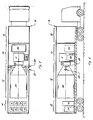
- FIGS 1 and 2 show top and side views of a transportable electron beam conversion system according to this invention.
- An electron beam generator subsystem 10 a transformation subsystem 12, and influent pre-processing and effluent post-processing modules 14 are mounted in an enclosed trailer 16.
- the instrumentation and controls required to monitor and operate the system may be located in a control room 18 at one end of trailer 16.
- Control room 18 has suitable protection for its occupants from radiation and airborne hazards.
- Influent e.g., untreated material
- outlet stack 24 leaves the system through outlet stack 24.
- the entire toxic remediation system is contained in trailer 16.
- Performance and efficiency of the electron beam conversion system are dependent upon many interrelated factors, including the shape, dimensions, and total volume of the reaction chamber; the density and density distribution of the reaction chamber contents; and the characteristics of the electron beam, such as its cross-sectional dimensions, the pattern of directions of the incident electrons, the kinetic energies and energy distribution of the electrons, the peak and average power of the beam, and the dose rate.
- the system's performance may be enhanced by the generation of secondary electrons upon collision of electrons in the incident beam with the chamber and/or chamber contents.
- electron beam generator subsystem 10 is a 2.5 MeV pulsed linear electron accelerator 11.
- This unit includes a high-vacuum cylindrical envelope which contains an electron gun comprising an electron source (heated cathode), accelerating electrode (anode), and a control electrode (grid).
- the electron gun injects electrons into an evacuated waveguide which includes a series of resonant cavities in which the electrons are accelerated sequentially, using energy derived from a pulsed microwave source.
- the microwave source is a magnetron.
- a modulator 26 contains pulse generating components.
- the subsystem also includes heat exchanger 28 for cooling some elements of the subsystem.
- the preferred embodiment employs a microwave-pulsed linear electron accelerator to meet the size, power, and weight requirements of the transportable conversion system.
- Other electron beam sources may be used, however, without departing from the scope of this invention.
- linear induction accelerators have been used in the laboratory with limited success and may be used in this application if the requirements for transportability and reliability are met.
- electron sources in which electron energy is determined solely by power supply voltage, without microwave or induction boost can also be used if the transportability and reliability requirements are met.
- the average beam power may be made adjustable and the modulator may also be selected to permit modifications to adjust the peak beam power.
- FIG. 3 is a schematic cross-sectional view of transformation subsystem 12 as well as a portion of the electron beam generator subsystem 10, particularly the output end of accelerator 11.
- an accelerator vacuum window 30 (preferably 1 to 2 mils titanium) is positioned at the accelerator outlet.
- Other materials may be used (such as stainless steel, beryllium or ceramics) and other material thicknesses may be used for window 30 without departing from the scope of this invention.
- the goal in selecting a material and thickness for window 30 is to provide a desired scatter angle (as discussed below) and low energy loss while still maintaining a vacuum and good thermal conductivity to reduce thermal stresses generated in the window by the electron beam. Thickness of window 30 will depend on the power and energy of the electron beam source, the density of the material chosen for the window, and mechanical stresses created in the window during operation of the system.
- the effective electron beam diameter may be enlarged, for example by use of quadrapole coils 27, thereby reducing thermal stresses by distributing beam power over a larger area of the window.
- Window 30 may also be water cooled to prevent overheating.
- the electron beam from accelerator 11 travels through window 30 into a small chamber 29 before passing into the interior of transformation subsystem 12. Chamber 29 is purged by a non-reactive gas such as nitrogen to eliminate ozone produced by the interaction of electrons with oxygen and to aid in cooling the window.
- a second window 36 is disposed between window 30 and the interior of chamber 32 to prevent any contact between material in chamber 32 and window 30.
- Window 36 may be formed from sapphire, mica, ceramic, or other material resistant to the acids that may be generated in the transformation process. The thickness of window 36 depends on, among other things, the material chosen and the operating pressure within chamber 32. In the preferred embodiment, window 36 is formed from 3 mil thick sapphire.
- chamber 29 is maintained at a pressure greater than the reaction chamber pressure to inhibit backflow of material from the reaction chamber toward window 30 in case of breach or failure of window 36.
- window 36 is omitted and noncontaminated flowing gas (such as air) is used to prevent contact between the reaction chamber contents and window 30.
- noncontaminated flowing gas such as air
- Radiation shielding reduces to safe levels the emission of Xrays or other radiation generated by collisions of electrons with materials in their paths.
- shield 70 surrounds the outlet nozzle of the accelerator.
- Shielding may be formed from steel, concrete, lead, or any other suitable material. Other shielding is placed around the system as needed to meet with regulatory requirements and to permit it to be safely operated in the presence of people.
- Transformation subsystem 12 includes a self-shielded, chemically resistant transformation plenum comprising a reaction chamber 32 of nonmetallic material such as porcelain, polyethylene, polyurethane, or resin-impregnated : fiberglass surrounded by an exterior shell 34 of shielding material such as steel.
- the material chosen for the reaction chamber depends on the application, but in any event should preferably minimize the creation of Xrays resulting from collisions with impinging electrons.
- the reaction chamber may be of steel or Inconel of sufficient shielding thickness or other metals if it is determined based on what is being processed that corrosion is not a likely problem.
- the purpose of shell 34 is to reduce to safe levels any Xrays generated by interaction of the electron beam with system components and contents of the reaction chamber.
- Shell 34 may also be formed from concrete, lead, or any shielding substance known in the art.
- Chamber 32 may be formed by depositing a lining material on the interior surface of shell 34.
- chamber 32 may be removable from shell 34 for replacement of a reaction chamber with a new one made from the same material or, if the system is being reconfigured, with a chamber made from a different material adapted to the system's next application.
- chamber 32 and shell 34 are formed as separate elements. Suitable doors or ports are provided in chamber 32 and shell 34, respectively, to provide access to change chamber 32 from time to time and for cleaning and other maintenance.
- reaction chamber 32 optimizes system performance while minimizing the size and weight of chamber 32 and its shield 34. Windows 30 and 36 will cause the electron beam to scatter in varying degrees depending on the window material and thickness. In the preferred embodiment, therefore, reaction chamber 32 is narrow at the electron beam inlet and tapers outwardly to approximate the angle of beam divergence. This reduces the likelihood that untreated materials will bypass the electron beam. In the preferred embodiment, chamber 32 is conical with its narrow diameter at the electron beam inlet.
- a cylindrical portion may be added at the larger end of the conical chamber to provide additional path length for the electron beam.
- Chamber 32 may also be made with a square or polygonal cross-section or of gradually increasing proportion, and may lead to a constant width portion at the large end. Length of reaction chamber 32 is determined by the effective penetration of the scattered electron beam, which, in turn, is determined by the energy of the electrons in the beam and the nature and density of the material within the chamber.
- the size and shape of the reaction chamber, the material and thickness of the windows, the pressure, temperature, mass flow rate and composition of the treated material, the power of the electron beam source, and the energy of the electrons in the beam are interdependent design parameters which may be altered to fit a particular application.
- reaction chamber 32 is therefore designed to optimize contact between the electron beam and the flow stream.
- Influent from a source such as a vacuum extraction system, an air stripping system, an incinerator, a rotary kiln, a bioreactor or an industrial process and like systems enters reaction chamber 32 through inlets 20.
- Elbows 44 on the ends of inlet ducts 20 direct the influent initially into a swirling flow around the end of the chamber farthest from the electron beam source.
- the interaction of swirling influent with inlet ducts 20 and other baffles (not shown)within chamber 32 creates a turbulent flow swirling through the chamber.
- Exit ports 24 are located adjacent to window 36 at the small end of the chamber's cone.
- the turbulent flow of material from the far end of the chamber toward the electron beam source maximizes interaction between the electron beam and the flowing material, thereby maximizing overall system efficiency.
- Additional inlets 41 may be used to add catalysts and/or water to the reaction chamber to aid in the transformation process.
- the inlet ducts may be placed at other locations, such as at the bottom of the reaction chamber, without departing from the scope of the invention.
- the outlet ducts also may be placed at different locations without departing from the spirit of this invention.
- the system can also be used in a batch mode wherein the reaction chamber is filled with untreated material, valves 3 and 4 are closed, and the trapped material is treated with the electron beam to transform the contents to other elements and compounds.
- This "batch" of treated material is thereafter evacuated to the effluent post-processing modules (if post-processing is required) before release.
- FIG 4 is a process flow diagram which shows a possible configuration of influent preprocessing and effluent postprocessing modules.
- Untreated material from source 78 driven by pump 70 enters filter system 76, moisture trap 74, and thermal device 76, before entering reaction chamber 32 via inlets 20 ( Figure 3).
- pump 70 may be positioned on the otherside of plenum or reaction chamber 32. This path or an alternate selected by the operator may be followed depending on the objectives and needs at a particular site. These elements are used to provide influent preprocessing as needed to maintain and optimize the conversion process. If the influent material is not a gas, influent may be directed through atomizer 14 prior to entering reaction chamber 32. A reagent may be added from reagent source 82 to enhance chemical reactions.
- Treated material from reaction chamber 32 may be directed via ports 24 to a conventional scrubber system 50 to post-process any acids formed during the transformation process.
- the scrubbed material may then be directed to vessels 52 and/or 54 containing conventional adsorption materials (such as activated carbon in granular form) to trap any residual undesired material and to serve as a backup system in the event that the electron beam is deactivated prematurely.
- An inert gas such as nitrogen from a source 62 may be used to purge chamber 29.
- valve 13 and sump drain line 31 will drain condensate and sludge from a sump or collector in the chamber and into the inlet gas stream via atomizer 14. Effluent from scrubber 50 may be treated in the same way.
- Influent and effluent gases may be monitored on-line by flow sensors and chemical analysis sensors to determine the composition, temperature, and pressure of input and output material. Operation of the electron beam source may also be monitored by measuring the electron beam current using a current detector torroid 61 surrounding the output beam. Analytical instruments and monitoring equipment may be located in equipment room 18 along with system controls. Computers and computer software may be used in system control. Provision may also be made to control the entire system from a remote location.
- the transportable electron beam conversion system of this invention runs on AC power. If there is no suitable power supply at the conversion site, an AC power generator may be added onto the transport mechanism as to provide total independence to the system.
- the electron beam system of this invention is therefore designed to be both transportable from site to site and reconfigurable to meet the requirements of a particular site.
- System components are removably attached (such as by bolting) to the floor of the trailer.
- one reaction chamber can easily be removed and replaced with another of a different size or configuration; an electron beam source can be exchanged for another with lower or higher energy outputs; scrubbers and adsorption vessels can removed or supplemented.
- the mounting slides for the electron beam source permit the accelerator to be anchored away from the reaction chamber during transport, then moved and correctly aligned into position prior to use at clean-up sites. This feature also contributes to easy maintenance of the electron beam source.
- the transformation process takes place at near ambient temperature.
- material in the reaction chamber may be at an elevated temperature, which in general increases the reaction rates of chemical processes.
- material driven off the adsorbent carbon may be at a high temperature.
- the transformation system may also itself include means to change influent and/or reaction chamber temperature and/or pressure such as a heater, or a cooler, to help regulate the temperature of the transformation process, or a pump and controls to regulate the pressure of the plenum.
- This invention may be used in applications other than toxic waste conversion, such as a step in an industrial process.
- Other modifications covered by this invention will be apparent to those skilled in the art.
Landscapes
- Engineering & Computer Science (AREA)
- Chemical & Material Sciences (AREA)
- Environmental & Geological Engineering (AREA)
- Chemical Kinetics & Catalysis (AREA)
- Life Sciences & Earth Sciences (AREA)
- Analytical Chemistry (AREA)
- Health & Medical Sciences (AREA)
- Oil, Petroleum & Natural Gas (AREA)
- General Chemical & Material Sciences (AREA)
- Soil Sciences (AREA)
- Toxicology (AREA)
- Physics & Mathematics (AREA)
- Plasma & Fusion (AREA)
- Thermal Sciences (AREA)
- General Health & Medical Sciences (AREA)
- Organic Chemistry (AREA)
- Biomedical Technology (AREA)
- Physical Or Chemical Processes And Apparatus (AREA)
- Treating Waste Gases (AREA)
- Fire-Extinguishing Compositions (AREA)
- Processing Of Solid Wastes (AREA)
- Lasers (AREA)
- Analysing Materials By The Use Of Radiation (AREA)
Claims (41)
- Verfahren zum Umwandeln von flüchtigen Dämpfen in einer Reaktionskammer, wobei das Verfahren Einlassen eines Zulauf-Gasstroms in die Reaktionskammer, Leiten eines Elektrodenstrahls von einer Elektronenstrahlquelle in die Reaktionskammer und Erzeugen von Wechselwirkung des stroms mit dem Elektronenstrahl in der Reaktionskammer, um die Dämpfe in annehmbare Verbindungen und Elemente umzuwandeln, und Entfernen des behandelten Gasstroms aus der Reaktionskammer einschließt, dadurch gekennzeichnet, dass die umzuwandelnden Dämpfe flüchtige organische Dämpfe sind.
- Verfahren nach Anspruch 1, das Vorbehandlung des Zulauf-Gasstroms mit wenigstens einem Vorbehandlungsprozess vor Bestrahlung mit dem Elektronenstrahl einschließt.
- Verfahren nach Anspruch 1 oder 2, das Nachbehandlung des Ablauf-Gasstroms mit wenigstens einem Nachbehandlungsprozess nach Bestrahlung mit dem Elektronenstrahl einschließt.
- Verfahren nach Anspruch 2 oder 3, wobei die Zulauf-Vorbehandlung einen Partikelfilterprozess umfasst.
- Verfahren nach Anspruch 2, 3 oder 4, wobei die Zulauf-Vorbehandlung einen Feuchtigkeitsabscheideprozess umfasst.
- Verfahren nach einem der Ansprüche 2 bis 5, wobei die Zulauf-Vorbehandlung einen Zerstäubungsprozess umfasst.
- Verfahren nach einem der Ansprüche 3 bis 6, wobei die Ablauf-Nachbehandlung einen Waschprozess umfasst.
- Verfahren nach einem der Ansprüche 3 bis 7, wobei die Ablauf-Nachbehandlung einen Adsorptionsprozess umfasst.
- Verfahren nach Anspruch 8, wobei der Adsorptionsprozess adsorbierendes Material umfasst, das Aktivkohle in Kornform enthält.
- Verfahren nach einem der vorangehenden Ansprüche, das Leiten des behandelten Ablaufs zur Rückführung zur erneuten Wechselwirkung mit dem Elektronenstrahl zur erneuten Behandlung umfasst.
- Verfahren nach einem der vorangehenden Ansprüche, das Steuern der Temperatur des Gases während der Elektronenbestrahlung umfasst.
- Verfahren nach einem der vorangehenden Ansprüche, das Zusetzen eines Reagens zu dem Gasstrom umfasst, um die Umwandlung zu verstärken.
- Verfahren nach einem der vorangehenden Ansprüche, das Zusetzen eines Katalysators z.u dem Gasstrom umfasst, um die Umwandlung zu verstärken.
- Verfahren nach einem der vorangehenden Ansprüche, das Bewegen der Reaktionskammer und der dazugehörigen Komponenten von einem Ort zu einem anderen umfasst.
- Verfahren nach einem der Ansprüche 1 bis 14, das Überwachen von Funktion der Elektronenstrahlquelle durch Messen des Elektronenstrahlungsstroms einschließt.
- Verfahren nach einem der Ansprüche 1 bis 15, das Ändern des Reaktionskammer- und/oder des Zulaufdrucks einschließt.
- Verfahren nach einem der Ansprüche 1 bis 16, das Hinzufügen von Wasser zu der Reaktionskammer einschließt.
- System zum Umwandeln von flüchtigen organischen Dampf, das eine Elektronenstrahlquelle, eine Reaktionskammer, eine Einrichtung zum Leiten eines Elektronenstrahls von der Elektronenstrahlquelle in die Reaktionskammer, eine Einlasseinrichtung zum Einleiten eines im wesentlichen kontinuierlichen Zulauf-Gasstroms zur Behandlung in die Reaktionskammer zur Bestrahlung mit dem Elektronenstrahl in der Reaktionskammer sowie eine Auslasseinrichtung zum Entfernen eines im Wesentlichen kontinuierlichen Ablauf-Gasstroms aus der Reaktionskammer nach Bestrahlung mit dem Elektronenstrahl in der Elektronenkammer umfasst, wobei das System von Ort zu Ort transportiert werden und umkonfiguriert werden kann, um die Anforderungen eines bestimmten Standorts zu erfüllen.
- System nach Anspruch 18, wobei das System umkonfiguriert werden kann, indem zu ihm eine Einrichtung zur Vorbehandlung des Zulauf-Gasstroms vor Bestrahlung mit dem Elektronenstrahl hinzugefügt oder von ihm entfernt wird.
- System nach Anspruch 18 oder 19, wobei das System umkonfiguriert werden kann, indem zu ihm eine Einrichtung zur Nachbehandlung des Ablauf-Gasstroms nach Bestrahlung mit dem Elektronenstrahl hinzugefügt oder von ihm entfernt wird.
- System nach Anspruch 19 oder 20, wobei die Zulauf-Vorbehandlungseinrichtung einen Partikelfilter umfasst.
- System nach Anspruch 19, 20, oder 21, wobei die Zulauf-Vorbehandlungseinrichtung einen Feuchtigkeitsabscheider umfasst.
- System nach einem der Ansprüche 19 bis 22, wobei die Zulauf-Vorbehandlungseinrichtung eine thermische Vorrichtung umfasst,
- System nach einem der Ansprüche 20 bis 23, wobei die Ablauf-Nachbehandlungseinrichtung ein Waschsystem umfasst.
- System nach einem der Ansprüche 20 bis 24, wobei die Ablauf-Nachbehandlungseinrichtung ein Adsorptionssystem umfasst.
- System nach Anspruch 25, wobei die Ablauf-Nachbehandlungseinrichtung wenigstens adsorbierendes Material umfasst, das Aktivkohle in Komform enthält.
- System nach einem der Ansprüche 18 bis 26, das eine Einrichtung zum Leiten der Ausgabe der Ablauf-Behandlungseinrichtung auf einen Weg zum Zurückführen der Ausgabe zur erneuten Behandlung in der Reaktionskammer zur weiteren Verarbeitung umfasst.
- Verfahren nach einem der Ansprüche 18 bis 27, das eine Einrichtung zum Steuern der Temperatur des Gases in der Reaktionskammer während der Verarbeitung umfasst.
- System nach einem der Ansprüche 18 bis 28, das eine Einrichtung zum Hinzufügen eines Reagens zu dem Gasstrom zum Verstärken der Umwandlung umfasst.
- System nach einem der Ansprüche 18 bis 29, das eine Einrichtung zum Hinzufügen eines Katalysators zu der Reaktionskammer zum Verstärken der Umwandlung umfasst.
- System nach einem der Ansprüche 18 bis 30, das eine Transporteinrichtung zum Bewegen der Komponenten des Systems von einem Standort zu einem anderen umfasst.
- System nach Anspruch 31, wobei die Komponenten abnehmbar an der Transporteinrichtung angebracht sind.
- System nach Anspruch 31 oder 32, das eine Einrichtung zum Schützen der Komponenten während des Transports des Systems von einem Standort zum anderen umfasst,
- System nach Anspruch 33, wobei die Schutzeinrichtung eine Einrichtung zum Verankern der Elektronenstrahlquelle entfernt von der Reaktionskammer während des Transports und eine Einrichtung zum Ausrichten der Elektronenstrahlquelle in Position vor Einsatz an einem bestimmten Standort umfasst.
- System nach einem der Ansprüche 31 bis 34, wobei die Transporteinrichtung zum Einsatz auf öffentlichen Strassen eingerichtet ist.
- System nach Anspruch 35, wobei die Transporteinrichtung ein einzelnes Fahrzeug umfasst.
- System nach einem der Ansprüche 18 bis 36, wobei die Elektronenstrahlquelle ein gepulster EleKtronen-Linearbeschleuniger ist.
- System nach einem der Ansprüche 18 bis 37, das so eingerichtet ist, dass es bei Umgebungstemperatur arbeitet und eine Einrichtung zum Streuen der Elektronen von der Elektronenstrahlquelle in die Reaktionskammer umfasst.
- System nach einem der Ansprüche 18 bis 38, das eine Einrichtung zum Erzeugen einer Wirbelströmung des Gasstroms durch die Reaktionskammer umfasst.
- System nach einem der Ansprüche 18 bis 39, wobei ein Elektronenstrahffenster zwischen der Elektronenstrahlquelle und der Reaktionskammer angeordnet ist.
- System nach Anspruch 40, das eine Einrichtung zum Vergrößern des Elektronenstrahldurchmessers enthält, um thermische Belastungen in dem Fenster zu reduzieren.
Applications Claiming Priority (3)
| Application Number | Priority Date | Filing Date | Title |
|---|---|---|---|
| US07/992,614 US5357291A (en) | 1992-09-08 | 1992-12-18 | Transportable electron beam system and method |
| US992614 | 1992-12-18 | ||
| PCT/US1993/012153 WO1994014531A1 (en) | 1992-12-18 | 1993-12-14 | Transportable electron beam system and method |
Publications (3)
| Publication Number | Publication Date |
|---|---|
| EP0629145A1 EP0629145A1 (de) | 1994-12-21 |
| EP0629145A4 EP0629145A4 (de) | 1995-05-17 |
| EP0629145B1 true EP0629145B1 (de) | 2007-02-28 |
Family
ID=25538535
Family Applications (1)
| Application Number | Title | Priority Date | Filing Date |
|---|---|---|---|
| EP94903636A Expired - Lifetime EP0629145B1 (de) | 1992-12-18 | 1993-12-14 | Tragbares elektronenstahlsystem und verfahren |
Country Status (7)
| Country | Link |
|---|---|
| US (2) | US5357291A (de) |
| EP (1) | EP0629145B1 (de) |
| JP (1) | JP3438817B2 (de) |
| AU (1) | AU697163B2 (de) |
| CA (1) | CA2129853A1 (de) |
| DE (1) | DE69334118T2 (de) |
| WO (1) | WO1994014531A1 (de) |
Families Citing this family (38)
| Publication number | Priority date | Publication date | Assignee | Title |
|---|---|---|---|---|
| JPH0671134A (ja) * | 1992-07-09 | 1994-03-15 | Toshiba Corp | 排ガス中の二酸化炭素除去装置および二酸化炭素除去方法 |
| US5378898A (en) * | 1992-09-08 | 1995-01-03 | Zapit Technology, Inc. | Electron beam system |
| US5357291A (en) * | 1992-09-08 | 1994-10-18 | Zapit Technology, Inc. | Transportable electron beam system and method |
| US5319211A (en) * | 1992-09-08 | 1994-06-07 | Schonberg Radiation Corp. | Toxic remediation |
| US6030506A (en) * | 1997-09-16 | 2000-02-29 | Thermo Power Corporation | Preparation of independently generated highly reactive chemical species |
| US5814821A (en) * | 1996-11-26 | 1998-09-29 | Northrop Grumman Corporation | Mobile irradiation device |
| FR2791276B1 (fr) * | 1999-03-26 | 2002-01-18 | Anne Marie Coudert | Procede pour decomposer les polluants atmospheriques. appareil pour cette realisation |
| US6422002B1 (en) * | 1999-07-23 | 2002-07-23 | The United States Of America As Represented By The United States Department Of Energy | Method for generating a highly reactive plasma for exhaust gas aftertreatment and enhanced catalyst reactivity |
| US7250196B1 (en) | 1999-10-26 | 2007-07-31 | Basic Resources, Inc. | System and method for plasma plating |
| US6503379B1 (en) * | 2000-05-22 | 2003-01-07 | Basic Research, Inc. | Mobile plating system and method |
| US6521104B1 (en) * | 2000-05-22 | 2003-02-18 | Basic Resources, Inc. | Configurable vacuum system and method |
| US6623705B2 (en) | 2000-06-20 | 2003-09-23 | Advanced Electron Beams, Inc. | Gas conversion system |
| US6623706B2 (en) | 2000-06-20 | 2003-09-23 | Advanced Electron Beams, Inc. | Air sterilizing system |
| US7189978B2 (en) * | 2000-06-20 | 2007-03-13 | Advanced Electron Beams, Inc. | Air sterilizing system |
| BR0116189A (pt) | 2000-12-04 | 2003-12-16 | Advanced Electron Beams Inc | Aparelho e método para esterização de fluido |
| WO2002058742A1 (en) | 2000-12-13 | 2002-08-01 | Advanced Electron Beams, Inc. | Decontamination apparatus |
| US7183563B2 (en) * | 2000-12-13 | 2007-02-27 | Advanced Electron Beams, Inc. | Irradiation apparatus |
| UA42390C2 (uk) * | 2001-02-13 | 2004-04-15 | Александра Клавдія Мельник | Електронний стерилізатор |
| ITTO20010372A1 (it) * | 2001-04-13 | 2002-10-13 | Silvio Perona | Procedimento di depurazione e raffinazione di fluidi per mezzo di elettroni accelerati. |
| JP2002336836A (ja) * | 2001-05-14 | 2002-11-26 | Japan Atom Energy Res Inst | ダイオキシン類及び/又はポリ塩化ビフェニルに汚染した固体の浄化装置 |
| US6503462B1 (en) * | 2001-06-19 | 2003-01-07 | Honeywell International Inc. | Smart air cleaning system and method thereof |
| US6696018B2 (en) | 2001-11-14 | 2004-02-24 | Electron Process Company, Llc | System and method for sterilization of biological connections |
| US20030180450A1 (en) * | 2002-03-22 | 2003-09-25 | Kidd Jerry D. | System and method for preventing breaker failure |
| US20030226857A1 (en) * | 2002-04-12 | 2003-12-11 | Hyclone Laboratories, Inc. | Systems for forming sterile fluid connections and methods of use |
| US20050126497A1 (en) * | 2003-09-30 | 2005-06-16 | Kidd Jerry D. | Platform assembly and method |
| US7669349B1 (en) * | 2004-03-04 | 2010-03-02 | TD*X Associates LP | Method separating volatile components from feed material |
| US20060113486A1 (en) * | 2004-11-26 | 2006-06-01 | Valence Corporation | Reaction chamber |
| CN101108254B (zh) * | 2006-07-17 | 2010-08-25 | 清华大学 | 移动式电子束辐照灭菌设备 |
| US20090188782A1 (en) * | 2007-10-01 | 2009-07-30 | Escrub Systems Incorporated | Wet-discharge electron beam flue gas scrubbing treatment |
| EP2448662B1 (de) * | 2009-06-03 | 2016-04-06 | Ixys Corporation | Verfahren und vorrichtung zur umwandlung von kohlendioxid und zur behandlung von abfallmaterial |
| WO2011011278A1 (en) * | 2009-07-20 | 2011-01-27 | Advanced Electron Beams, Inc. | Emitter exit window |
| KR100955241B1 (ko) * | 2009-08-27 | 2010-04-29 | 이비테크(주) | 이동형 전자선 가속장치 |
| US9089815B2 (en) * | 2011-12-15 | 2015-07-28 | The United States Of America, As Represented By The Secretary Of The Navy | Catalyst-free removal of NOx from combustion exhausts using intense pulsed electron beams |
| WO2013130636A2 (en) | 2012-02-28 | 2013-09-06 | Hyclone Laboratories, Inc. | Systems and containers for sterilizing a fluid |
| US9539455B2 (en) | 2014-06-11 | 2017-01-10 | Chevron U.S.A. Inc | Method for soil treatment |
| WO2017053053A1 (en) | 2015-09-25 | 2017-03-30 | The Government Of The United States Of America, As Represented By The Secretary Of The Navy | Catalyst-free removal of nox and other contaminants from combustion exhausts using intense pulsed electron beams |
| US11465920B2 (en) * | 2019-07-09 | 2022-10-11 | Fermi Research Alliance, Llc | Water purification system |
| FR3157220A1 (fr) * | 2023-12-20 | 2025-06-27 | Commissariat A L'energie Atomique Et Aux Energies Alternatives | Procédé de purification d’un gaz |
Family Cites Families (20)
| Publication number | Priority date | Publication date | Assignee | Title |
|---|---|---|---|---|
| US2583899A (en) * | 1950-11-29 | 1952-01-29 | Lester H Smith | Electrochemical process |
| US2892946A (en) * | 1955-11-25 | 1959-06-30 | High Voltage Engineering Corp | Method of and apparatus for the more efficient use of high-energy charged particles in the treatment of gasphase systems |
| US4702808A (en) * | 1957-06-27 | 1987-10-27 | Lemelson Jerome H | Chemical reaction apparatus and method |
| US2958638A (en) * | 1958-04-24 | 1960-11-01 | Exxon Research Engineering Co | Reaction container for carrying out radiation induced chemical reactions |
| US3842279A (en) * | 1970-11-06 | 1974-10-15 | Westinghouse Electric Corp | Method and apparatus for aligning a charged particle beam |
| JPS58884B2 (ja) * | 1978-12-29 | 1983-01-08 | 株式会社荏原製作所 | 放射線照射による排ガス処理方法 |
| JPS5844009B2 (ja) * | 1978-12-29 | 1983-09-30 | 株式会社荏原製作所 | 排ガスの電子線照射処理法およびその装置 |
| JPS5940051B2 (ja) * | 1979-07-11 | 1984-09-27 | 株式会社荏原製作所 | 電子線照射排ガス処理装置 |
| US4372832A (en) * | 1981-01-21 | 1983-02-08 | Research-Cottrell, Incorporated | Pollution control by spray dryer and electron beam treatment |
| DE3403726A1 (de) * | 1984-02-03 | 1985-08-08 | Polymer-Physik GmbH & Co KG, 2844 Lemförde | Verfahren und vorrichtung zur entschwefelung und denitrierung von rauchgasen durch elektronenbestrahlung |
| DE3524729A1 (de) * | 1985-07-11 | 1987-01-15 | Leybold Heraeus Gmbh & Co Kg | Vorrichtung zum reinigen von schwefel- und stickstoffhaltigen rauchgasen |
| JPS62250933A (ja) * | 1986-04-24 | 1987-10-31 | Ebara Corp | 電子線照射による排ガス処理方法および装置 |
| DE3877834T2 (de) * | 1987-05-30 | 1993-05-19 | Ebara Corp | Verfahren zur behandlung von abgasen. |
| US4969984A (en) * | 1987-06-01 | 1990-11-13 | Ebara Corporation | Exhaust gas treatment process using irradiation |
| US4981650A (en) * | 1987-08-26 | 1991-01-01 | Brown Terry L | Method for treatment of dioxin-contaminated media |
| PL288355A1 (en) * | 1989-12-22 | 1991-09-23 | Ebara Corp | Method of desulfurizing and denitrogenizing outlet gases by multi-step exposure to an electron beam and apparatus therefor |
| US5219534A (en) * | 1991-04-26 | 1993-06-15 | Reynolds Warren D | Process and apparatus for decontaminating air |
| US5319211A (en) * | 1992-09-08 | 1994-06-07 | Schonberg Radiation Corp. | Toxic remediation |
| US5378898A (en) * | 1992-09-08 | 1995-01-03 | Zapit Technology, Inc. | Electron beam system |
| US5357291A (en) * | 1992-09-08 | 1994-10-18 | Zapit Technology, Inc. | Transportable electron beam system and method |
-
1992
- 1992-12-18 US US07/992,614 patent/US5357291A/en not_active Expired - Lifetime
-
1993
- 1993-12-14 AU AU58013/94A patent/AU697163B2/en not_active Ceased
- 1993-12-14 CA CA002129853A patent/CA2129853A1/en not_active Abandoned
- 1993-12-14 WO PCT/US1993/012153 patent/WO1994014531A1/en not_active Ceased
- 1993-12-14 JP JP51525694A patent/JP3438817B2/ja not_active Expired - Fee Related
- 1993-12-14 EP EP94903636A patent/EP0629145B1/de not_active Expired - Lifetime
- 1993-12-14 DE DE69334118T patent/DE69334118T2/de not_active Expired - Fee Related
-
1994
- 1994-10-17 US US08/323,636 patent/US5744811A/en not_active Expired - Fee Related
Also Published As
| Publication number | Publication date |
|---|---|
| AU697163B2 (en) | 1998-10-01 |
| EP0629145A1 (de) | 1994-12-21 |
| DE69334118T2 (de) | 2007-08-30 |
| US5744811A (en) | 1998-04-28 |
| JP3438817B2 (ja) | 2003-08-18 |
| US5357291A (en) | 1994-10-18 |
| WO1994014531A1 (en) | 1994-07-07 |
| JPH07503900A (ja) | 1995-04-27 |
| DE69334118D1 (de) | 2007-04-12 |
| EP0629145A4 (de) | 1995-05-17 |
| CA2129853A1 (en) | 1994-06-19 |
| AU5801394A (en) | 1994-07-19 |
Similar Documents
| Publication | Publication Date | Title |
|---|---|---|
| EP0629145B1 (de) | Tragbares elektronenstahlsystem und verfahren | |
| US5539212A (en) | Toxic remediation system and method | |
| JP3519408B2 (ja) | 電子を使用して、揮発性有機化合物を変換、処理する処理ユニット、処理システムおよびこれらに使用される電子ビーム源 | |
| US5457269A (en) | Oxidizing enhancement electron beam process and apparatus for contaminant treatment | |
| CA1225441A (en) | Plasma pyrolysis waste destruction | |
| JP6333478B2 (ja) | 炉装置 | |
| US6534754B2 (en) | Microwave off-gas treatment apparatus and process | |
| EP1114668A1 (de) | Verfahren und Vorrichtung zur Behandlung von Dioxinen | |
| US5126020A (en) | Detoxification apparatus and method for toxic waste using an energy beam and electrolysis | |
| CA1286918C (en) | Incineration system for the destruction of hazardous wastes | |
| JP2003144841A (ja) | マイクロ波による有害ガス分解処理装置および方法 | |
| US5807491A (en) | Electron beam process and apparatus for the treatment of an organically contaminated inorganic liquid or gas | |
| AU2020361669A1 (en) | System and method for treating contaminated solid material | |
| KR102214295B1 (ko) | 적어도 하나의 기체 배출물 흐름을 처리하기 위한 장치 및 대응하는 처리 방법 | |
| Hadidi et al. | Economic study of the tunable electron beam plasma reactor for volatile organic compound treatment | |
| JP2004098035A (ja) | 電子線照射による排煙・排ガス中のダイオキシン類の分解法 | |
| Amouroux et al. | Pollution control and depollution processes by plasma techniques | |
| WO1994017899A1 (en) | Tunable compact electron beam generated plasma system for the destruction of gaseous toxic compounds | |
| KR100599581B1 (ko) | 프라즈마 반응기 | |
| JP2008272571A (ja) | 有害有機物質含有排ガスの処理装置 | |
| DANIEL | Processing of Waste | |
| KR20040010902A (ko) | 전자빔 조사에 의한 오염토양 및 지하수 정화장치 및 방법 | |
| Abdelaziz | Treatment of Municipal and Industrial Waste by Radiation Processing | |
| Rosocha et al. | Short-pulsed, electric-discharge degradation of toxic and sludge wastes | |
| Coogan et al. | Two practical incineration-alternative prototype demonstrations for TSCA and RCRA wastes |
Legal Events
| Date | Code | Title | Description |
|---|---|---|---|
| PUAI | Public reference made under article 153(3) epc to a published international application that has entered the european phase |
Free format text: ORIGINAL CODE: 0009012 |
|
| 17P | Request for examination filed |
Effective date: 19940927 |
|
| AK | Designated contracting states |
Kind code of ref document: A1 Designated state(s): DE DK ES FR GB IT NL |
|
| RIN1 | Information on inventor provided before grant (corrected) |
Inventor name: FADNESS, DAVID RICHARD Inventor name: SCHONBERG, RUSSELL, GEORGE Inventor name: HOBERG, GEORGE, G. Inventor name: SCHONBERG, PETER, R. |
|
| A4 | Supplementary search report drawn up and despatched | ||
| AK | Designated contracting states |
Kind code of ref document: A4 Designated state(s): DE DK ES FR GB IT NL |
|
| 17Q | First examination report despatched |
Effective date: 19960731 |
|
| 18D | Application deemed to be withdrawn |
Effective date: 19980630 |
|
| 18RA | Request filed for re-establishment of rights before grant |
Effective date: 19981230 |
|
| D18D | Application deemed to be withdrawn (deleted) | ||
| GRAP | Despatch of communication of intention to grant a patent |
Free format text: ORIGINAL CODE: EPIDOSNIGR1 |
|
| GRAS | Grant fee paid |
Free format text: ORIGINAL CODE: EPIDOSNIGR3 |
|
| GRAA | (expected) grant |
Free format text: ORIGINAL CODE: 0009210 |
|
| AK | Designated contracting states |
Kind code of ref document: B1 Designated state(s): DE DK ES FR GB IT NL |
|
| PG25 | Lapsed in a contracting state [announced via postgrant information from national office to epo] |
Ref country code: NL Free format text: LAPSE BECAUSE OF FAILURE TO SUBMIT A TRANSLATION OF THE DESCRIPTION OR TO PAY THE FEE WITHIN THE PRESCRIBED TIME-LIMIT Effective date: 20070228 Ref country code: DK Free format text: LAPSE BECAUSE OF FAILURE TO SUBMIT A TRANSLATION OF THE DESCRIPTION OR TO PAY THE FEE WITHIN THE PRESCRIBED TIME-LIMIT Effective date: 20070228 |
|
| REF | Corresponds to: |
Ref document number: 69334118 Country of ref document: DE Date of ref document: 20070412 Kind code of ref document: P |
|
| PG25 | Lapsed in a contracting state [announced via postgrant information from national office to epo] |
Ref country code: ES Free format text: LAPSE BECAUSE OF FAILURE TO SUBMIT A TRANSLATION OF THE DESCRIPTION OR TO PAY THE FEE WITHIN THE PRESCRIBED TIME-LIMIT Effective date: 20070608 |
|
| NLV1 | Nl: lapsed or annulled due to failure to fulfill the requirements of art. 29p and 29m of the patents act | ||
| ET | Fr: translation filed | ||
| PLBE | No opposition filed within time limit |
Free format text: ORIGINAL CODE: 0009261 |
|
| STAA | Information on the status of an ep patent application or granted ep patent |
Free format text: STATUS: NO OPPOSITION FILED WITHIN TIME LIMIT |
|
| 26N | No opposition filed |
Effective date: 20071129 |
|
| PG25 | Lapsed in a contracting state [announced via postgrant information from national office to epo] |
Ref country code: IT Free format text: LAPSE BECAUSE OF FAILURE TO SUBMIT A TRANSLATION OF THE DESCRIPTION OR TO PAY THE FEE WITHIN THE PRESCRIBED TIME-LIMIT Effective date: 20070228 |
|
| PG25 | Lapsed in a contracting state [announced via postgrant information from national office to epo] |
Ref country code: DE Free format text: LAPSE BECAUSE OF NON-PAYMENT OF DUE FEES Effective date: 20080701 |
|
| REG | Reference to a national code |
Ref country code: FR Ref legal event code: ST Effective date: 20081020 |
|
| PG25 | Lapsed in a contracting state [announced via postgrant information from national office to epo] |
Ref country code: FR Free format text: LAPSE BECAUSE OF NON-PAYMENT OF DUE FEES Effective date: 20071231 |
|
| PG25 | Lapsed in a contracting state [announced via postgrant information from national office to epo] |
Ref country code: GB Free format text: LAPSE BECAUSE OF NON-PAYMENT OF DUE FEES Effective date: 20070228 |