EP0628872B1 - Dispositif d'alimentation de film - Google Patents
Dispositif d'alimentation de film Download PDFInfo
- Publication number
- EP0628872B1 EP0628872B1 EP94108384A EP94108384A EP0628872B1 EP 0628872 B1 EP0628872 B1 EP 0628872B1 EP 94108384 A EP94108384 A EP 94108384A EP 94108384 A EP94108384 A EP 94108384A EP 0628872 B1 EP0628872 B1 EP 0628872B1
- Authority
- EP
- European Patent Office
- Prior art keywords
- film
- leader
- guide block
- guide
- feed
- Prior art date
- Legal status (The legal status is an assumption and is not a legal conclusion. Google has not performed a legal analysis and makes no representation as to the accuracy of the status listed.)
- Expired - Lifetime
Links
- 238000007599 discharging Methods 0.000 claims description 2
- 210000000078 claw Anatomy 0.000 description 4
- 238000011144 upstream manufacturing Methods 0.000 description 1
Images

Classifications
-
- G—PHYSICS
- G03—PHOTOGRAPHY; CINEMATOGRAPHY; ANALOGOUS TECHNIQUES USING WAVES OTHER THAN OPTICAL WAVES; ELECTROGRAPHY; HOLOGRAPHY
- G03D—APPARATUS FOR PROCESSING EXPOSED PHOTOGRAPHIC MATERIALS; ACCESSORIES THEREFOR
- G03D13/00—Processing apparatus or accessories therefor, not covered by groups G11B3/00 - G11B11/00
-
- G—PHYSICS
- G03—PHOTOGRAPHY; CINEMATOGRAPHY; ANALOGOUS TECHNIQUES USING WAVES OTHER THAN OPTICAL WAVES; ELECTROGRAPHY; HOLOGRAPHY
- G03B—APPARATUS OR ARRANGEMENTS FOR TAKING PHOTOGRAPHS OR FOR PROJECTING OR VIEWING THEM; APPARATUS OR ARRANGEMENTS EMPLOYING ANALOGOUS TECHNIQUES USING WAVES OTHER THAN OPTICAL WAVES; ACCESSORIES THEREFOR
- G03B27/00—Photographic printing apparatus
- G03B27/32—Projection printing apparatus, e.g. enlarger, copying camera
- G03B27/52—Details
- G03B27/62—Holders for the original
- G03B27/6271—Holders for the original in enlargers
- G03B27/6285—Handling strips
-
- G—PHYSICS
- G03—PHOTOGRAPHY; CINEMATOGRAPHY; ANALOGOUS TECHNIQUES USING WAVES OTHER THAN OPTICAL WAVES; ELECTROGRAPHY; HOLOGRAPHY
- G03B—APPARATUS OR ARRANGEMENTS FOR TAKING PHOTOGRAPHS OR FOR PROJECTING OR VIEWING THEM; APPARATUS OR ARRANGEMENTS EMPLOYING ANALOGOUS TECHNIQUES USING WAVES OTHER THAN OPTICAL WAVES; ACCESSORIES THEREFOR
- G03B27/00—Photographic printing apparatus
- G03B27/32—Projection printing apparatus, e.g. enlarger, copying camera
- G03B27/46—Projection printing apparatus, e.g. enlarger, copying camera for automatic sequential copying of different originals, e.g. enlargers, roll film printers
-
- G—PHYSICS
- G03—PHOTOGRAPHY; CINEMATOGRAPHY; ANALOGOUS TECHNIQUES USING WAVES OTHER THAN OPTICAL WAVES; ELECTROGRAPHY; HOLOGRAPHY
- G03D—APPARATUS FOR PROCESSING EXPOSED PHOTOGRAPHIC MATERIALS; ACCESSORIES THEREFOR
- G03D13/00—Processing apparatus or accessories therefor, not covered by groups G11B3/00 - G11B11/00
- G03D13/003—Film feed or extraction in development apparatus
-
- G—PHYSICS
- G03—PHOTOGRAPHY; CINEMATOGRAPHY; ANALOGOUS TECHNIQUES USING WAVES OTHER THAN OPTICAL WAVES; ELECTROGRAPHY; HOLOGRAPHY
- G03D—APPARATUS FOR PROCESSING EXPOSED PHOTOGRAPHIC MATERIALS; ACCESSORIES THEREFOR
- G03D15/00—Apparatus for treating processed material
- G03D15/04—Cutting; Splicing
-
- G—PHYSICS
- G03—PHOTOGRAPHY; CINEMATOGRAPHY; ANALOGOUS TECHNIQUES USING WAVES OTHER THAN OPTICAL WAVES; ELECTROGRAPHY; HOLOGRAPHY
- G03D—APPARATUS FOR PROCESSING EXPOSED PHOTOGRAPHIC MATERIALS; ACCESSORIES THEREFOR
- G03D3/00—Liquid processing apparatus involving immersion; Washing apparatus involving immersion
- G03D3/08—Liquid processing apparatus involving immersion; Washing apparatus involving immersion having progressive mechanical movement of exposed material
- G03D3/13—Liquid processing apparatus involving immersion; Washing apparatus involving immersion having progressive mechanical movement of exposed material for long films or prints in the shape of strips, e.g. fed by roller assembly
- G03D3/135—Liquid processing apparatus involving immersion; Washing apparatus involving immersion having progressive mechanical movement of exposed material for long films or prints in the shape of strips, e.g. fed by roller assembly fed between chains or belts, or with a leading strip
Definitions
- This invention relates to a film feed device for use in a film printing apparatus, by which a developed film attached to a leader is fed to a negative carrier provided along the exposure axis.
- the films After developed in the automatic film developing machine, the films are fed to a film printing apparatus for printing.
- a film feed device for use in a film printing apparatus for feeding films attached to a leader to a negative carrier provided along an exposure axis, the film feed device comprising a guide block provided at a film inlet side of the negative carrier and formed on top thereof with two film passages extending toward the negative carrier, a plurality of feed units for feeding the films connected to the leader to the guide block, a cutter device for cutting off the films from the leader when the rear end of the leader has passed the guide block, a leader discharge means for discharging the leader cut off from the films from a film path, a film feed means for feeding the film from the film passage to the negative carrier, and a transfer means for moving the guide block in a direction perpendicular to the feed direction of the film to align one of the two film passages with the film inlet of the negative carrier.
- the leader as well as the films connected thereto are fed to the guide block. After the rear end of the leader has passed the guide block, the front ends of the two films are cut off from the leader by the cutter device. Next, the leader is discharged from the film transfer path by the leader discharge means. Then, one of the films on the film passage aligned with the film inlet of the negative carrier is fed to the negative carrier and printed. After the printing is complete, by travelling the guide block in a direction perpendicular to the feed direction of the film, the film passage supporting the other film is aligned with the film inlet. Then, the other film is fed to the negative carrier and printed.
- the film feed device by feeding the developed films connected with the leader, the two films are cut off from the leader and fed to the negative carrier in turn. Therefore, the printing is carried out efficiently.
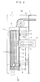
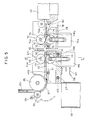
- a printer body 1 is provided on its outer surface with a recess 2 in which a leader stocker 3 is housed.
- the leader stocker 3 is in the form of a rectangular cylinder having on both sides thereof a plurality of pairs of grooves 4 spaced equally from each other to receive leaders.
- a pair of claws 5 are mounted at the bottom of each groove 4 (Fig. 3).
- Each claw 5 is supported pivotably around a pin 6.
- the claws 5 are pivoted upward urged by the leader L.
- they are pivoted downwardly by their own weight so that they will support the bottom end of the leader L.
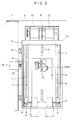
- a rear plate 7 of the leader stocker 3 is formed with an opening 9 and has a plurality of engaging pins 8. With the leaders L set in the grooves 4, the leader stocker 3 is detachably mounted in a stocker holder 10 which is provided in the recess 2.
- the stocker holder 10 is in the form of a plate and formed with guitar-shaped engaging holes 11. By bringing the engaging pins 8 into engagement with the engaging holes 11, the leader stocker 3 is detachably mounted.
- a side plate 12 which is supported so as to be movable along a rail 13 which is provided at one side of the recess 2.
- a rack 14 On the side plate 12 of the stocker holder 10 is mounted a rack 14 to be parallel to the rail 13. A pinion 15 meshes the rack 14 and is driven by a motor 16.
- a sprocket arm 17 On the front side of the recess 2 in the printer body 1 is provided a sprocket arm 17 having on one end a sprocket 19 which is driven by a motor 18. Part of the outer periphery of the sprocket 19 projects into the leader stocker 3 through a window 20 formed in the stocker holder 10 and the opening 9 of the leader stocker 3, so that the sprocket 19 will be engageable with square holes H formed in the leader L set in the leader stocker 3.
- the leader L set in the leader stocker 3 is discharged from the top of the leader stocker 3 by the rotation of the sprocket 19.
- the pinion 15 will be driven by the motor 16 to move the stocker holder 12 rightward in Fig. 2.
- the motor 18 will stop. Now the square holes H of the next leader L are in position for engagement with the sprocket 19.
- the leader L fed out of the leader stocker 3, is carried along a leader transfer path 21 provided in the printer body 1 and fed to a leader discharge path 78.
- the developed film is fed to a negative carrier 22 aligned with an exposure axis X.
- the negative carrier 22 is formed with an exposure window 23 and a film path 24.
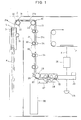
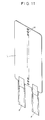
- the image on each image frame of the film F inserted in the film path 24 is, as shown in Fig. 1, illuminated by a light source 25 provided under the negative carrier 22 and printed on a printing paper P through a lens 26.
- a guide block 27 At the film inlet side of the negative carrier 22 is provided a guide block 27.
- a table 28 is provided between the guide block 27 and the negative carrier 22.
- the leader transfer path 21 from the leader stocker 3 to the guide block 27 includes a first transfer path 21a which feeds upward the leader L from the leader stocker 3, a second transfer path 21b extending in a lateral direction from the first transfer path 21a, and a third transfer path 21c extending vertically from the second transfer path 21b.
- a plurality of feed units 30 are provided to feed the leader L and the films F to the guide block 27.
- the feed units 30 comprises a plurality of rotary members 33 each having a sprocket 31 engageable with square holes H of the leader L, and a roller 32 coaxially provided with the sprocket 31 for guiding the movement of the film F.
- the rotary members 33 are spaced apart from each other with a distance smaller than the length of the leader L.
- press rollers 34 are brought into contact with the roller 32 in the rotary members 33 so that each rotary member 33 will rotate in one direction driven by a driving unit (not shown).
- the leader L fed downward along the third transfer path 21c, is changed its feed direction by 90 by a turn roller 35 and supplied to the guide block 27.
- the turn roller 35 rotates in one direction driven by a driving unit (not shown).
- the turn roller 35 has, on its one side for guiding the leader L, a guide roller 36 and an arcuate leader guide 37 to introduce the leader L along the outer surface of the turn roller 35. Further, a film stocker 38 is provided under the turn roller 35.
- the upper portion of the leader guide 37 is pivotably supported around a pin 39.
- the leader guide 37 pivots around the pin 39 by means of a pivot mechanism (not shown).
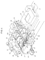
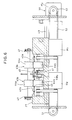
- Figs. 4 - 6 show the guide block 27 and the table 28 in more detail.
- the guide block 27 is formed on its top with a film guide 40 which is elastically supported by a spring 41.
- the film guide 40 includes film passages 42a and 42b extending toward the table 28. The distance between the film passages 42a and 42b is the same as that between the two films F attached to the leader (Fig. 4).
- the films F fed in the film passages 42a and 42b are carried toward the table 28 by film feed units 43a and 43b, respectively.
- the film feed units 43a and 43b each have a pair of film feed rollers 44a and 44b on its top and bottom.
- the lower feed rollers 44b have their top surfaces protruding from windows 45 which are formed on the bottom faces of the film passages 42a and 42b, and are separately rotated by motors M1 and M2, respectively, mounted in the guide block 27 (Fig. 5).
- the upper film feed rollers 44a are rotatably supported by a roller shaft 46, which has both ends thereof supported by a pair of bearings 47 mounted on both ends of the top face of the guide block 27 so as to be movable vertically.
- a spring 48 is provided for each of the bearings 47 to urge the roller shaft 46 downward so that the upper film feed rollers 44a will be pressed against the lower film feed rollers 44b.
- a limit switch SW1 is mounted on the guide block 27 upstream of the film feed units 43a and 43b to detect the tip of the leader L (Fig. 5). When the tip of the leader L abuts the limit switch SW1 to switch it on, the pivot mechanism for the leader guide 37 will activate to move the leader guide 37 away from the turn roller 35.
- the guide block 27 is supported so as to be movable along two guide rods 49, which extend in a direction perpendicular to the film passages 42a and 42b.
- the guide block 27 is moved along the guide rods 49, activated by a transfer unit 50.
- the transfer unit 50 comprises a pair of pulleys 51 and 52 and a timing belt 53 provided therearound (Fig. 4).
- the pulley 52 is rotated by a motor M3.
- Part of the timing belt 53 is fixed to the bottom face of the guide block 27.
- the cutter device 60 Between the guide block 27 and the table 28 is provided a cutter device 60 to cut off the films F from the leader L.
- the cutter device 60 comprises a lower blade 61 fixed to the front of the guide block 27 and an upper blade 62 which is vertically movable (Fig. 5).
- the table 28 is formed on its top with a film guide 70 which is elastically supported by a spring 71.
- the film guide 70 includes two film passages 72 extending toward the negative carrier 22. One of the film passages 72 is aligned with the film path 24 in the negative carrier 22.
- the distance between the film passages 72 is the same as that between the two film passages 42a and 42b formed on the film guide 40 on the guide block 27.
- a transfer unit 73 for feeding the film F to the negative carrier 22 is provided for each of the film passages 72 (Fig. 5).
- the transfer units 73 each have a pair of film feed rollers 74a and 74b arranged one on the other.
- the lower film feed rollers 74b are rotated by means of a motor M4.
- the upper feed rollers 74a are rotatably supported on a roller shaft 75, which has both ends thereof supported by a pair of bearings 76 mounted on both ends of the top face of the table 28 so as to be movable vertically.
- a spring 77 is provided for each of the bearings 76 to urge the roller shaft 75 downward so that the upper film feed rollers 74a will be pressed against the lower film feed rollers 74b.
- a limit switch SW2 is mounted ahead of the transfer units 73 and is turned on when the tip of the leader L abuts it.
- a leader guide 79 has its front end fixed by a shaft 80 which is rotatably supported by a table 28 so as to be turnable by a limited angle by means of a motor M5 or solenoid (not shown).
- a motor M5 or solenoid not shown.
- the leader L in the leader stocker 3 is fed up by the rotation of the sprocket 19, and then along the leader transfer path 21 by means of the feed unit 30.
- the leader guide 37 Since the leader guide 37 is in position along the outer surface of the turn roller 35, the leader L travels along the turn roller 35 guided by the leader guide 37, and changes its direction by 90°.
- the leader L then travels further along the film guide 40 formed on the top of the guide block 27. While moving, the film guide 40 sinks against the bias of the spring 41.
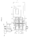
- the leader L is fed further by the film feed units 43a and 43b toward the table 28. As shown in Fig. 7, if the limit switch SW1 is activated by the tip of the leader, the leader guide 37 will pivot around the pin 39 away from the turn roller 35.
- the leader L is fed from the film guide 40 formed on the guide block 27 to the film guide 70 on the table 28. While travelling, the film guide 70 sinks against the bias of the spring 71. The leader L is moved further by the transfer units 73 provided on the film passage 72 of the film guide 70.
- the leader L is guided to a leader discharge path 78 (Fig. 5).
- the film feed units 43a and 43b and the transfer units 73 will stop.
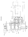
- the film guide 40 on the guide block 27 moves upward, bringing the film F into engagement with the film passages 42a and 42b.
- the cutter device 60 is activated to cut off the films F.
- the transfer unit 73 feeds the leader L at a high speed.
- the leader guide 79 will pivot downward until its upper face becomes horizontal. Further, the film guide 70 on the table guide 28 will move upward and be kept at the same level as the film guide 40 of the guide block 27.
- the feed speed of the transfer unit 73 returns to normal.
- the film feed unit 43a in the film passage 42a which is aligned with the film path 24 in the negative carrier 22 will operate to feed one of the films F to the negative carrier 22 (Fig. 9).
- the film feed unit 43b in the other film passage 42b halts its operation.
- the film F whose front end is in the film passage 42b has its rear end hanging down in the film stocker 38 by means of the feed unit 30.
- the guide block 27 travels along the guide rod 49, driven by the transfer unit 50.
- the transfer unit 50 will halt its operation.
- the other film F having its front end fitted in the other film passage 42b is fed toward the negative carrier 22.
- the next leader L is fed from the leader stocker 3 to the leader transfer path 21. The same operation is then repeated.
- the leader L accommodated in the leader stocker 3 is automatically fed to the leader transfer path 21, but it may be supplied by hand.
Landscapes
- Physics & Mathematics (AREA)
- General Physics & Mathematics (AREA)
- Photographic Developing Apparatuses (AREA)
- Projection-Type Copiers In General (AREA)
- Photographic Processing Devices Using Wet Methods (AREA)
Claims (1)
- Dispositif d'alimentation en film à utiliser dans un appareil d'impression de film, destiné à acheminer des films (F) fixés à une amorce (2) vers un support négatif (22) prévu le long d'un axe d'exposition (X), ledit dispositif d'alimentation en film comprenant un bloc de guidage (27) placé au niveau d'une face d'entrée de film dudit support négatif et formé sur sa partie supérieure, deux passages de film (42a, 42b) s'étendant vers ledit support négatif, une pluralité d'unités d'acheminement (30) pour acheminer les films reliés à l'amorce vers ledit bloc de guidage, un dispositif de coupe (60) pour couper les films de l'amorce quand l'extrémité arrière de l'amorce a passé ledit bloc de guidage, des moyens de décharge d'amorce (78, 79) pour décharger l'amorce coupée des films à partir d'une piste de film, des moyens d'acheminement de film (73) pour acheminer le film dudit passage de film audit support négatif, et des moyens de transfert (50) pour déplacer ledit bloc de guidage dans une direction perpendiculaire à la direction d'acheminement du film, afin d'aligner un desdits deux passages de film avec ladite entrée de film dudit support négatif.
Applications Claiming Priority (2)
| Application Number | Priority Date | Filing Date | Title |
|---|---|---|---|
| JP13427793A JP3182980B2 (ja) | 1993-06-04 | 1993-06-04 | 写真焼付機のフイルム供給装置 |
| JP134277/93 | 1993-06-04 |
Publications (2)
| Publication Number | Publication Date |
|---|---|
| EP0628872A1 EP0628872A1 (fr) | 1994-12-14 |
| EP0628872B1 true EP0628872B1 (fr) | 1997-12-17 |
Family
ID=15124524
Family Applications (1)
| Application Number | Title | Priority Date | Filing Date |
|---|---|---|---|
| EP94108384A Expired - Lifetime EP0628872B1 (fr) | 1993-06-04 | 1994-05-31 | Dispositif d'alimentation de film |
Country Status (7)
| Country | Link |
|---|---|
| US (1) | US5402206A (fr) |
| EP (1) | EP0628872B1 (fr) |
| JP (1) | JP3182980B2 (fr) |
| KR (1) | KR0169524B1 (fr) |
| CN (1) | CN1033536C (fr) |
| CA (1) | CA2124658C (fr) |
| DE (1) | DE69407347T2 (fr) |
Families Citing this family (4)
| Publication number | Priority date | Publication date | Assignee | Title |
|---|---|---|---|---|
| JP3611186B2 (ja) * | 1999-05-17 | 2005-01-19 | ノーリツ鋼機株式会社 | フィルム供給装置 |
| JP2005030944A (ja) * | 2003-07-07 | 2005-02-03 | Noritsu Koki Co Ltd | 測色装置 |
| CN102279512B (zh) * | 2011-05-17 | 2013-04-17 | 天津爱安特科技股份有限公司 | 一种缩微胶片摄影机的精准控制胶片行进装置 |
| KR101532328B1 (ko) * | 2013-09-30 | 2015-06-30 | 엘아이지인베니아 주식회사 | 초박막 평판표시장치 제조용 봉지필름의 클리닝 장치 |
Family Cites Families (6)
| Publication number | Priority date | Publication date | Assignee | Title |
|---|---|---|---|---|
| EP0251338B1 (fr) * | 1984-03-13 | 1992-08-05 | Fuji Photo Film Co., Ltd. | Accumulateur de film pour appareil de développement |
| US4774553A (en) * | 1987-11-19 | 1988-09-27 | Eastman Kodak Company | Film handling mechanism |
| JPH01204040A (ja) * | 1988-02-10 | 1989-08-16 | Fuji Photo Film Co Ltd | 分割プリントの境界表示装置 |
| US5097292A (en) * | 1989-05-31 | 1992-03-17 | Ray Hicks | Film drive system for photographic printers |
| US5153639A (en) * | 1991-02-07 | 1992-10-06 | Fuji Photo Film Co., Ltd. | Film supplying apparatus |
| US5289232A (en) * | 1992-01-09 | 1994-02-22 | Fuji Photo Film Co., Ltd. | Negative film supplying device |
-
1993
- 1993-06-04 JP JP13427793A patent/JP3182980B2/ja not_active Expired - Fee Related
-
1994
- 1994-05-30 CA CA002124658A patent/CA2124658C/fr not_active Expired - Fee Related
- 1994-05-31 DE DE69407347T patent/DE69407347T2/de not_active Expired - Fee Related
- 1994-05-31 EP EP94108384A patent/EP0628872B1/fr not_active Expired - Lifetime
- 1994-06-03 US US08/253,306 patent/US5402206A/en not_active Expired - Fee Related
- 1994-06-03 CN CN94108858A patent/CN1033536C/zh not_active Expired - Fee Related
- 1994-06-03 KR KR1019940012523A patent/KR0169524B1/ko not_active IP Right Cessation
Also Published As
| Publication number | Publication date |
|---|---|
| EP0628872A1 (fr) | 1994-12-14 |
| DE69407347D1 (de) | 1998-01-29 |
| CN1102483A (zh) | 1995-05-10 |
| KR950001400A (ko) | 1995-01-03 |
| JP3182980B2 (ja) | 2001-07-03 |
| KR0169524B1 (ko) | 1999-01-15 |
| US5402206A (en) | 1995-03-28 |
| JPH06347910A (ja) | 1994-12-22 |
| CA2124658C (fr) | 1999-01-05 |
| CN1033536C (zh) | 1996-12-11 |
| DE69407347T2 (de) | 1998-04-16 |
Similar Documents
| Publication | Publication Date | Title |
|---|---|---|
| US4791456A (en) | Photographic printer apparatus | |
| EP0628872B1 (fr) | Dispositif d'alimentation de film | |
| US5100251A (en) | Paper tractor mechanism | |
| EP0643324B1 (fr) | Appareil de traitement photographique | |
| US20030177880A1 (en) | Cutter system for multi size photographic prints | |
| JPH02189539A (ja) | 写真プリンター装置 | |
| US4469438A (en) | Print mask switching device | |
| US4397532A (en) | Film editing device | |
| US4518241A (en) | Installation for supplying photographic emulsion carriers to a developing machine | |
| US4595283A (en) | Apparatus and method for advancing photographic print paper | |
| CA2131941C (fr) | Machine de developpement photographique | |
| JPS63279240A (ja) | 写真焼付用マスク装置 | |
| JP3663821B2 (ja) | 感光材料搬送装置 | |
| JP2703130B2 (ja) | 写真プリントの受け渡し装置 | |
| JP2537695Y2 (ja) | 原板フィルムのパンチ・カット装置 | |
| JP2679891B2 (ja) | フィルム貼り込み装置 | |
| JPS6340133A (ja) | 焼付マスク駆動機構 | |
| JPH0719032B2 (ja) | 写真焼付用マスク装置 | |
| JPS63138332A (ja) | 写真焼付用マスク装置 | |
| JPS6239192A (ja) | 帯状感光材料切断装置 | |
| WO1990008341A1 (fr) | Dispositif de traitement photographique | |
| JPS6340132A (ja) | 写真焼付装置 | |
| JPH04367857A (ja) | ネガシートの切断装置 | |
| JPH0450157B2 (fr) | ||
| JPS63138330A (ja) | 写真焼付用マスク装置 |
Legal Events
| Date | Code | Title | Description |
|---|---|---|---|
| PUAI | Public reference made under article 153(3) epc to a published international application that has entered the european phase |
Free format text: ORIGINAL CODE: 0009012 |
|
| AK | Designated contracting states |
Kind code of ref document: A1 Designated state(s): CH DE FR GB IT LI |
|
| 17P | Request for examination filed |
Effective date: 19950426 |
|
| GRAG | Despatch of communication of intention to grant |
Free format text: ORIGINAL CODE: EPIDOS AGRA |
|
| 17Q | First examination report despatched |
Effective date: 19970225 |
|
| GRAG | Despatch of communication of intention to grant |
Free format text: ORIGINAL CODE: EPIDOS AGRA |
|
| GRAH | Despatch of communication of intention to grant a patent |
Free format text: ORIGINAL CODE: EPIDOS IGRA |
|
| GRAH | Despatch of communication of intention to grant a patent |
Free format text: ORIGINAL CODE: EPIDOS IGRA |
|
| GRAA | (expected) grant |
Free format text: ORIGINAL CODE: 0009210 |
|
| AK | Designated contracting states |
Kind code of ref document: B1 Designated state(s): CH DE FR GB IT LI |
|
| REG | Reference to a national code |
Ref country code: CH Ref legal event code: NV Representative=s name: PATENTANWALTSBUERO JEAN HUNZIKER Ref country code: CH Ref legal event code: EP |
|
| REF | Corresponds to: |
Ref document number: 69407347 Country of ref document: DE Date of ref document: 19980129 |
|
| ITF | It: translation for a ep patent filed | ||
| ET | Fr: translation filed | ||
| PLBE | No opposition filed within time limit |
Free format text: ORIGINAL CODE: 0009261 |
|
| STAA | Information on the status of an ep patent application or granted ep patent |
Free format text: STATUS: NO OPPOSITION FILED WITHIN TIME LIMIT |
|
| 26N | No opposition filed | ||
| PGFP | Annual fee paid to national office [announced via postgrant information from national office to epo] |
Ref country code: FR Payment date: 19990511 Year of fee payment: 6 |
|
| PGFP | Annual fee paid to national office [announced via postgrant information from national office to epo] |
Ref country code: GB Payment date: 19990526 Year of fee payment: 6 Ref country code: CH Payment date: 19990526 Year of fee payment: 6 |
|
| PGFP | Annual fee paid to national office [announced via postgrant information from national office to epo] |
Ref country code: DE Payment date: 19990528 Year of fee payment: 6 |
|
| PG25 | Lapsed in a contracting state [announced via postgrant information from national office to epo] |
Ref country code: LI Free format text: LAPSE BECAUSE OF NON-PAYMENT OF DUE FEES Effective date: 20000531 Ref country code: GB Free format text: LAPSE BECAUSE OF NON-PAYMENT OF DUE FEES Effective date: 20000531 Ref country code: CH Free format text: LAPSE BECAUSE OF NON-PAYMENT OF DUE FEES Effective date: 20000531 |
|
| REG | Reference to a national code |
Ref country code: CH Ref legal event code: PL |
|
| GBPC | Gb: european patent ceased through non-payment of renewal fee |
Effective date: 20000531 |
|
| PG25 | Lapsed in a contracting state [announced via postgrant information from national office to epo] |
Ref country code: FR Free format text: LAPSE BECAUSE OF NON-PAYMENT OF DUE FEES Effective date: 20010131 |
|
| PG25 | Lapsed in a contracting state [announced via postgrant information from national office to epo] |
Ref country code: DE Free format text: LAPSE BECAUSE OF NON-PAYMENT OF DUE FEES Effective date: 20010301 |
|
| REG | Reference to a national code |
Ref country code: FR Ref legal event code: ST |
|
| PG25 | Lapsed in a contracting state [announced via postgrant information from national office to epo] |
Ref country code: IT Free format text: LAPSE BECAUSE OF NON-PAYMENT OF DUE FEES;WARNING: LAPSES OF ITALIAN PATENTS WITH EFFECTIVE DATE BEFORE 2007 MAY HAVE OCCURRED AT ANY TIME BEFORE 2007. THE CORRECT EFFECTIVE DATE MAY BE DIFFERENT FROM THE ONE RECORDED. Effective date: 20050531 |