EP0628734B1 - Dispositif de fixation pour relier de manière amovible un tube polygonal, en particulier un tube à profil rectangulaire - Google Patents
Dispositif de fixation pour relier de manière amovible un tube polygonal, en particulier un tube à profil rectangulaire Download PDFInfo
- Publication number
- EP0628734B1 EP0628734B1 EP94108904A EP94108904A EP0628734B1 EP 0628734 B1 EP0628734 B1 EP 0628734B1 EP 94108904 A EP94108904 A EP 94108904A EP 94108904 A EP94108904 A EP 94108904A EP 0628734 B1 EP0628734 B1 EP 0628734B1
- Authority
- EP
- European Patent Office
- Prior art keywords
- fastening element
- tube
- elements
- spreader elements
- element according
- Prior art date
- Legal status (The legal status is an assumption and is not a legal conclusion. Google has not performed a legal analysis and makes no representation as to the accuracy of the status listed.)
- Expired - Lifetime
Links
- 230000001154 acute effect Effects 0.000 claims description 13
- 238000006073 displacement reaction Methods 0.000 claims description 4
- 239000002184 metal Substances 0.000 claims description 4
- 230000007704 transition Effects 0.000 claims description 3
- 239000000470 constituent Substances 0.000 claims 1
- 238000010276 construction Methods 0.000 description 3
- 230000000694 effects Effects 0.000 description 3
- 210000000078 claw Anatomy 0.000 description 2
- 238000004519 manufacturing process Methods 0.000 description 2
- 239000000463 material Substances 0.000 description 2
- 229910000639 Spring steel Inorganic materials 0.000 description 1
- 230000015572 biosynthetic process Effects 0.000 description 1
- 238000009434 installation Methods 0.000 description 1
- 230000035515 penetration Effects 0.000 description 1
Images

Classifications
-
- F—MECHANICAL ENGINEERING; LIGHTING; HEATING; WEAPONS; BLASTING
- F16—ENGINEERING ELEMENTS AND UNITS; GENERAL MEASURES FOR PRODUCING AND MAINTAINING EFFECTIVE FUNCTIONING OF MACHINES OR INSTALLATIONS; THERMAL INSULATION IN GENERAL
- F16B—DEVICES FOR FASTENING OR SECURING CONSTRUCTIONAL ELEMENTS OR MACHINE PARTS TOGETHER, e.g. NAILS, BOLTS, CIRCLIPS, CLAMPS, CLIPS OR WEDGES; JOINTS OR JOINTING
- F16B7/00—Connections of rods or tubes, e.g. of non-circular section, mutually, including resilient connections
- F16B7/02—Connections of rods or tubes, e.g. of non-circular section, mutually, including resilient connections with conical parts
- F16B7/025—Connections of rods or tubes, e.g. of non-circular section, mutually, including resilient connections with conical parts with the expansion of an element inside the tubes due to axial movement towards a wedge or conical element
-
- E—FIXED CONSTRUCTIONS
- E04—BUILDING
- E04B—GENERAL BUILDING CONSTRUCTIONS; WALLS, e.g. PARTITIONS; ROOFS; FLOORS; CEILINGS; INSULATION OR OTHER PROTECTION OF BUILDINGS
- E04B1/00—Constructions in general; Structures which are not restricted either to walls, e.g. partitions, or floors or ceilings or roofs
- E04B1/38—Connections for building structures in general
- E04B1/58—Connections for building structures in general of bar-shaped building elements
- E04B1/5825—Connections for building structures in general of bar-shaped building elements with a closed cross-section
- E04B1/5831—Connections for building structures in general of bar-shaped building elements with a closed cross-section of substantially rectangular form
-
- F—MECHANICAL ENGINEERING; LIGHTING; HEATING; WEAPONS; BLASTING
- F16—ENGINEERING ELEMENTS AND UNITS; GENERAL MEASURES FOR PRODUCING AND MAINTAINING EFFECTIVE FUNCTIONING OF MACHINES OR INSTALLATIONS; THERMAL INSULATION IN GENERAL
- F16B—DEVICES FOR FASTENING OR SECURING CONSTRUCTIONAL ELEMENTS OR MACHINE PARTS TOGETHER, e.g. NAILS, BOLTS, CIRCLIPS, CLAMPS, CLIPS OR WEDGES; JOINTS OR JOINTING
- F16B12/00—Jointing of furniture or the like, e.g. hidden from exterior
- F16B12/40—Joints for furniture tubing
-
- E—FIXED CONSTRUCTIONS
- E04—BUILDING
- E04B—GENERAL BUILDING CONSTRUCTIONS; WALLS, e.g. PARTITIONS; ROOFS; FLOORS; CEILINGS; INSULATION OR OTHER PROTECTION OF BUILDINGS
- E04B1/00—Constructions in general; Structures which are not restricted either to walls, e.g. partitions, or floors or ceilings or roofs
- E04B1/18—Structures comprising elongated load-supporting parts, e.g. columns, girders, skeletons
- E04B1/24—Structures comprising elongated load-supporting parts, e.g. columns, girders, skeletons the supporting parts consisting of metal
- E04B1/2403—Connection details of the elongated load-supporting parts
- E04B2001/2406—Connection nodes
-
- E—FIXED CONSTRUCTIONS
- E04—BUILDING
- E04B—GENERAL BUILDING CONSTRUCTIONS; WALLS, e.g. PARTITIONS; ROOFS; FLOORS; CEILINGS; INSULATION OR OTHER PROTECTION OF BUILDINGS
- E04B1/00—Constructions in general; Structures which are not restricted either to walls, e.g. partitions, or floors or ceilings or roofs
- E04B1/38—Connections for building structures in general
- E04B1/58—Connections for building structures in general of bar-shaped building elements
- E04B1/5825—Connections for building structures in general of bar-shaped building elements with a closed cross-section
- E04B2001/5856—Connections for building structures in general of bar-shaped building elements with a closed cross-section using the innerside thereof
-
- F—MECHANICAL ENGINEERING; LIGHTING; HEATING; WEAPONS; BLASTING
- F16—ENGINEERING ELEMENTS AND UNITS; GENERAL MEASURES FOR PRODUCING AND MAINTAINING EFFECTIVE FUNCTIONING OF MACHINES OR INSTALLATIONS; THERMAL INSULATION IN GENERAL
- F16B—DEVICES FOR FASTENING OR SECURING CONSTRUCTIONAL ELEMENTS OR MACHINE PARTS TOGETHER, e.g. NAILS, BOLTS, CIRCLIPS, CLAMPS, CLIPS OR WEDGES; JOINTS OR JOINTING
- F16B13/00—Dowels or other devices fastened in walls or the like by inserting them in holes made therein for that purpose
- F16B13/04—Dowels or other devices fastened in walls or the like by inserting them in holes made therein for that purpose with parts gripping in the hole or behind the reverse side of the wall after inserting from the front
-
- F—MECHANICAL ENGINEERING; LIGHTING; HEATING; WEAPONS; BLASTING
- F16—ENGINEERING ELEMENTS AND UNITS; GENERAL MEASURES FOR PRODUCING AND MAINTAINING EFFECTIVE FUNCTIONING OF MACHINES OR INSTALLATIONS; THERMAL INSULATION IN GENERAL
- F16B—DEVICES FOR FASTENING OR SECURING CONSTRUCTIONAL ELEMENTS OR MACHINE PARTS TOGETHER, e.g. NAILS, BOLTS, CIRCLIPS, CLAMPS, CLIPS OR WEDGES; JOINTS OR JOINTING
- F16B7/00—Connections of rods or tubes, e.g. of non-circular section, mutually, including resilient connections
- F16B7/04—Clamping or clipping connections
- F16B7/044—Clamping or clipping connections for rods or tubes being in angled relationship
- F16B7/0446—Clamping or clipping connections for rods or tubes being in angled relationship for tubes using the innerside thereof
Definitions
- the invention relates to a fastener for releasable connection a polygonal tube, preferably a square tube, with a base body that can be inserted into the end of the polygonal tube, are arranged on the expansion elements, which are characterized by External actuation by axial displacement relative to Spread the base body against the inner surfaces of the polygonal tube, around the base body and the polygonal tube connect to.
- Bracket-like expansion elements are due to an axial relative movement to the base body spread out and with their tips in a frictional connection brought with the inner walls of the hollow profiles. Due to the Forces occurring can very easily bulge out Inner walls come.
- DE-AS 32 49 169 Another type of fastener is in DE-AS 32 49 169 described, which the fasteners of the generic type due to the possibility of axial relative movement between the base body and spreading element ascribes only limited holding forces. For this reason DE-AS 21 49 169 discloses only radially movable pressure pieces. These fasteners are in the pipe socket of an inner tube arranged, in which slots are formed. The only radial Movable pressure pieces reach through these slots and lean against them their front edges. At the same time it is on the inner tube pushed outer tube exerted a radial pressure, causing the connection will be produced.
- FR 2 562 176 A1 is also a device for releasable Known to connect polygonal tubes, which consists of a cube, from which three stretchable guide pins extend at right angles, which are each composed of four expansion elements.
- conical screw element By tightening one arranged between the expansion elements, conical screw element in In the direction of the cube, the expansion elements are penetrated by the conical screw element pressed apart to form a non-positive To cause fixation.
- the generic Fasteners do not have an axial holding force Displacement of the expansion body relative to the base body, but by Penetration of the conical screw element caused.
- the invention has for its object to provide a fastener for releasably connecting a polygonal tube and preferably a square tube, with which a particularly high holding force can be achieved with a non-positive connection.
- the number of expansion elements is equal to the number of inner edges of the polygonal tube and the expansion elements are arranged on the base body so that they are spread only in the respective inner edges of the polygonal tube , and that the spreading elements are resilient and extend at an acute angle to the longitudinal axis of the polygonal tube.
- the number of expansion elements is also the same as the number of inner edges of the Polygonal tube is a distortion of the polygonal tube and thus the reduction the effective holding force due to changes in shape of the polygonal tube locked out. Rather, the spread of the spreading elements as a whole applied spreading force evenly in all inner edges of the polygonal tube, so that it keeps its shape in any case, even under very high ones Exposure to the expansion elements. With the proposed Fasteners can therefore be high even with low spreading forces achieve effective holding forces. This also helps that the expansion elements are resilient and inclined at an acute angle Extend the longitudinal axis of the polygonal tube so that the angle of attack Spreading elements counter the pull-out movement of a polygonal tube is directed.
- fastening element Spreading elements in the manner of resilient so that they are used for generation the spreading movement increase its acute angle of inclination. To this Wise becomes a particularly reliable fastener created.
- the base body at an acute angle has inclined to the longitudinal axis of the polygonal support surfaces on which slide the spreading elements along while spreading or de-spreading.
- the invention proposes that in not spread State of the acute angle of inclination of the expansion elements is less than that acute angle of inclination of the support surfaces, so that the expansion elements exclusively in the area of those formed at their outer ends Spreading tips rest on the support surfaces.
- Spreading elements with an axially acting in the direction of the support surfaces Commissioned force these can be in the area of their spreading tips Support surfaces slide outwards, where they then into one non-positive contact with the inner edges of the polygonal tube.
- all of the spreading elements Components of a one-piece, resilient expansion body, the over has a central area which is actuated by an actuating means, and from which the individual expansion elements over obtuse-angled Extend transitions radially outwards.
- the expansion body ensured that the applied by the individual expansion elements Spreading force evenly over the individual inner edges of the polygonal tube.
- each individual expansion element with the required expansion force it is not necessary each individual expansion element with the required expansion force to act upon. Rather, it is sufficient to use the spreading force, for example by means of a tension element on the central area of the expansion body. From there the spreads out Force evenly on the somewhat resilient expansion elements of the expansion body.
- the expansion body is preferably designed as a stamped part made of metal, the individual expansion elements by obtuse angles Bends of this stamped part are formed.
- the Spreading elements a section constant with respect to its width at the V-shaped pointed tips connect.
- the advantage of the spreading tips is that this is about establishing a positive connection out into the material of the polygonal tube in the manner of Incorporate claws and thus improve the connection even more.
- the actuation takes place the expansion elements via a centrally arranged in the base body Actuating means.
- the fastener according to the invention can be expanded significantly if according to a preferred one Design the fastener in addition to the base body has further, essentially identical basic bodies, these being orthogonal for fastening further polygonal tubes to each other on a preferably cube-shaped central body are arranged. In this way, one can single fastening element up to five such polygonal tubes fasten.
- the fastener is therefore suitable especially as a node element in the case of trusses that can be assembled Pipe constructions.
- the assembly of such constructions can be essential accelerate when the central body with a common actuator is provided with which the actuating means All actuate the base body at the same time.
- the central body with two, three, four or five basic bodies to accommodate multi-purpose pipes is.
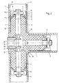
- the fastener shown in Fig. 1 only in partial representation serves a square tube, not shown in Fig. 1 made of metal and therefore with the fastener connect to.
- the one shown in FIG. block-like base body 1 in the end of the relevant square tube inserted and then by spreading a total of four arranged on the base body 1 spreading elements 2 non-positively connected to the square tube.
- the base body 1 is as block-shaped plastic body with a square cross section, this cross section is slightly smaller than the relevant internal cross section of the square tube to be connected.
- the train created by this is transferred to a star-shaped, metallic Spreading body 5 on which the individual in the form of rays Spreading elements 2 are formed.
- the square nut 4 of the actuator transmitted tensile force spreads the expansion body 5, so that the four expansion elements 2 be moved outwards.
- the spreading elements 2 are only in the area of there are a total of four edges of the base body 1, and only develop their spreading effect there. This leads to the fact that the plugged Square tube in the area of its four inner edges from the four expansion elements 2 are grasped and firmly held becomes.
- there is a certain positive locking added since the expansion elements 2 designed in a V-shape Spreading tips 6 leak, which are like claws in the Work in the material of the square tube.
- the square tube 7 to be fastened is first plugged onto the base body 1, which is provided in three ways, until the end faces of the corresponding paragraphs 8 of the fastener is applied.
- the respective actuating means in the form of the screw 3 with the square nut 4 is loose here.
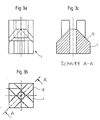
- the expansion tips 6 of the expansion body 5 of the respective expansion element 2 do not protrude beyond the cross-sectional area of the base body 1, since the metal expansion body 5 is designed as a spring as a whole, as illustrated in FIG. 2.
- the expansion body 5 consists of a suitable spring steel and has a flat, central area 9 on which the underside of the square nut 4 lies flat.
- the individual expansion elements 2 extend from this central area 9 of the expansion body 5 in the direction of the outer edges 10 of the base body 1 or the inner edges 11 of the square tube 7 located there.
- the transition between the central area 9 and the expansion elements 2 is in each case by a obtuse-angled bend formed.
- the spreading elements 2 are oriented at an acute angle w 1 to the inner edges 11, as illustrated in FIG. 2.
- Fig. 2 also shows that each expansion element 2 is supported on an associated support surface 12 of the base body 1.
- This support surface 12 is also inclined at an acute angle w 2 to the respective inner edge 11 of the square tube 7.
- the angle of inclination w 2 of the support surface 12 is less than the angle of inclination w 1 of the associated spreading element 2, which, as can be clearly seen in FIG 12 of the base body 1 rests.
- the remaining areas of the expansion body 5 have a clear play compared to the correspondingly designed surfaces of the base body 1, as can be clearly seen in FIG. 2.
- Fig. 2 it is shown that in the embodiment as a whole three of the basic bodies 1 described are present. This are connected in one piece via a common central body 16.
- the central body 16 is cube-shaped, so that the individual base bodies 1 extend orthogonally therefrom. It is obvious that such a central body 16 is not can only accommodate three basic bodies 1, as is the case with the exemplary embodiment is the case, but any number Basic bodies between 1 and 5.
- the central body 16 of the fastener with an actuator 17 common to all base bodies 1 provided in the form of a screw insert 18.
- the screw insert 18 has a central opening 19 through which arranged in the opposite body 1 Can reach screw 3a.
- the screw insert 18 also has on the back via wedge surfaces 20, on which corresponding wedge surfaces 21 of screws 3b, which act as actuating means arranged orthogonally to said base body 1 Serve basic body.
- the base body and the expansion body are improved in such a way that between the expansion elements and the polygonal tube no point-like contact, but as large a surface as possible Touches occur. This will make the probability of Bulges reduced due to very high holding forces, so that overall higher holding forces are made possible.
- the in the Fig. 3a to 3c is a very simple structure, essentially made of a rectangular profile piece Body that has a central bore for receiving a screw insert and radially from the center to the corners Has support surfaces 12. The support surfaces are roughly in one An angle of 45 ° is shown, as the sectional view in FIG. 3c shows. which shows the section along the line A-A of Fig. 3b.
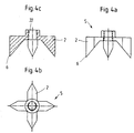
- FIGS. 4a to 4c show expanding body equipped.
- This is like a propeller provided with four expansion elements, one essentially have a triangular cross section.
- 4a shows a side view 4b is a top view and FIG. 4c a sectional view.
- the inclination of the inner surfaces of the expansion elements 2 is larger than that in the exemplary embodiment shown Inclination of the support surfaces 12 on the base body, for example 50 °.
- the radial outer edges of the expansion elements 2 are straight and the spreading elements 2 are towards the radial outer edges bevelled, for example with bevels of 30 ° each.
- the expansion body 5 has a threaded bore 22.
- the expansion body 5 in those shown in FIGS. 4a to 4c Execution is also extremely simple to set up and do in addition the use of an additional mother for the No need for a clamping screw. Due to the geometry of the Spreading elements 2 do not only come with the spreading tips 6 in connection with the inner edges of the polygonal tube, but over certain lengths of the radial outer edges. The holding forces thus spread over larger areas, so that even at larger holding forces bulges can be avoided.
- each have spreading elements 2 with spreading tips 6 are also columnar spreading elements conceivable.
- strand-like Spreading elements with an essentially triangular cross section be used that are columnar from an essentially that Internal cross section of the base plate corresponding to the polygonal tube stand out. The spreading elements then become spreading arms also over large edge areas on the inner edges of the Support polygonal tube.
Claims (10)
- Dispositif de fixation pour relier de manière amovible des tubes polygonaux, se composant d'au moins un tube polygonal, de préférence à profil rectangulaire, et d'un élément de fixation avec un corps principal insérable dans l'extrémité du tube polygonal, sur lequel sont disposés des éléments écarteurs qui s'écartent par actionnement de l'extérieur grâce à un décalage axial par rapport au corps principal contre les surfaces intérieures du tube polygonal afin de relier entre eux par adhérence le corps principal et le tube polygonal caractérisé en ce que
le nombre d'éléments écarteurs (2) est le même que le nombre des bords intérieurs (11) du tube polygonal (7) et que les éléments écarteurs (2) sont disposés sur le corps principal (1) de manière que, lorsqu'ils sont écartés, ils reposent uniquement sur les bords intérieurs respectifs (11) du tube polygonal (7) et que les éléments écarteurs (2) sont configurés comme des ressorts et s'évasent en formant un angle aigu (w1) incliné par rapport à l'axe longitudinal du tube polygonal (7). - Elément de fixation suivant la revendication 1, caractérisé en ce que les éléments de fixation (2) sont configurés comme des ressorts de manière qu'ils augmentent leur angle aigu d'inclinaison (w1) afin de générer un mouvement d'écartement.
- Elément de fixation suivant la revendication 1, caractérisé en ce que le corps principal (1) présente, sous un angle aigu (W2), par rapport à l'axe longitudinal du tube polygonal (7) des surfaces d'appui inclinées (12) le long lesquelles les éléments écarteurs (2) glissent pendant l'écartement ou le resserrement.
- Elément de fixation suivant la revendication 3, caractérisé en ce que lorsqu'il n'est pas en position écartée, l'angle aigu d'inclinaison (wl) des éléments écarteurs (2) est plus petit que l'angle aigu d'inclinaison (w2) des surfaces d'appui (12), de manière que les éléments de fixation (2) reposent sur les surfaces d'appui (12) exclusivement dans la zone des pointes d'écartement (6) formées à leurs extrémités extérieures.
- Elément de fixation suivant l'une des revendications 1 à 4, caractérisé en ce que tous les éléments écarteurs (2) font partie d'un corps écarteur (5) élastique monobloc qui présente une zone centrale (9) sur laquelle un élément d'actionnement (3, 3a, 3b) est en prise, et à partir duquel les différents éléments écarteurs (2) s'écartent vers l'extérieur en faisceau par le biais de transitions à angle obtus.
- Elément de fixation suivant la revendication 5, caractérisé en ce que l'élément écarteur (2) se présente sous forme de pièce estampée en métal et que les différents éléments écarteurs (2) sont formés par des pliures à angle obtus de cette pièce estampée.
- Elément de fixation suivant l'une des revendications 1 à 6, caractérisé en ce que les éléments écarteurs (2) présentent une section constante par rapport à sa largeur (14), sur laquelle se raccordent les pointes d'écartement (6) se terminant en forme de pointe en V.
- Elément de fixation suivant la revendication 1, caractérisé en ce que l'actionnement des éléments de fixation (2) se fait par un moyen d'actionnement (3, 3a, 3b) disposé au centre du corps principal.
- Elément de fixation suivant la revendication 1, caractérisé en ce que l'élément de fixation dispose en complément du corps principal (1) d'autres corps principaux (1) essentiellement identiques, ces derniers étant disposés orthogonalement les uns par rapport aux autres sur un corps central (16) de préférence de forme cubique, pour la fixation d'autres tubes polygonaux.
- Elément de fixation suivant la revendication 9, caractérisé en ce que le corps central (16) est muni d'un organe d'actionnement commun (17, 18) permettant d'actionner simultanément les moyens d'actionnement (3b) de plusieurs corps principaux (1).
Applications Claiming Priority (2)
| Application Number | Priority Date | Filing Date | Title |
|---|---|---|---|
| DE9308677U DE9308677U1 (de) | 1993-06-10 | 1993-06-10 | Befestigungselement zum lösbaren Verbinden eines Mehrkantrohres, vorzugsweise eines Vierkantrohres |
| DE9308677U | 1993-06-10 |
Publications (2)
| Publication Number | Publication Date |
|---|---|
| EP0628734A1 EP0628734A1 (fr) | 1994-12-14 |
| EP0628734B1 true EP0628734B1 (fr) | 1999-02-17 |
Family
ID=6894272
Family Applications (1)
| Application Number | Title | Priority Date | Filing Date |
|---|---|---|---|
| EP94108904A Expired - Lifetime EP0628734B1 (fr) | 1993-06-10 | 1994-06-10 | Dispositif de fixation pour relier de manière amovible un tube polygonal, en particulier un tube à profil rectangulaire |
Country Status (2)
| Country | Link |
|---|---|
| EP (1) | EP0628734B1 (fr) |
| DE (2) | DE9308677U1 (fr) |
Cited By (1)
| Publication number | Priority date | Publication date | Assignee | Title |
|---|---|---|---|---|
| IT202100009431A1 (it) * | 2021-04-14 | 2022-10-14 | Emmeallaenne S R L | Giunto di connessione |
Families Citing this family (9)
| Publication number | Priority date | Publication date | Assignee | Title |
|---|---|---|---|---|
| DE29505791U1 (de) * | 1995-04-04 | 1995-06-01 | Hestex Systems Bv | Befestigungselement zum lösbaren Verbinden eines Mehrkantrohres |
| AU709771B2 (en) * | 1995-09-28 | 1999-09-09 | Tjm Products Pty Ltd | A coupling system |
| IT1310997B1 (it) * | 1999-02-23 | 2002-02-27 | Angelo Odorico | Giunto di assemblaggio per telai di mobili. |
| ITMI20131868A1 (it) * | 2013-11-11 | 2015-05-12 | Eta Spa | Dispositivo di intergiunzione tra profilati |
| SE538241C2 (sv) * | 2014-05-07 | 2016-04-12 | Xylem Ip Man S À R L | Gejdrörssammansättning samt gejdrörshållare därför |
| US10781839B2 (en) * | 2016-10-05 | 2020-09-22 | Goodrich Corporation | Hybrid metallic/composite joint with enhanced strength |
| CN107559277B (zh) * | 2017-08-29 | 2019-12-03 | 浙江云洁仓储设备有限公司 | 一种用于横梁式货架承重杆的连接装置 |
| EP4187111A1 (fr) * | 2021-11-30 | 2023-05-31 | Airbus Operations GmbH | Agencement de verrouillage permettant de connecter et d'interverrouiller des barres au niveau d'un noeud à l'intérieur d'un treillis |
| CN114635504B (zh) * | 2022-04-13 | 2023-10-13 | 杭州潮峰重工钢结构有限公司 | 基于仿古建筑的装配式钢结构框架快装结构及其安装方法 |
Family Cites Families (9)
| Publication number | Priority date | Publication date | Assignee | Title |
|---|---|---|---|---|
| FR1042218A (fr) * | 1951-09-15 | 1953-10-29 | Fixation démontable pour objets tubulaires | |
| DE2130639A1 (de) * | 1971-06-21 | 1972-12-28 | Metallbau Koelble Gmbh | Eckverbindung,insbesondere fuer Fenster-,Tuerrahmen od.dgl. |
| DE2220738C2 (de) * | 1972-04-27 | 1974-08-22 | Veyhl-Produktion, 7261 Zwerenberg | Verbindung für die Rohre von Rahmengestellen |
| DE2349169C3 (de) * | 1973-09-29 | 1978-05-11 | Ewald 4600 Dortmund Rueter | Steckverbindung |
| DE2434524C2 (de) * | 1974-07-18 | 1982-12-16 | Ewald 4600 Dortmund Rüter | Steckverbindung zum Anschluß von Rohren |
| DE2615796A1 (de) * | 1976-04-10 | 1977-10-27 | Josef Serwe | Stabverbindungskonstruktion fuer ein hochbau-fachwerk |
| FR2549548B1 (fr) * | 1983-07-20 | 1987-01-30 | Descoings Joel | Dispositif de fixation de deux pieces allongees de construction bout a bout, notamment de deux pieces en bois |
| FR2562176B3 (fr) * | 1984-03-29 | 1986-07-18 | Applic Plastiques Equip Ele | Dispositif pour l'assemblage de barres profilees tubulaires, notamment pour la construction d'armoires electriques ou d'armoires industrielles |
| GB2264517A (en) * | 1992-01-31 | 1993-09-01 | Ergotrak Building Systems Ltd | Connector for e.g. building modules |
-
1993
- 1993-06-10 DE DE9308677U patent/DE9308677U1/de not_active Expired - Lifetime
-
1994
- 1994-06-10 EP EP94108904A patent/EP0628734B1/fr not_active Expired - Lifetime
- 1994-06-10 DE DE59407821T patent/DE59407821D1/de not_active Expired - Fee Related
Cited By (1)
| Publication number | Priority date | Publication date | Assignee | Title |
|---|---|---|---|---|
| IT202100009431A1 (it) * | 2021-04-14 | 2022-10-14 | Emmeallaenne S R L | Giunto di connessione |
Also Published As
| Publication number | Publication date |
|---|---|
| EP0628734A1 (fr) | 1994-12-14 |
| DE9308677U1 (de) | 1993-10-14 |
| DE59407821D1 (de) | 1999-03-25 |
Similar Documents
| Publication | Publication Date | Title |
|---|---|---|
| DE4401746C2 (de) | T Mutter | |
| EP3470691B1 (fr) | Cheville basculante | |
| DE4405240C2 (de) | Verbindungselement mit beidseitigem Gewinde | |
| DE1750969B1 (de) | Verbindungsvorrichtung zur verbindung rohrfoermiger teile | |
| EP1040544A1 (fr) | Cheville | |
| EP0628734B1 (fr) | Dispositif de fixation pour relier de manière amovible un tube polygonal, en particulier un tube à profil rectangulaire | |
| DE3523155A1 (de) | Verbindungselement fuer rohre | |
| DE3025660C2 (de) | Befestigungsvorrichtung | |
| EP2044341B1 (fr) | Écrou de blocage | |
| DE102015116421A1 (de) | Kippdübel | |
| EP0882898A1 (fr) | Dispositif d'ancrage | |
| DE3208347C1 (de) | Spreizdübel | |
| DE2452054B2 (de) | Quer zueinander stehendes Paar von Platten aus Holz, Holzspänen o.dgl. mit einer Verbindungsvorrichtung | |
| EP3054810B1 (fr) | Système de noeuds d'assemblage et kit d'assemblage | |
| DE4316808C2 (de) | Spannstück für Rohrelemente | |
| DE19546574A1 (de) | Schraube zum Befestigen von Dämmplatten an einer Unterkonstruktion | |
| AT524670B1 (de) | Dübel zum Verbinden von zwei Bauteilen | |
| DE19853988C1 (de) | Befestigungsvorrichtung | |
| AT394094B (de) | Formrohrverbindung | |
| DE2605169C3 (de) | Spreizklotz zum Festklemmen von Bauteilen in Rohren mit eckigem Querschnitt | |
| DE102022203736A1 (de) | Befestigungsvorrichtung, Anordnung mit einer Befestigungsvorrichtung und Verfahren zum Herstellen einer Befestigungsvorrichtung | |
| DE19754023A1 (de) | Befestigungsanordnung mit einem Dübel für ein metallisches Bauteil | |
| EP0646730A2 (fr) | Dispositif et son utilisation pour fixer un objet sur une paroi | |
| DE19639396A1 (de) | Kunststoffmutter zum Verbinden von plattenartigen Teilen | |
| DE102022110430A1 (de) | Bauteil und Verbindungselement für ein Möbelsystem |
Legal Events
| Date | Code | Title | Description |
|---|---|---|---|
| PUAI | Public reference made under article 153(3) epc to a published international application that has entered the european phase |
Free format text: ORIGINAL CODE: 0009012 |
|
| AK | Designated contracting states |
Kind code of ref document: A1 Designated state(s): DE FR GB IT SE |
|
| 17P | Request for examination filed |
Effective date: 19950613 |
|
| 17Q | First examination report despatched |
Effective date: 19961028 |
|
| GRAG | Despatch of communication of intention to grant |
Free format text: ORIGINAL CODE: EPIDOS AGRA |
|
| GRAG | Despatch of communication of intention to grant |
Free format text: ORIGINAL CODE: EPIDOS AGRA |
|
| GRAH | Despatch of communication of intention to grant a patent |
Free format text: ORIGINAL CODE: EPIDOS IGRA |
|
| GRAH | Despatch of communication of intention to grant a patent |
Free format text: ORIGINAL CODE: EPIDOS IGRA |
|
| GRAA | (expected) grant |
Free format text: ORIGINAL CODE: 0009210 |
|
| RAP3 | Party data changed (applicant data changed or rights of an application transferred) |
Owner name: HESTEX SYSTEMS B.V. |
|
| AK | Designated contracting states |
Kind code of ref document: B1 Designated state(s): DE FR GB IT SE |
|
| PG25 | Lapsed in a contracting state [announced via postgrant information from national office to epo] |
Ref country code: IT Free format text: LAPSE BECAUSE OF FAILURE TO SUBMIT A TRANSLATION OF THE DESCRIPTION OR TO PAY THE FEE WITHIN THE PRESCRIBED TIME-LIMIT;WARNING: LAPSES OF ITALIAN PATENTS WITH EFFECTIVE DATE BEFORE 2007 MAY HAVE OCCURRED AT ANY TIME BEFORE 2007. THE CORRECT EFFECTIVE DATE MAY BE DIFFERENT FROM THE ONE RECORDED. Effective date: 19990217 Ref country code: GB Free format text: LAPSE BECAUSE OF NON-PAYMENT OF DUE FEES Effective date: 19990217 Ref country code: FR Free format text: LAPSE BECAUSE OF FAILURE TO SUBMIT A TRANSLATION OF THE DESCRIPTION OR TO PAY THE FEE WITHIN THE PRESCRIBED TIME-LIMIT Effective date: 19990217 |
|
| REF | Corresponds to: |
Ref document number: 59407821 Country of ref document: DE Date of ref document: 19990325 |
|
| EN | Fr: translation not filed | ||
| GBV | Gb: ep patent (uk) treated as always having been void in accordance with gb section 77(7)/1977 [no translation filed] |
Effective date: 19990217 |
|
| PLBE | No opposition filed within time limit |
Free format text: ORIGINAL CODE: 0009261 |
|
| STAA | Information on the status of an ep patent application or granted ep patent |
Free format text: STATUS: NO OPPOSITION FILED WITHIN TIME LIMIT |
|
| 26N | No opposition filed | ||
| PGFP | Annual fee paid to national office [announced via postgrant information from national office to epo] |
Ref country code: SE Payment date: 20020531 Year of fee payment: 9 |
|
| PGFP | Annual fee paid to national office [announced via postgrant information from national office to epo] |
Ref country code: DE Payment date: 20020807 Year of fee payment: 9 |
|
| PG25 | Lapsed in a contracting state [announced via postgrant information from national office to epo] |
Ref country code: SE Free format text: LAPSE BECAUSE OF NON-PAYMENT OF DUE FEES Effective date: 20030611 |
|
| PG25 | Lapsed in a contracting state [announced via postgrant information from national office to epo] |
Ref country code: DE Free format text: LAPSE BECAUSE OF NON-PAYMENT OF DUE FEES Effective date: 20040101 |
|
| EUG | Se: european patent has lapsed |