EP0628376A1 - Elément chauffant électrique, ainsi que méthode de fabrication - Google Patents
Elément chauffant électrique, ainsi que méthode de fabrication Download PDFInfo
- Publication number
- EP0628376A1 EP0628376A1 EP94304127A EP94304127A EP0628376A1 EP 0628376 A1 EP0628376 A1 EP 0628376A1 EP 94304127 A EP94304127 A EP 94304127A EP 94304127 A EP94304127 A EP 94304127A EP 0628376 A1 EP0628376 A1 EP 0628376A1
- Authority
- EP
- European Patent Office
- Prior art keywords
- semiconductor
- metallic
- metallic element
- hole
- heater
- Prior art date
- Legal status (The legal status is an assumption and is not a legal conclusion. Google has not performed a legal analysis and makes no representation as to the accuracy of the status listed.)
- Granted
Links
- 239000004065 semiconductor Substances 0.000 title claims abstract description 128
- 238000000034 method Methods 0.000 title claims abstract description 77
- 229910052751 metal Inorganic materials 0.000 claims abstract description 79
- 239000000463 material Substances 0.000 claims abstract description 48
- 230000003647 oxidation Effects 0.000 claims abstract description 45
- 238000007254 oxidation reaction Methods 0.000 claims abstract description 45
- XUIMIQQOPSSXEZ-UHFFFAOYSA-N Silicon Chemical compound [Si] XUIMIQQOPSSXEZ-UHFFFAOYSA-N 0.000 claims abstract description 41
- 229910052710 silicon Inorganic materials 0.000 claims abstract description 40
- 239000010703 silicon Substances 0.000 claims abstract description 40
- PXHVJJICTQNCMI-UHFFFAOYSA-N Nickel Chemical compound [Ni] PXHVJJICTQNCMI-UHFFFAOYSA-N 0.000 claims abstract description 27
- 230000000391 smoking effect Effects 0.000 claims abstract description 15
- 239000007769 metal material Substances 0.000 claims abstract description 14
- JUZTWRXHHZRLED-UHFFFAOYSA-N [Si].[Cu].[Cu].[Cu].[Cu].[Cu] Chemical compound [Si].[Cu].[Cu].[Cu].[Cu].[Cu] JUZTWRXHHZRLED-UHFFFAOYSA-N 0.000 claims abstract description 13
- 229910021360 copper silicide Inorganic materials 0.000 claims abstract description 13
- 229910000881 Cu alloy Inorganic materials 0.000 claims abstract description 12
- 229910052802 copper Inorganic materials 0.000 claims abstract description 12
- 239000010949 copper Substances 0.000 claims abstract description 12
- 229910052759 nickel Inorganic materials 0.000 claims abstract description 12
- RYGMFSIKBFXOCR-UHFFFAOYSA-N Copper Chemical compound [Cu] RYGMFSIKBFXOCR-UHFFFAOYSA-N 0.000 claims abstract description 11
- 239000002184 metal Substances 0.000 claims description 40
- 229910021332 silicide Inorganic materials 0.000 claims description 21
- FVBUAEGBCNSCDD-UHFFFAOYSA-N silicide(4-) Chemical compound [Si-4] FVBUAEGBCNSCDD-UHFFFAOYSA-N 0.000 claims description 18
- 238000002844 melting Methods 0.000 claims description 13
- 230000008018 melting Effects 0.000 claims description 13
- 239000011888 foil Substances 0.000 claims description 8
- 239000012535 impurity Substances 0.000 claims description 6
- 238000004140 cleaning Methods 0.000 claims description 5
- XKRFYHLGVUSROY-UHFFFAOYSA-N Argon Chemical compound [Ar] XKRFYHLGVUSROY-UHFFFAOYSA-N 0.000 claims description 4
- IJGRMHOSHXDMSA-UHFFFAOYSA-N Atomic nitrogen Chemical compound N#N IJGRMHOSHXDMSA-UHFFFAOYSA-N 0.000 claims description 4
- 239000011261 inert gas Substances 0.000 claims description 4
- 229910052723 transition metal Inorganic materials 0.000 claims description 4
- 229910000906 Bronze Inorganic materials 0.000 claims description 3
- VYZAMTAEIAYCRO-UHFFFAOYSA-N Chromium Chemical compound [Cr] VYZAMTAEIAYCRO-UHFFFAOYSA-N 0.000 claims description 3
- ZOKXTWBITQBERF-UHFFFAOYSA-N Molybdenum Chemical compound [Mo] ZOKXTWBITQBERF-UHFFFAOYSA-N 0.000 claims description 3
- 229910000990 Ni alloy Inorganic materials 0.000 claims description 3
- RTAQQCXQSZGOHL-UHFFFAOYSA-N Titanium Chemical compound [Ti] RTAQQCXQSZGOHL-UHFFFAOYSA-N 0.000 claims description 3
- RIRXDDRGHVUXNJ-UHFFFAOYSA-N [Cu].[P] Chemical compound [Cu].[P] RIRXDDRGHVUXNJ-UHFFFAOYSA-N 0.000 claims description 3
- 229910052804 chromium Inorganic materials 0.000 claims description 3
- 239000011651 chromium Substances 0.000 claims description 3
- 239000004020 conductor Substances 0.000 claims description 3
- 229910052750 molybdenum Inorganic materials 0.000 claims description 3
- 239000011733 molybdenum Substances 0.000 claims description 3
- 229910052719 titanium Inorganic materials 0.000 claims description 3
- 239000010936 titanium Substances 0.000 claims description 3
- 229910052786 argon Inorganic materials 0.000 claims description 2
- BHEPBYXIRTUNPN-UHFFFAOYSA-N hydridophosphorus(.) (triplet) Chemical compound [PH] BHEPBYXIRTUNPN-UHFFFAOYSA-N 0.000 claims description 2
- 229910052757 nitrogen Inorganic materials 0.000 claims description 2
- 238000003631 wet chemical etching Methods 0.000 claims description 2
- 239000002019 doping agent Substances 0.000 claims 6
- 150000003624 transition metals Chemical class 0.000 claims 3
- 230000003213 activating effect Effects 0.000 claims 2
- 150000001875 compounds Chemical class 0.000 claims 2
- 150000002736 metal compounds Chemical class 0.000 claims 1
- 230000001681 protective effect Effects 0.000 abstract description 8
- 239000002210 silicon-based material Substances 0.000 abstract description 7
- 238000010438 heat treatment Methods 0.000 description 19
- 229910019655 synthetic inorganic crystalline material Inorganic materials 0.000 description 6
- 230000015556 catabolic process Effects 0.000 description 5
- 238000006731 degradation reaction Methods 0.000 description 5
- 241000208125 Nicotiana Species 0.000 description 4
- 235000002637 Nicotiana tabacum Nutrition 0.000 description 4
- 239000000155 melt Substances 0.000 description 4
- 229910001092 metal group alloy Inorganic materials 0.000 description 4
- 230000035882 stress Effects 0.000 description 4
- 238000001816 cooling Methods 0.000 description 3
- 239000000796 flavoring agent Substances 0.000 description 3
- 235000019634 flavors Nutrition 0.000 description 3
- 230000008646 thermal stress Effects 0.000 description 3
- XEEYBQQBJWHFJM-UHFFFAOYSA-N Iron Chemical compound [Fe] XEEYBQQBJWHFJM-UHFFFAOYSA-N 0.000 description 2
- 229910045601 alloy Inorganic materials 0.000 description 2
- 239000000956 alloy Substances 0.000 description 2
- 238000009835 boiling Methods 0.000 description 2
- 238000006243 chemical reaction Methods 0.000 description 2
- 238000005755 formation reaction Methods 0.000 description 2
- 150000002739 metals Chemical class 0.000 description 2
- 239000012768 molten material Substances 0.000 description 2
- 230000035515 penetration Effects 0.000 description 2
- 238000003825 pressing Methods 0.000 description 2
- 239000011241 protective layer Substances 0.000 description 2
- 238000007711 solidification Methods 0.000 description 2
- 230000008023 solidification Effects 0.000 description 2
- 238000003466 welding Methods 0.000 description 2
- 235000001674 Agaricus brunnescens Nutrition 0.000 description 1
- 229910000570 Cupronickel Inorganic materials 0.000 description 1
- 229910052779 Neodymium Inorganic materials 0.000 description 1
- ATJFFYVFTNAWJD-UHFFFAOYSA-N Tin Chemical compound [Sn] ATJFFYVFTNAWJD-UHFFFAOYSA-N 0.000 description 1
- 229910002065 alloy metal Inorganic materials 0.000 description 1
- 238000005275 alloying Methods 0.000 description 1
- JNDMLEXHDPKVFC-UHFFFAOYSA-N aluminum;oxygen(2-);yttrium(3+) Chemical compound [O-2].[O-2].[O-2].[Al+3].[Y+3] JNDMLEXHDPKVFC-UHFFFAOYSA-N 0.000 description 1
- 229910052787 antimony Inorganic materials 0.000 description 1
- WATWJIUSRGPENY-UHFFFAOYSA-N antimony atom Chemical compound [Sb] WATWJIUSRGPENY-UHFFFAOYSA-N 0.000 description 1
- QVGXLLKOCUKJST-UHFFFAOYSA-N atomic oxygen Chemical compound [O] QVGXLLKOCUKJST-UHFFFAOYSA-N 0.000 description 1
- 239000011324 bead Substances 0.000 description 1
- 230000015572 biosynthetic process Effects 0.000 description 1
- 239000011248 coating agent Substances 0.000 description 1
- 238000000576 coating method Methods 0.000 description 1
- 239000012141 concentrate Substances 0.000 description 1
- 239000000356 contaminant Substances 0.000 description 1
- YOCUPQPZWBBYIX-UHFFFAOYSA-N copper nickel Chemical compound [Ni].[Cu] YOCUPQPZWBBYIX-UHFFFAOYSA-N 0.000 description 1
- 229910021419 crystalline silicon Inorganic materials 0.000 description 1
- 230000002939 deleterious effect Effects 0.000 description 1
- 238000009792 diffusion process Methods 0.000 description 1
- 238000005553 drilling Methods 0.000 description 1
- -1 e.g. Chemical compound 0.000 description 1
- 239000012777 electrically insulating material Substances 0.000 description 1
- 238000005530 etching Methods 0.000 description 1
- 239000007789 gas Substances 0.000 description 1
- 229910052742 iron Inorganic materials 0.000 description 1
- 238000004093 laser heating Methods 0.000 description 1
- 239000010410 layer Substances 0.000 description 1
- 230000004807 localization Effects 0.000 description 1
- 230000013011 mating Effects 0.000 description 1
- 239000000289 melt material Substances 0.000 description 1
- 239000000203 mixture Substances 0.000 description 1
- QEFYFXOXNSNQGX-UHFFFAOYSA-N neodymium atom Chemical compound [Nd] QEFYFXOXNSNQGX-UHFFFAOYSA-N 0.000 description 1
- 229910000480 nickel oxide Inorganic materials 0.000 description 1
- GNRSAWUEBMWBQH-UHFFFAOYSA-N oxonickel Chemical compound [Ni]=O GNRSAWUEBMWBQH-UHFFFAOYSA-N 0.000 description 1
- 239000001301 oxygen Substances 0.000 description 1
- 229910052760 oxygen Inorganic materials 0.000 description 1
- 239000006072 paste Substances 0.000 description 1
- 238000005498 polishing Methods 0.000 description 1
- 239000000843 powder Substances 0.000 description 1
- 238000004080 punching Methods 0.000 description 1
- 238000007712 rapid solidification Methods 0.000 description 1
- 239000007787 solid Substances 0.000 description 1
- 238000005382 thermal cycling Methods 0.000 description 1
- 230000007704 transition Effects 0.000 description 1
- 229910019901 yttrium aluminum garnet Inorganic materials 0.000 description 1
Images

Classifications
-
- B—PERFORMING OPERATIONS; TRANSPORTING
- B23—MACHINE TOOLS; METAL-WORKING NOT OTHERWISE PROVIDED FOR
- B23K—SOLDERING OR UNSOLDERING; WELDING; CLADDING OR PLATING BY SOLDERING OR WELDING; CUTTING BY APPLYING HEAT LOCALLY, e.g. FLAME CUTTING; WORKING BY LASER BEAM
- B23K26/00—Working by laser beam, e.g. welding, cutting or boring
- B23K26/20—Bonding
- B23K26/21—Bonding by welding
- B23K26/22—Spot welding
-
- H—ELECTRICITY
- H01—ELECTRIC ELEMENTS
- H01L—SEMICONDUCTOR DEVICES NOT COVERED BY CLASS H10
- H01L21/00—Processes or apparatus adapted for the manufacture or treatment of semiconductor or solid state devices or of parts thereof
- H01L21/02—Manufacture or treatment of semiconductor devices or of parts thereof
- H01L21/04—Manufacture or treatment of semiconductor devices or of parts thereof the devices having potential barriers, e.g. a PN junction, depletion layer or carrier concentration layer
- H01L21/18—Manufacture or treatment of semiconductor devices or of parts thereof the devices having potential barriers, e.g. a PN junction, depletion layer or carrier concentration layer the devices having semiconductor bodies comprising elements of Group IV of the Periodic Table or AIIIBV compounds with or without impurities, e.g. doping materials
- H01L21/28—Manufacture of electrodes on semiconductor bodies using processes or apparatus not provided for in groups H01L21/20 - H01L21/268
-
- A—HUMAN NECESSITIES
- A24—TOBACCO; CIGARS; CIGARETTES; SIMULATED SMOKING DEVICES; SMOKERS' REQUISITES
- A24F—SMOKERS' REQUISITES; MATCH BOXES; SIMULATED SMOKING DEVICES
- A24F40/00—Electrically operated smoking devices; Component parts thereof; Manufacture thereof; Maintenance or testing thereof; Charging means specially adapted therefor
- A24F40/70—Manufacture
-
- B—PERFORMING OPERATIONS; TRANSPORTING
- B23—MACHINE TOOLS; METAL-WORKING NOT OTHERWISE PROVIDED FOR
- B23K—SOLDERING OR UNSOLDERING; WELDING; CLADDING OR PLATING BY SOLDERING OR WELDING; CUTTING BY APPLYING HEAT LOCALLY, e.g. FLAME CUTTING; WORKING BY LASER BEAM
- B23K35/00—Rods, electrodes, materials, or media, for use in soldering, welding, or cutting
- B23K35/001—Interlayers, transition pieces for metallurgical bonding of workpieces
- B23K35/007—Interlayers, transition pieces for metallurgical bonding of workpieces at least one of the workpieces being of copper or another noble metal
-
- B—PERFORMING OPERATIONS; TRANSPORTING
- B23—MACHINE TOOLS; METAL-WORKING NOT OTHERWISE PROVIDED FOR
- B23K—SOLDERING OR UNSOLDERING; WELDING; CLADDING OR PLATING BY SOLDERING OR WELDING; CUTTING BY APPLYING HEAT LOCALLY, e.g. FLAME CUTTING; WORKING BY LASER BEAM
- B23K35/00—Rods, electrodes, materials, or media, for use in soldering, welding, or cutting
- B23K35/22—Rods, electrodes, materials, or media, for use in soldering, welding, or cutting characterised by the composition or nature of the material
- B23K35/24—Selection of soldering or welding materials proper
- B23K35/30—Selection of soldering or welding materials proper with the principal constituent melting at less than 1550 degrees C
- B23K35/302—Cu as the principal constituent
-
- A—HUMAN NECESSITIES
- A24—TOBACCO; CIGARS; CIGARETTES; SIMULATED SMOKING DEVICES; SMOKERS' REQUISITES
- A24F—SMOKERS' REQUISITES; MATCH BOXES; SIMULATED SMOKING DEVICES
- A24F40/00—Electrically operated smoking devices; Component parts thereof; Manufacture thereof; Maintenance or testing thereof; Charging means specially adapted therefor
- A24F40/40—Constructional details, e.g. connection of cartridges and battery parts
- A24F40/46—Shape or structure of electric heating means
-
- B—PERFORMING OPERATIONS; TRANSPORTING
- B23—MACHINE TOOLS; METAL-WORKING NOT OTHERWISE PROVIDED FOR
- B23K—SOLDERING OR UNSOLDERING; WELDING; CLADDING OR PLATING BY SOLDERING OR WELDING; CUTTING BY APPLYING HEAT LOCALLY, e.g. FLAME CUTTING; WORKING BY LASER BEAM
- B23K35/00—Rods, electrodes, materials, or media, for use in soldering, welding, or cutting
- B23K35/001—Interlayers, transition pieces for metallurgical bonding of workpieces
- B23K2035/008—Interlayers, transition pieces for metallurgical bonding of workpieces at least one of the workpieces being of silicium
-
- B—PERFORMING OPERATIONS; TRANSPORTING
- B23—MACHINE TOOLS; METAL-WORKING NOT OTHERWISE PROVIDED FOR
- B23K—SOLDERING OR UNSOLDERING; WELDING; CLADDING OR PLATING BY SOLDERING OR WELDING; CUTTING BY APPLYING HEAT LOCALLY, e.g. FLAME CUTTING; WORKING BY LASER BEAM
- B23K2101/00—Articles made by soldering, welding or cutting
- B23K2101/36—Electric or electronic devices
- B23K2101/40—Semiconductor devices
-
- H—ELECTRICITY
- H01—ELECTRIC ELEMENTS
- H01L—SEMICONDUCTOR DEVICES NOT COVERED BY CLASS H10
- H01L2924/00—Indexing scheme for arrangements or methods for connecting or disconnecting semiconductor or solid-state bodies as covered by H01L24/00
- H01L2924/0001—Technical content checked by a classifier
- H01L2924/0002—Not covered by any one of groups H01L24/00, H01L24/00 and H01L2224/00
Definitions
- This invention relates to a method for mechanically and electrically bonding a metal material to a semiconductor material, especially to provide a semiconductor electrical heater. More particularly, the invention relates to a method for laser-welding a metallic tab to a semiconductor heater element for use in electrical smoking articles.
- semiconductor material such as silicon doped with impurities
- resistive heating elements having a relatively large, preselectable, electrical resistivity.
- Such heating elements can be used in compact, lightweight heaters that can be repeatedly cycled from room temperature to temperatures in excess of 800°C without substantial thermal degradation or changes in operating characteristics.
- Such a heater has been described, for example, in United States patent application Serial No. 07/943,505 which is incorporated herein by reference in its entirity.
- the heater described in application Serial No. 07/943,505 can be used in an electrically heated smoking article, such as that described in commonly-assigned United States patent application Serial No. 07/943,504, filed September 11, 1992, which is incorporated herein by reference in its entirety.
- each heater element electrical power is applied to each heater element through respective ohmic contacts.
- the ohmic contacts must have a low electrical resistance in order to concentrate the generation of heat in the bulk of the semiconductor material and thereby avoid excess power consumption and thermal degradation of the contact area.
- the contacts must be mechanically and chemically robust in order to withstand thermal stresses and oxidation caused by repeated heating cycles, and mechanical stresses caused during use by the mechanical contact of tobacco smoking material against the heating elements. Ideally, the contacts should be easy and inexpensive to make.
- the present invention relates to an improved method for providing metallic "tabs" that make direct ohmic contact with a semiconductor element.
- the method can be used in forming a semiconductor electrical heater for use in an electrical smoking article.
- metallic tabs are laser welded to a semiconductor material element.
- the method according to the invention can be used in forming various electrical articles that include a semiconductor element and a metallic element ohmically bonded to each other.
- the method can be used in forming a semiconductor heater for use in an electrical smoking article.
- a copper-nickel alloy tab to be bonded to a doped silicon element has a via hole passing through it at the location of the intended bond.
- the metallic tab is brought into close proximity or contact with the silicon element, with the proper relative position between the two parts.
- the metallic and silicon components may be preheated to reduce thermal stresses that subsequently arise.
- a controlled laser beam preferably a pulsed laser beam from a Nd:YAG laser, is directed through the via hole and onto the silicon.
- the laser beam energy melts an amount of doped silicon at the bond site.
- the molten silicon rises into the via hole in the metallic element due to capillary, boiling or other action, whereupon the metallic alloy around the via hole begins to melt and the molten silicon reacts with the molten metallic alloy.
- the molten, reacted material forms a substantially concave outer surface within the via hole and below the outer surface of the metallic tab.
- the molten, reacted product of the doped silicon and the metallic alloy cools and solidifies to form a metal silicide within the via hole.
- the solidified metal silicide forms a mechanically sound joint and provides a direct ohmic contact between the metallic tab and the silicon element.
- an oxidation-resistant metal for example nickel
- the oxidation-resistant metal may be melted and solidified over the concave outer surface of the metal silicide.
- the oxidation-resistant metal intermixes and bonds with the metal silicide.
- a controlled laser beam is used to melt the nickel in place.
- the laser welded bond between the semiconductor and the metallic tab is sufficiently mechanically strong for use in many applications. While the bond is stronger in shear, it cannot withstand great tension between the parts because the interface between the semiconductor and the metal silicide is relatively brittle. Thus, in applications involving tension between the semiconductor and the metallic tab, a clip is applied according to the invention to hold the parts together and withstand the tension.
- metallic parts may be electrically and mechanically bonded to semiconductor parts to make various articles having unique electrical and mechanical properties according to the invention.
- the method according to the invention is especially adapted to making heaters comprising metallic power-supply tabs bonded to semiconductor heating elements.
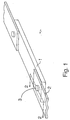
- FIGS. 1-6 illustrate a first embodiment of the method of the present invention for forming a bond between a metallic tab and a semiconductor element.
- a metallic power supply tab is bonded to a semiconductor element to provide an electrical heater.
- FIGS. 1 and 2 show a semiconductor element 1 in physical contact with metallic tab 2, which are to be mechanically and electrically bonded according to the first embodiment of the method of the present invention.
- semiconductor element 1 is silicon doped with n- or p-type impurities to achieve a desired electrical resistivity to form a semiconductor heater element.
- Element 1 may be of any size suitable for its intended application.
- semiconductor element 1 can be of a miniature size (e.g., about 0.25 mm (10 mils) to about 0.38 mm (15 mils) thick), about 1.5 mm wide and about 14 mm to about 16 mm long).
- Metallic tab 2 is adapted to provide an ohmic contact to silicon element 1 while allowing for the convenient attachment of a power lead (not shown) to provide electrical current flow through semiconductor element 1.
- metallic tab 2 may have any alloy or pure metal composition that quickly and easily reacts with molten silicon to form a metal silicide, as will be discussed below.
- silicide-formers copper, nickel and iron, copper is preferred for its relatively quick silicide formation reaction, low silicide formation temperature (about 850°C), abundant availability and low cost.
- metallic tab 2 preferably comprises a copper alloy having a high proportion of copper, alloyed with a transition metal element that has good oxidation resistance (e.g., a 80Cu-20Ni or Cu-Cr-Ni alloy).
- the metallic tab may comprise a copper-phosphor bronze alloy (e.g., comprising about 79.7% copper, 10% tin, 9.5% antimony and 0.8% phosphorous).
- metallic tab 2 can include as alloying elements one or more oxidation resistant metals such as nickel, chromium, titanium or molybdenum.
- Metallic tab 2 preferably comprises a metallic foil, for example less than about 0.25 mm (10 mils) thick, more preferably about 0.08 mm (3 mils) to about 0.20 mm (8 mils) thick and most preferably about 0.15 mm (6 mils) to about 0.20 mm (8 mils) thick.
- tab 2 is preferably about the width of the semiconductor element in the present embodiment but may have other dimensions as appropriate for its intended application.
- metallic tab 2 includes via hole 3 passing through its thickness.
- Via hole 3 is generally preformed by any known process such as drilling, punching, mask etching, etc.
- via hole 3 may be formed by a laser beam in a separate operation or in the same operation as the application of laser beam L for melting silicon as described below with reference to FIG. 3.
- Via hole 3 has a diameter of about 0.5 mm (20 mils) in the preferred embodiment, but can have any diameter that will allow the hole to be substantially filled by metal silicide upon melting of the silicon and reaction with the metal as will be discussed below.
- the two parts are suitably positioned and held relative to each other, to correspond approximately to the final intended arrangement of the parts.
- Tab 2 is positioned so that via hole 3 is at the intended bond location and so that contact surface 20 of tab 2 sufficiently overlaps contact surface 10 of element 1.
- tab 2 overlaps or contacts element 1 on contact surfaces 10 and 20 having a contact area of from about 1 mm2 to about 5 mm2.
- metallic tab 2 is pressed against semiconductor element 1 so that the two parts are in intimate surface contact on the contact surfaces 10 and 20.
- the contact surface 10, the contact surface 20 and/or the inner surface of the via hole 3 can be cleaned, for example by wet chemical etching or mechanical cleaning and polishing, to remove any significant oxides or contaminants before tab 2 and semiconductor element 1 are pressed together. It has generally been found that pressing a metallic foil tab against a semiconductor element causes the foil contact surface 20 to conform and partially adhere to semiconductor contact surface 10, whereby air gaps between the parts are substantially reduced.
- an optional preheating step may be carried out. It has been found that preheating the semiconductor-metal system improves the final bond by reducing stresses that occur during the rapid solidification of molten material after the laser heating step described below.
- the parts may be preheated by conduction from a conventional heating element placed in contact with at least one of the parts, while flowing argon or nitrogen or another inert gas over the interface area to reduce oxidation during the preheating step.
- the parts are preferably preheated to at least about 300°C and most preferably up to about 600°C.
- Heating energy L is preferably a laser beam, most preferably a pulsed laser beam from a neodymium:yttrium-aluminum-garnet (Nd:YAG) laser.
- Nd:YAG neodymium:yttrium-aluminum-garnet
- a Nd:YAG laser beam having a pulse duration of about 5 msec, a spot diameter of about 0.013 mm (0.5 mil) and a dwell time adjusted to deliver about 8 joules of energy.
- a laser beam is preferred as a heating energy source because it can rapidly provide a high energy density to a localized heating zone.
- the intensity and localization of the heating achieves low internal stress and distortion of the parts, fast cooling of the molten material and uniform solidification of a metal silicide formed from the intermixed metal and semiconductor product.
- any other controllable and localizable heating energy source such as a microflame, may be used. In such cases it is preferable to carry out the heating under an inert gas atmosphere to avoid oxidation during longer heating times.
- Any controllable gas or solid state laser may be used according to the invention.
- the selected laser may operate in a controlled continuous-wave manner or in a pulsed manner.
- a pulsed Nd:YAG laser is preferable to a continuous-wave CO2 laser, for example, because it can be easier to control the YAG laser pulses to apply a controlled amount of energy to the thin materials to be bonded.
- it can be easier to focus a YAG laser than a CO2 laser on the small geometries involved.
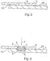
- Interface 4 may have a bulb or inverted mushroom shape, because of the penetration of the laser beam L into the silicon and because of the conduction of heat into the silicon material.
- the laser beam L possibly vaporizes some silicon material at the surface of semiconductor element 1 before melting silicon within the bulb-shaped penetration area.
- the molten silicon 5 rises into via hole 3, possibly by capillary, boiling or other action. Because the molten silicon 5 is at a temperature above about 1400°C (i.e. its approximate melting temperature), which is substantially higher than the melting temperature of copper alloy 2 (for example, about 1200°C), the copper alloy in area 6 around the perimeter wall of via hole 3 begins to melt. Molten silicon 5 intermixes and reacts with the molten copper alloy 6, to form a metal silicide, substantially copper silicide. The intermixed silicon-metal product rises in via hole 3 and, because of surface tension, forms a rough, substantially concave surface 7 below the outer surface of metallic tab 2.
- Laser beam L can be applied as described above to melt silicon 5 in a single pulse or in multiple pulses.
- Laser beam L can be directed to impinge upon the silicon while staying clear of the walls of via hole 3 or to partially impinge upon the copper alloy around via hole 3.
- Directing laser beam L partially at the copper alloy assures that copper alloy in area 6 will melt readily and react with molten silicon. Good control of the process and good results have been achieved by directing three or four sequential pulses of laser beam L at three or four locations around the perimeter of via hole 3.
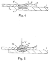
- Slug 5' is believed to comprise a complex, intermixed, reacted product that may include one or more of the following components: amorphous or semi-crystalline silicon (formed during rapid cooling after laser beam L is switched off), crystalline or semi-crystalline metal, metal silicide, and other components.
- the bottom of slug 5' is defined by bulb-shaped interface 4' between slug 5' and the silicon material of element 1. Along this interface, some metal atoms, e.g., copper and nickel atoms that intermixed into slug 5' while it was in a molten state (5), have diffused and intermixed into the silicon surrounding slug 5'.
- the top of slug 5' in this embodiment has a substantially concave surface 7' within via hole 3 and preferably below the upper surface of metallic tab 2.
- metal silicide of slug 5' is exposed to the environment at concave surface 7'.
- Metal silicides such as copper silicide in the present embodiment, are typically subject to rapid oxidation if exposed to atmospheric oxygen and moisture, even at room temperature. Oxidation and degradation are accelerated at the elevated temperatures occurring in smoking article heaters such as those described in above-incorporated U.S. patent application Serial No. 07/943,505.
- Oxidation of the copper silicide can cause two deleterious effects on the bond between metallic tab 2 and semiconductor element 1. First, oxidation may increase the electrical resistance of the copper silicide and impair the ohmic contact achieved by the bond. Second, oxidation may embrittle the silicide-copper interface and thereby may impair the mechanical strength of the bond. As described below and in accordance with the present invention, concave surface 7' can be sealed or otherwise protected from oxidation if desired.
- optional protection against oxidation of the copper silicide can be provided by applying a protective layer or cap to the upper surface 7' of slug 5'.
- additional or secondary oxidation resistance may be provided by using a metal alloy in tab 2 that includes oxidation resistant metals as described above. These oxidation resistant alloy metals of tab 2 also may form metal silicides within slug 5' that are more resistant to oxidation than is copper silicide, for example.
- FIG. 5 shows an oxidation resistant material 9 applied on surface 7' of slug 5'.
- Material g is preferably an oxidation resistant metal, such as nickel, that can be melted to form a cap over surface 7' and that bonds with surface 7'.
- the oxidation resistant material 9 can be applied in the form of a powder, bead, paste, piece of wire or some other form.
- a heat energy beam L' is applied to melt material 9.
- the energy beam L' may be a laser beam controlled as desired to an appropriate beam energy, spot diameter, pulse duration, dwell time, etc.
- laser beam L' may be produced by the same laser device that produces laser beam L described above, by simply readjusting beam parameters as desired.
- nickel material 9, for example
- copper silicide has a melting temperature of about 850°C
- the nickel material 9 intermixes with the copper and silicon near surface 7', forms a protective nickel alloy coating and becomes well bonded to surface 7' of slug 5'. If desired, material 9 may be applied before slug 5' has cooled, to facilitate bonding of material 9 to surface 7'.
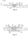
- the amount of material 9 is sufficient to at least cover surface 7' and partially fill the remaining space of via hole 3 upon melting. If desired, material 9 can fill via hole 3 at least flush with the surface of metallic tab 2. As shown in FIG. 6, after laser beam L' has been switched off and material 9 has melted and resolidified to form protective cap 9', the surface of cap 9' can have a slightly rounded head protruding above the surface of metallic tab 2. Alternatively, cap 9' can have a nearly flush surface like cap 9'' shown in FIG. 8 and described below. Protective cap 9' seals surface 7' from the environment and reduces oxidation of the metal silicides of slug 5' because it is relatively oxidation resistant, especially after forming a layer of nickel oxide or other oxide that resists further oxidation.
- FIGS. 1-6 illustrate a first embodiment of the method of the present invention for forming a bond between a metallic tab and a semiconductor element to provide an electrical heater.
- the bond can include a protective layer or cap for protection against oxidation.
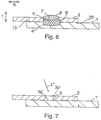
- FIGS. 7 and 8 illustrate a further embodiment of the method of the present invention.
- via hole 3' in metallic tab 2' may have a slightly conical shape, with sloped sidewalls 3a'.
- Metallic tab 2' and semiconductor element 1' are arranged substantially as described above with reference to FIGS. 1 and 2.
- laser beam L" is applied substantially as described above with reference to FIG. 3
- laser beam L'' impinges on lower portions 3b' of sloped sidewalls 3a'.
- Lower portions 3b', comprising the metallic material of tab 2' are melted by laser beam L", which then also melts silicon material of element 1', substantially as shown and described with reference to FIG. 3.
- laser beam L" may be applied at an angle as shown in FIG. 7, rather than substantially perpendicularly to the surface of semiconductor element 1 as shown for laser beam L in FIG. 3. Such an angled application of laser beam L" may aid in forming a bulb-shaped silicon melt-zone defined by interface 4" in FIG. 8.
- the laser beam shown and described here with reference to FIG. 7 may be directed perpendicularly like laser beam L shown in FIG. 3.
- Slug 5" is bounded essentially by a bulb-shaped interface 4" between slug 5" and the semiconductor element 1', a top concave surface 7" within via hole 3' and conical-shaped sidewalls defined by sloped walls 3a' of via hole 3'.
- an oxidation resistant protective cap 9" has been formed in a manner similar to cap 9' described above with reference to FIGS. 5 and 6.
- Protective cap 9" shown here is nearly flush with the surface of metallic tab 2', with only a slightly rounded top surface protruding from metallic tab 2'.
- FIGS. 7 and 8 illustrate a second embodiment of the method of the present invention for forming a bond between a metallic tab and a semiconductor element, especially to provide an electrical heater.
- FIGS. 1-8 provides a good mechanical bond and an ohmic, low resistance contact between a semiconductor element and a metallic tab, to which a power lead may then be conveniently attached.
- a path of low electrical resistance is provided from metallic tab 2, through the transition area interface 6' between metallic tab 2 and slug 5', through slug 5', through interface 4' between slug 5' and semiconductor element 1, and finally into semiconductor element 1.
- Another path of electrical conduction is through contact surfaces 10 and 20 of element 1 and tab 2, respectively.
- the low resistance, ohmic contact achieved according to the invention has been found to be quite robust and stable. Tests have shown that a heater comprising a semiconductor element and a metallic tab bonded according to the invention can be subjected to over 1000 heating/ cooling cycles (achieving surface temperatures in excess of 800°C) with little degradation of the electrical characteristics of the ohmic contact.
- the bond formed according to the method of the invention is mechanically strong in direction S (FIGS. 6 and 8), i.e., when shear is applied to slug 5' or 5", e.g., when element 1, 1" is pulled to the right and tab 2, 2" is pulled to the left. It should be understood that a similar shear may arise in the direction perpendicular to the plane of the drawings of FIGS. 6 and 8. Mechanical pull tests have shown that the silicon semiconductor element breaks before the welded bond according to the invention would break.
- interface 4', 4" between the semiconductor and metal silicide slug 5', 5" may be relatively brittle.
- the welded bond is generally not as strong in direction T in comparison to direction S (FIGS. 6 and 8), i.e., when tension is applied to slug 5', 5".
- the slug 5', 5" may tend to pull out of the element 1, 1' along the interface 4', 4" or possibly along the interface 6', 3a'.
- the strength of the bond in direction T is improved in the embodiment of FIG. 8 compared to that of FIG.
- the method of the present invention provides a bond between a semiconductor element and a metallic tab that has low, ohmic electrical resistance, high mechanical strength and little degradation of these properties after repeated thermal cycling. It is further advantageous that the method of the invention can be carried out in relatively few steps and in a short total time, for example, within a few seconds or less. It has been observed that the above described application of laser beam heating, melting of silicon material, and intermixing, reaction and solidification of a metal silicide product can be carried out within about 20 milliseconds to about 50 milliseconds.
- FIG. 9 shows the arrangement of components of FIG. 6 with the addition of mechanical clip 10. It should be understood that the components of FIG. 8 can also be used with a clip as shown in FIG. 9.
- Clip 10 as shown in FIG. 9 includes two upper shanks 10a and 10b, which press on the top of tab 2, and one lower shank 10c, which presses on the bottom of element 1.
- the upper shanks 10a and 10b are spaced apart and positioned to the respective sides of the protective cap 9' of the welded bond. If viewed from the side, the upper shanks 10a, 10b together with lower shank 10c, joined by a back spine (not visible in FIG. 9) form an essentially C-shaped clip.
- Shanks 10a, 10b may be received in grooves 11a, 11b respectively, in the top of metallic tab 2.
- Shank 10c may be received in groove 11c in the bottom of element 1.
- Grooves 11a and 11b can be pre-formed in metallic tab 2 and groove 11c can be pre-formed in the semiconductor element 1 by various known processes.
- Shanks 10a and 10b pressing toward shank 10c provide a resistance to mechanical tension in direction T shown in FIGS. 6 and 8.
- Shanks 10a, 10b and 10c fitting into respective grooves 11a, 11b and 11c provide a resistance to mechanical shear in direction S shown in FIGS. 6 and 8.
- the mechanical clip provides additional mechanical strength beyond that achieved in the embodiments described with reference to FIGS. 6 and 8.
- Preferred semiconductor heaters according to the invention can have a resistivity of from 1 ⁇ cm to 10 ⁇ cm and may be as low as 10 ⁇ 3 ⁇ cm or lower.
- the resistance of heaters according to the invention is preferably from 0.5 ⁇ to 3 ⁇ .
- Heaters according to the invention find particular application in heaters for smoking articles of the type shown in Figures 10 and 11.
- a heater unit 110 which is to be employed in a smoking article, includes heater unit base 105 and a plurality of heaters 111-118, which are preferably made from the doped silicon semiconductor material discussed above.
- Each heater 111-118 preferably is substantially rectangular and has two ends, labelled 111A-118A and 111B-118B, respectively, for providing ohmic electrical contacts to the heater.
- Base 105 is preferably fabricated out of elecrically insulating and thermally stable material.
- Heater ends 111A-118A are attached to base 105 at collar 104 on the circumference of base 105. Heater ends 111A-118A provide the common connection for heater unit 110 and should therefore all be electrically connected together at a point adjacent collar 104. Preferably, collar 104 is electrically conducting under the regions where heater ends 111A-118A contact collar 104. In the alternative, if collar 104 is made from electrically insulating material, then heater ends 111A-118A should be electrically connected together by some other means adjacent collar 104.
- Terminals 121-128 are provided for individually contacting heater ends 111B-118B. Individual wire connections can be provided from each heater end 111B-118B to its corresponding terminal 121-128, respectively. These individual wires (not shown) can run down center region 106 of unit 110, at the periphery 107 of unit 110, adjacent any of heaters 111-118 or by any other means which allows a connection to heater ends 111B-118B. Terminals 121-128, although shown as cylindrical in FIGS. 10 and 11, can be any shape, corresponding to the shape of mating sockets on a source of electrical energy (e.g., batteries, which can be rechargeable if desired, or other portable energy sources), to allow heaters 111-118 to be individually electrically activated.
- a source of electrical energy e.g., batteries, which can be rechargeable if desired, or other portable energy sources
- tobacco flavor material is positioned adjacent one or both substantially flat sides of each heater 111-118 (e.g., sides 113C and 113D of heater 113).
- heater unit 110 is permanent, and a disposable tobacco flavor material unit is inserted into a permanent heater unit 110. Accordingly, tobacco flavor material can be inserted into center region 106 or can be placed adjacent periphery 107.
- base 105 may include one or more air passageways (not shown) to allow air to be drawn from the region adjacent terminals 121-128, through base 105, to center region 106 of unit 110.
Landscapes
- Engineering & Computer Science (AREA)
- Mechanical Engineering (AREA)
- Physics & Mathematics (AREA)
- Optics & Photonics (AREA)
- Plasma & Fusion (AREA)
- Computer Hardware Design (AREA)
- Microelectronics & Electronic Packaging (AREA)
- Power Engineering (AREA)
- Manufacturing & Machinery (AREA)
- General Physics & Mathematics (AREA)
- Condensed Matter Physics & Semiconductors (AREA)
- Resistance Heating (AREA)
- Bipolar Transistors (AREA)
- Internal Circuitry In Semiconductor Integrated Circuit Devices (AREA)
- Wire Bonding (AREA)
- Electronic Switches (AREA)
- Investigating Or Analyzing Materials By The Use Of Fluid Adsorption Or Reactions (AREA)
- Apparatuses And Processes For Manufacturing Resistors (AREA)
- Die Bonding (AREA)
- Pressure Welding/Diffusion-Bonding (AREA)
Applications Claiming Priority (2)
| Application Number | Priority Date | Filing Date | Title |
|---|---|---|---|
| US08/073,539 US5498850A (en) | 1992-09-11 | 1993-06-08 | Semiconductor electrical heater and method for making same |
| US73539 | 1993-06-08 |
Publications (2)
| Publication Number | Publication Date |
|---|---|
| EP0628376A1 true EP0628376A1 (fr) | 1994-12-14 |
| EP0628376B1 EP0628376B1 (fr) | 1999-12-15 |
Family
ID=22114304
Family Applications (1)
| Application Number | Title | Priority Date | Filing Date |
|---|---|---|---|
| EP94304127A Expired - Lifetime EP0628376B1 (fr) | 1993-06-08 | 1994-06-08 | Elément chauffant électrique, ainsi que méthode de fabrication |
Country Status (12)
| Country | Link |
|---|---|
| US (2) | US5498850A (fr) |
| EP (1) | EP0628376B1 (fr) |
| JP (1) | JP3418248B2 (fr) |
| KR (1) | KR100363780B1 (fr) |
| AT (1) | ATE187667T1 (fr) |
| DE (1) | DE69422087T2 (fr) |
| DK (1) | DK0628376T3 (fr) |
| ES (1) | ES2142378T3 (fr) |
| GR (1) | GR3032886T3 (fr) |
| MY (1) | MY111221A (fr) |
| PT (1) | PT628376E (fr) |
| TW (1) | TW272312B (fr) |
Cited By (8)
| Publication number | Priority date | Publication date | Assignee | Title |
|---|---|---|---|---|
| US5659656A (en) * | 1992-09-11 | 1997-08-19 | Philip Morris Incorporated | Semiconductor electrical heater and method for making same |
| WO2009132684A1 (fr) * | 2008-04-30 | 2009-11-05 | Esk Ceramics Gmbh & Co. Kg | Procédé de fixation d'un élément de liaison sur une pièce, et composant comprenant une pièce avec un élément de liaison fixé sur celle-ci |
| CN102753048A (zh) * | 2009-12-23 | 2012-10-24 | 菲利普莫里斯生产公司 | 用于电加热的生成浮质的系统的细长的加热器 |
| WO2014037794A3 (fr) * | 2012-09-04 | 2014-05-01 | R. J. Reynolds Tobacco Company | Article électronique pour fumeur comprenant un ou plusieurs microfilaments chauffants |
| DE102016003302A1 (de) * | 2016-03-15 | 2017-09-21 | Hochschule Mittweida (Fh) | Verfahren zum Verbinden wenigstens bereichsweise übereinander angeordneter Werkstücke mittels Laserstrahlung und Verbindung |
| WO2017182249A1 (fr) * | 2016-04-22 | 2017-10-26 | Philip Morris Products S.A. | Dispositif de génération d'aérosol comprenant des dispositifs de chauffage à semi-conducteurs |
| US10645972B2 (en) | 2016-04-22 | 2020-05-12 | Altria Client Services Llc | Aerosol-generating device comprising semiconductor heaters |
| US11871484B2 (en) | 2013-03-15 | 2024-01-09 | Rai Strategic Holdings, Inc. | Aerosol delivery device |
Families Citing this family (220)
| Publication number | Priority date | Publication date | Assignee | Title |
|---|---|---|---|---|
| US5676865A (en) * | 1995-08-25 | 1997-10-14 | Thomas & Betts Corporation | Method of and apparatus for providing welded joints |
| DE10036901C2 (de) * | 2000-07-28 | 2002-08-01 | Siemens Ag | Verfahren und Vorrichtung zur Erzeugung einer Laserschweißverbindung |
| US6960738B2 (en) * | 2001-05-29 | 2005-11-01 | Koninklijke Philips Electronics N.V. | Metal-ceramic bond |
| US7521651B2 (en) * | 2003-09-12 | 2009-04-21 | Orbotech Ltd | Multiple beam micro-machining system and method |
| DE102004027806A1 (de) * | 2004-06-08 | 2006-01-05 | Patent-Treuhand-Gesellschaft für elektrische Glühlampen mbH | Verfahren zum Verschweißen einer Metallfolie mit einem zylindrischen Metallstift |
| US8089030B2 (en) * | 2005-01-18 | 2012-01-03 | Marvel Concepts, Llc | Bucky warmer with holder |
| JP2007265962A (ja) * | 2006-02-28 | 2007-10-11 | Hitachi Ltd | レーザ溶接方法,コントロールユニットの製造方法、及び車両用コントロールユニット |
| JP2008073711A (ja) * | 2006-09-20 | 2008-04-03 | Disco Abrasive Syst Ltd | ビアホールの加工方法 |
| US7726320B2 (en) | 2006-10-18 | 2010-06-01 | R. J. Reynolds Tobacco Company | Tobacco-containing smoking article |
| AU2011245104B8 (en) | 2010-04-30 | 2013-07-11 | Fontem Holdings 4 B.V. | Electronic smoking device |
| US11344683B2 (en) | 2010-05-15 | 2022-05-31 | Rai Strategic Holdings, Inc. | Vaporizer related systems, methods, and apparatus |
| US9999250B2 (en) | 2010-05-15 | 2018-06-19 | Rai Strategic Holdings, Inc. | Vaporizer related systems, methods, and apparatus |
| US9259035B2 (en) | 2010-05-15 | 2016-02-16 | R. J. Reynolds Tobacco Company | Solderless personal vaporizing inhaler |
| US9095175B2 (en) | 2010-05-15 | 2015-08-04 | R. J. Reynolds Tobacco Company | Data logging personal vaporizing inhaler |
| US9861772B2 (en) | 2010-05-15 | 2018-01-09 | Rai Strategic Holdings, Inc. | Personal vaporizing inhaler cartridge |
| US10136672B2 (en) | 2010-05-15 | 2018-11-27 | Rai Strategic Holdings, Inc. | Solderless directly written heating elements |
| US8757147B2 (en) | 2010-05-15 | 2014-06-24 | Minusa Holdings Llc | Personal vaporizing inhaler with internal light source |
| US10159278B2 (en) | 2010-05-15 | 2018-12-25 | Rai Strategic Holdings, Inc. | Assembly directed airflow |
| US9743691B2 (en) | 2010-05-15 | 2017-08-29 | Rai Strategic Holdings, Inc. | Vaporizer configuration, control, and reporting |
| AT510837B1 (de) | 2011-07-27 | 2012-07-15 | Helmut Dr Buchberger | Inhalatorkomponente |
| ES2543312T3 (es) | 2011-02-11 | 2015-08-18 | Batmark Limited | Componente para inhalador |
| US9078473B2 (en) | 2011-08-09 | 2015-07-14 | R.J. Reynolds Tobacco Company | Smoking articles and use thereof for yielding inhalation materials |
| KR102196913B1 (ko) | 2011-09-06 | 2020-12-30 | 니코벤처스 트레이딩 리미티드 | 가열식 흡연가능 재료 |
| US20130255702A1 (en) | 2012-03-28 | 2013-10-03 | R.J. Reynolds Tobacco Company | Smoking article incorporating a conductive substrate |
| US10004259B2 (en) | 2012-06-28 | 2018-06-26 | Rai Strategic Holdings, Inc. | Reservoir and heater system for controllable delivery of multiple aerosolizable materials in an electronic smoking article |
| US8910639B2 (en) | 2012-09-05 | 2014-12-16 | R. J. Reynolds Tobacco Company | Single-use connector and cartridge for a smoking article and related method |
| GB201217067D0 (en) | 2012-09-25 | 2012-11-07 | British American Tobacco Co | Heating smokable material |
| US9854841B2 (en) | 2012-10-08 | 2018-01-02 | Rai Strategic Holdings, Inc. | Electronic smoking article and associated method |
| US10117460B2 (en) | 2012-10-08 | 2018-11-06 | Rai Strategic Holdings, Inc. | Electronic smoking article and associated method |
| US10034988B2 (en) | 2012-11-28 | 2018-07-31 | Fontem Holdings I B.V. | Methods and devices for compound delivery |
| US9210738B2 (en) | 2012-12-07 | 2015-12-08 | R.J. Reynolds Tobacco Company | Apparatus and method for winding a substantially continuous heating element about a substantially continuous wick |
| US8910640B2 (en) | 2013-01-30 | 2014-12-16 | R.J. Reynolds Tobacco Company | Wick suitable for use in an electronic smoking article |
| US10031183B2 (en) | 2013-03-07 | 2018-07-24 | Rai Strategic Holdings, Inc. | Spent cartridge detection method and system for an electronic smoking article |
| US20140261486A1 (en) | 2013-03-12 | 2014-09-18 | R.J. Reynolds Tobacco Company | Electronic smoking article having a vapor-enhancing apparatus and associated method |
| US9277770B2 (en) | 2013-03-14 | 2016-03-08 | R. J. Reynolds Tobacco Company | Atomizer for an aerosol delivery device formed from a continuously extending wire and related input, cartridge, and method |
| US9918495B2 (en) | 2014-02-28 | 2018-03-20 | Rai Strategic Holdings, Inc. | Atomizer for an aerosol delivery device and related input, aerosol production assembly, cartridge, and method |
| US20140261487A1 (en) | 2013-03-14 | 2014-09-18 | R. J. Reynolds Tobacco Company | Electronic smoking article with improved storage and transport of aerosol precursor compositions |
| PL2967154T3 (pl) | 2013-03-14 | 2019-04-30 | Reynolds Tobacco Co R | Rozpylacz dla urządzenia dostarczającego aerozol i powiązane wkładka, zespół do wytwarzania aerozolu, wkład i sposób |
| US9609893B2 (en) | 2013-03-15 | 2017-04-04 | Rai Strategic Holdings, Inc. | Cartridge and control body of an aerosol delivery device including anti-rotation mechanism and related method |
| US9491974B2 (en) | 2013-03-15 | 2016-11-15 | Rai Strategic Holdings, Inc. | Heating elements formed from a sheet of a material and inputs and methods for the production of atomizers |
| CN105163612B (zh) | 2013-03-15 | 2019-08-06 | R·J·雷诺兹烟草公司 | 由材料的薄片形成加热元件、用于产生雾化器的输入端和方法,用于气雾剂递送装置的套筒以及用于组装用于吸烟物品的套筒的方法 |
| US9423152B2 (en) | 2013-03-15 | 2016-08-23 | R. J. Reynolds Tobacco Company | Heating control arrangement for an electronic smoking article and associated system and method |
| GB201311620D0 (en) | 2013-06-28 | 2013-08-14 | British American Tobacco Co | Devices Comprising a Heat Source Material and Activation Chambers for the Same |
| US11229239B2 (en) | 2013-07-19 | 2022-01-25 | Rai Strategic Holdings, Inc. | Electronic smoking article with haptic feedback |
| US10172387B2 (en) | 2013-08-28 | 2019-01-08 | Rai Strategic Holdings, Inc. | Carbon conductive substrate for electronic smoking article |
| WO2015042412A1 (fr) | 2013-09-20 | 2015-03-26 | E-Nicotine Technology. Inc. | Dispositifs et procédés de modification de dispositifs de distribution |
| US9806549B2 (en) | 2013-10-04 | 2017-10-31 | Rai Strategic Holdings, Inc. | Accessory for an aerosol delivery device and related method and computer program product |
| US10292424B2 (en) | 2013-10-31 | 2019-05-21 | Rai Strategic Holdings, Inc. | Aerosol delivery device including a pressure-based aerosol delivery mechanism |
| US20150128969A1 (en) | 2013-11-11 | 2015-05-14 | R.J. Reynolds Tobacco Company | Mouthpiece for smoking article |
| US20150128968A1 (en) | 2013-11-11 | 2015-05-14 | R.J. Reynolds Tobacco Company | Mouthpiece for smoking article |
| US9839237B2 (en) | 2013-11-22 | 2017-12-12 | Rai Strategic Holdings, Inc. | Reservoir housing for an electronic smoking article |
| US20150181935A1 (en) * | 2013-12-27 | 2015-07-02 | British American Tobacco (Investments) Limited | Apparatus for Heating Smokeable Material |
| US9974334B2 (en) | 2014-01-17 | 2018-05-22 | Rai Strategic Holdings, Inc. | Electronic smoking article with improved storage of aerosol precursor compositions |
| CN106455705A (zh) | 2014-01-22 | 2017-02-22 | 方特慕控股第私人有限公司 | 用于吸烟欲望救济的方法和装置 |
| US10575558B2 (en) | 2014-02-03 | 2020-03-03 | Rai Strategic Holdings, Inc. | Aerosol delivery device comprising multiple outer bodies and related assembly method |
| US9451791B2 (en) | 2014-02-05 | 2016-09-27 | Rai Strategic Holdings, Inc. | Aerosol delivery device with an illuminated outer surface and related method |
| US20150224268A1 (en) | 2014-02-07 | 2015-08-13 | R.J. Reynolds Tobacco Company | Charging Accessory Device for an Aerosol Delivery Device and Related System, Method, Apparatus, and Computer Program Product for Providing Interactive Services for Aerosol Delivery Devices |
| US9833019B2 (en) | 2014-02-13 | 2017-12-05 | Rai Strategic Holdings, Inc. | Method for assembling a cartridge for a smoking article |
| US9839238B2 (en) | 2014-02-28 | 2017-12-12 | Rai Strategic Holdings, Inc. | Control body for an electronic smoking article |
| US9597466B2 (en) | 2014-03-12 | 2017-03-21 | R. J. Reynolds Tobacco Company | Aerosol delivery system and related method, apparatus, and computer program product for providing control information to an aerosol delivery device via a cartridge |
| US11696604B2 (en) | 2014-03-13 | 2023-07-11 | Rai Strategic Holdings, Inc. | Aerosol delivery device and related method and computer program product for controlling an aerosol delivery device based on input characteristics |
| US9877510B2 (en) | 2014-04-04 | 2018-01-30 | Rai Strategic Holdings, Inc. | Sensor for an aerosol delivery device |
| GB201407426D0 (en) * | 2014-04-28 | 2014-06-11 | Batmark Ltd | Aerosol forming component |
| US20150313282A1 (en) | 2014-05-01 | 2015-11-05 | R.J. Reynolds Tobacco Company | Electronic smoking article |
| US9924741B2 (en) | 2014-05-05 | 2018-03-27 | Rai Strategic Holdings, Inc. | Method of preparing an aerosol delivery device |
| US20150335070A1 (en) | 2014-05-20 | 2015-11-26 | R.J. Reynolds Tobacco Company | Electrically-powered aerosol delivery system |
| US9955726B2 (en) | 2014-05-23 | 2018-05-01 | Rai Strategic Holdings, Inc. | Sealed cartridge for an aerosol delivery device and related assembly method |
| US10099315B2 (en) * | 2014-06-27 | 2018-10-16 | Jabil Inc. | System, apparatus and method for hybrid function micro welding |
| GB201500582D0 (en) | 2015-01-14 | 2015-02-25 | British American Tobacco Co | Apparatus for heating or cooling a material contained therein |
| US10888119B2 (en) | 2014-07-10 | 2021-01-12 | Rai Strategic Holdings, Inc. | System and related methods, apparatuses, and computer program products for controlling operation of a device based on a read request |
| US10058123B2 (en) | 2014-07-11 | 2018-08-28 | R. J. Reynolds Tobacco Company | Heater for an aerosol delivery device and methods of formation thereof |
| US9609895B2 (en) | 2014-08-21 | 2017-04-04 | Rai Strategic Holdings, Inc. | System and related methods, apparatuses, and computer program products for testing components of an aerosol delivery device |
| US9913493B2 (en) | 2014-08-21 | 2018-03-13 | Rai Strategic Holdings, Inc. | Aerosol delivery device including a moveable cartridge and related assembly method |
| US10765144B2 (en) | 2014-08-21 | 2020-09-08 | Rai Strategic Holdings, Inc. | Aerosol delivery device including a moveable cartridge and related assembly method |
| DE102014116283B4 (de) * | 2014-11-07 | 2016-05-19 | Webasto SE | Verfahren zum Bearbeiten eines ersten Bauelements und eines zweiten Bauelements sowie Vorrichtung |
| US11051554B2 (en) | 2014-11-12 | 2021-07-06 | Rai Strategic Holdings, Inc. | MEMS-based sensor for an aerosol delivery device |
| US10500600B2 (en) | 2014-12-09 | 2019-12-10 | Rai Strategic Holdings, Inc. | Gesture recognition user interface for an aerosol delivery device |
| GB2533135B (en) | 2014-12-11 | 2020-11-11 | Nicoventures Holdings Ltd | Aerosol provision systems |
| US10321711B2 (en) | 2015-01-29 | 2019-06-18 | Rai Strategic Holdings, Inc. | Proximity detection for an aerosol delivery device |
| US10027016B2 (en) | 2015-03-04 | 2018-07-17 | Rai Strategic Holdings Inc. | Antenna for an aerosol delivery device |
| US9980516B2 (en) | 2015-03-09 | 2018-05-29 | Rai Strategic Holdings, Inc. | Aerosol delivery device including a wave guide and related method |
| US10172388B2 (en) | 2015-03-10 | 2019-01-08 | Rai Strategic Holdings, Inc. | Aerosol delivery device with microfluidic delivery component |
| US11000069B2 (en) | 2015-05-15 | 2021-05-11 | Rai Strategic Holdings, Inc. | Aerosol delivery device and methods of formation thereof |
| US10238145B2 (en) | 2015-05-19 | 2019-03-26 | Rai Strategic Holdings, Inc. | Assembly substation for assembling a cartridge for a smoking article |
| US10226073B2 (en) | 2015-06-09 | 2019-03-12 | Rai Strategic Holdings, Inc. | Electronic smoking article including a heating apparatus implementing a solid aerosol generating source, and associated apparatus and method |
| US10966460B2 (en) | 2015-07-17 | 2021-04-06 | Rai Strategic Holdings, Inc. | Load-based detection of an aerosol delivery device in an assembled arrangement |
| US11504489B2 (en) | 2015-07-17 | 2022-11-22 | Rai Strategic Holdings, Inc. | Contained liquid system for refilling aerosol delivery devices |
| US11134544B2 (en) | 2015-07-24 | 2021-09-28 | Rai Strategic Holdings, Inc. | Aerosol delivery device with radiant heating |
| US10206429B2 (en) | 2015-07-24 | 2019-02-19 | Rai Strategic Holdings, Inc. | Aerosol delivery device with radiant heating |
| US11033054B2 (en) | 2015-07-24 | 2021-06-15 | Rai Strategic Holdings, Inc. | Radio-frequency identification (RFID) authentication system for aerosol delivery devices |
| US10015987B2 (en) | 2015-07-24 | 2018-07-10 | Rai Strategic Holdings Inc. | Trigger-based wireless broadcasting for aerosol delivery devices |
| US20170055575A1 (en) | 2015-08-31 | 2017-03-02 | British American Tobacco (Investments) Limited | Material for use with apparatus for heating smokable material |
| US20170055584A1 (en) | 2015-08-31 | 2017-03-02 | British American Tobacco (Investments) Limited | Article for use with apparatus for heating smokable material |
| US11924930B2 (en) | 2015-08-31 | 2024-03-05 | Nicoventures Trading Limited | Article for use with apparatus for heating smokable material |
| US10034494B2 (en) | 2015-09-15 | 2018-07-31 | Rai Strategic Holdings, Inc. | Reservoir for aerosol delivery devices |
| US10058125B2 (en) | 2015-10-13 | 2018-08-28 | Rai Strategic Holdings, Inc. | Method for assembling an aerosol delivery device |
| US10918134B2 (en) | 2015-10-21 | 2021-02-16 | Rai Strategic Holdings, Inc. | Power supply for an aerosol delivery device |
| US10582726B2 (en) | 2015-10-21 | 2020-03-10 | Rai Strategic Holdings, Inc. | Induction charging for an aerosol delivery device |
| US20170112194A1 (en) | 2015-10-21 | 2017-04-27 | Rai Strategic Holdings, Inc. | Rechargeable lithium-ion capacitor for an aerosol delivery device |
| US20170119046A1 (en) | 2015-10-30 | 2017-05-04 | British American Tobacco (Investments) Limited | Apparatus for Heating Smokable Material |
| US20170119047A1 (en) | 2015-10-30 | 2017-05-04 | British American Tobacco (Investments) Limited | Article for Use with Apparatus for Heating Smokable Material |
| US10201187B2 (en) | 2015-11-02 | 2019-02-12 | Rai Strategic Holdings, Inc. | User interface for an aerosol delivery device |
| US10820630B2 (en) | 2015-11-06 | 2020-11-03 | Rai Strategic Holdings, Inc. | Aerosol delivery device including a wirelessly-heated atomizer and related method |
| DE102015119252B4 (de) | 2015-11-09 | 2024-02-01 | Webasto SE | Vorrichtung für ein Heizgerät für ein Fahrzeug |
| RU2733625C2 (ru) | 2015-11-24 | 2020-10-05 | Р. Дж. Рейнолдс Тобакко Компани | Система подачи аэрозоля с электрическим питанием |
| DE102015121064B3 (de) * | 2015-12-03 | 2017-02-16 | Bundesrepublik Deutschland, Vertreten Durch Den Bundesminister Für Wirtschaft Und Energie, Dieser Vertreten Durch Den Präsidenten Der Bundesanstalt Für Materialforschung Und -Prüfung (Bam) | Fügen durch Schmelzbadverdrängung |
| US10440992B2 (en) | 2015-12-07 | 2019-10-15 | Rai Strategic Holdings, Inc. | Motion sensing for an aerosol delivery device |
| US9955733B2 (en) | 2015-12-07 | 2018-05-01 | Rai Strategic Holdings, Inc. | Camera for an aerosol delivery device |
| US11291252B2 (en) | 2015-12-18 | 2022-04-05 | Rai Strategic Holdings, Inc. | Proximity sensing for an aerosol delivery device |
| US10092036B2 (en) | 2015-12-28 | 2018-10-09 | Rai Strategic Holdings, Inc. | Aerosol delivery device including a housing and a coupler |
| US10051891B2 (en) | 2016-01-05 | 2018-08-21 | Rai Strategic Holdings, Inc. | Capacitive sensing input device for an aerosol delivery device |
| US10194694B2 (en) | 2016-01-05 | 2019-02-05 | Rai Strategic Holdings, Inc. | Aerosol delivery device with improved fluid transport |
| US10258086B2 (en) | 2016-01-12 | 2019-04-16 | Rai Strategic Holdings, Inc. | Hall effect current sensor for an aerosol delivery device |
| US10104912B2 (en) | 2016-01-20 | 2018-10-23 | Rai Strategic Holdings, Inc. | Control for an induction-based aerosol delivery device |
| US10015989B2 (en) | 2016-01-27 | 2018-07-10 | Rai Strategic Holdings, Inc. | One-way valve for refilling an aerosol delivery device |
| US11412781B2 (en) | 2016-02-12 | 2022-08-16 | Rai Strategic Holdings, Inc. | Adapters for refilling an aerosol delivery device |
| US9936733B2 (en) | 2016-03-09 | 2018-04-10 | Rai Strategic Holdings, Inc. | Accessory configured to charge an aerosol delivery device and related method |
| US10334880B2 (en) | 2016-03-25 | 2019-07-02 | Rai Strategic Holdings, Inc. | Aerosol delivery device including connector comprising extension and receptacle |
| US11207478B2 (en) | 2016-03-25 | 2021-12-28 | Rai Strategic Holdings, Inc. | Aerosol production assembly including surface with micro-pattern |
| US10945462B2 (en) | 2016-04-12 | 2021-03-16 | Rai Strategic Holdings, Inc. | Detachable power source for an aerosol delivery device |
| US10333339B2 (en) | 2016-04-12 | 2019-06-25 | Rai Strategic Holdings, Inc. | Charger for an aerosol delivery device |
| US10028534B2 (en) | 2016-04-20 | 2018-07-24 | Rai Strategic Holdings, Inc. | Aerosol delivery device, and associated apparatus and method of formation thereof |
| WO2017187148A1 (fr) | 2016-04-27 | 2017-11-02 | Nicoventures Holdings Limited | Système de fourniture d'aérosol électronique et vaporisateur associé |
| US10405579B2 (en) | 2016-04-29 | 2019-09-10 | Rai Strategic Holdings, Inc. | Methods for assembling a cartridge for an aerosol delivery device, and associated systems and apparatuses |
| US10179690B2 (en) | 2016-05-26 | 2019-01-15 | Rai Strategic Holdings, Inc. | Aerosol precursor composition mixing system for an aerosol delivery device |
| US10959458B2 (en) | 2016-06-20 | 2021-03-30 | Rai Strategic Holdings, Inc. | Aerosol delivery device including an electrical generator assembly |
| US10085485B2 (en) | 2016-07-06 | 2018-10-02 | Rai Strategic Holdings, Inc. | Aerosol delivery device with a reservoir housing and a vaporizer assembly |
| US10405581B2 (en) | 2016-07-08 | 2019-09-10 | Rai Strategic Holdings, Inc. | Gas sensing for an aerosol delivery device |
| US10231485B2 (en) | 2016-07-08 | 2019-03-19 | Rai Strategic Holdings, Inc. | Radio frequency to direct current converter for an aerosol delivery device |
| US10463078B2 (en) | 2016-07-08 | 2019-11-05 | Rai Strategic Holdings, Inc. | Aerosol delivery device with condensing and non-condensing vaporization |
| US10617151B2 (en) | 2016-07-21 | 2020-04-14 | Rai Strategic Holdings, Inc. | Aerosol delivery device with a liquid transport element comprising a porous monolith and related method |
| US10602775B2 (en) | 2016-07-21 | 2020-03-31 | Rai Strategic Holdings, Inc. | Aerosol delivery device with a unitary reservoir and liquid transport element comprising a porous monolith and related method |
| US11019847B2 (en) | 2016-07-28 | 2021-06-01 | Rai Strategic Holdings, Inc. | Aerosol delivery devices including a selector and related methods |
| US10765146B2 (en) | 2016-08-08 | 2020-09-08 | Rai Strategic Holdings, Inc. | Boost converter for an aerosol delivery device |
| US11937647B2 (en) | 2016-09-09 | 2024-03-26 | Rai Strategic Holdings, Inc. | Fluidic control for an aerosol delivery device |
| US10080387B2 (en) | 2016-09-23 | 2018-09-25 | Rai Strategic Holdings, Inc. | Aerosol delivery device with replaceable wick and heater assembly |
| US10477896B2 (en) | 2016-10-12 | 2019-11-19 | Rai Strategic Holdings, Inc. | Photodetector for measuring aerosol precursor composition in an aerosol delivery device |
| US10256204B2 (en) | 2016-11-08 | 2019-04-09 | Globalfoundries Inc. | Separation of integrated circuit structure from adjacent chip |
| US10492530B2 (en) | 2016-11-15 | 2019-12-03 | Rai Strategic Holdings, Inc. | Two-wire authentication system for an aerosol delivery device |
| US10524508B2 (en) | 2016-11-15 | 2020-01-07 | Rai Strategic Holdings, Inc. | Induction-based aerosol delivery device |
| US9864947B1 (en) | 2016-11-15 | 2018-01-09 | Rai Strategic Holdings, Inc. | Near field communication for a tobacco-based article or package therefor |
| US11103012B2 (en) | 2016-11-17 | 2021-08-31 | Rai Strategic Holdings, Inc. | Satellite navigation for an aerosol delivery device |
| US10524509B2 (en) | 2016-11-18 | 2020-01-07 | Rai Strategic Holdings, Inc. | Pressure sensing for an aerosol delivery device |
| US10653183B2 (en) | 2016-11-18 | 2020-05-19 | Rai Strategic Holdings, Inc. | Power source for an aerosol delivery device |
| US10172392B2 (en) | 2016-11-18 | 2019-01-08 | Rai Strategic Holdings, Inc. | Humidity sensing for an aerosol delivery device |
| US10206431B2 (en) | 2016-11-18 | 2019-02-19 | Rai Strategic Holdings, Inc. | Charger for an aerosol delivery device |
| US10537137B2 (en) | 2016-11-22 | 2020-01-21 | Rai Strategic Holdings, Inc. | Rechargeable lithium-ion battery for an aerosol delivery device |
| US11013266B2 (en) | 2016-12-09 | 2021-05-25 | Rai Strategic Holdings, Inc. | Aerosol delivery device sensory system including an infrared sensor and related method |
| US10842188B2 (en) | 2016-12-14 | 2020-11-24 | Rai Strategic Holdings, Inc. | Smoking article for selective delivery of an aerosol precursor composition, a cartridge, and a related method |
| US10092039B2 (en) | 2016-12-14 | 2018-10-09 | Rai Strategic Holdings, Inc. | Smoking article for on-demand delivery of an increased quantity of an aerosol precursor composition, a cartridge, and a related method |
| US10366641B2 (en) | 2016-12-21 | 2019-07-30 | R.J. Reynolds Tobacco Company | Product display systems and related methods |
| US10080388B2 (en) | 2017-01-25 | 2018-09-25 | Rai Strategic Holdings, Inc. | Aerosol delivery device including a shape-memory alloy and a related method |
| US10517326B2 (en) | 2017-01-27 | 2019-12-31 | Rai Strategic Holdings, Inc. | Secondary battery for an aerosol delivery device |
| US10827783B2 (en) | 2017-02-27 | 2020-11-10 | Rai Strategic Holdings, Inc. | Digital compass for an aerosol delivery device |
| US10314340B2 (en) | 2017-04-21 | 2019-06-11 | Rai Strategic Holdings, Inc. | Refillable aerosol delivery device and related method |
| US11297876B2 (en) | 2017-05-17 | 2022-04-12 | Rai Strategic Holdings, Inc. | Aerosol delivery device |
| US10517330B2 (en) | 2017-05-23 | 2019-12-31 | RAI Stategic Holdings, Inc. | Heart rate monitor for an aerosol delivery device |
| US11589621B2 (en) | 2017-05-23 | 2023-02-28 | Rai Strategic Holdings, Inc. | Heart rate monitor for an aerosol delivery device |
| US10575562B2 (en) | 2017-06-30 | 2020-03-03 | Rai Strategic Holdings, Inc. | Smoking article for identifying an attribute of an aerosol-generating element for adaptive power output and an associated method |
| US10842197B2 (en) | 2017-07-12 | 2020-11-24 | Rai Strategic Holdings, Inc. | Detachable container for aerosol delivery having pierceable membrane |
| US10349674B2 (en) | 2017-07-17 | 2019-07-16 | Rai Strategic Holdings, Inc. | No-heat, no-burn smoking article |
| US11337456B2 (en) | 2017-07-17 | 2022-05-24 | Rai Strategic Holdings, Inc. | Video analytics camera system for an aerosol delivery device |
| US10791761B2 (en) | 2017-08-17 | 2020-10-06 | Rai Strategic Holdings, Inc. | Microtextured liquid transport element for aerosol delivery device |
| US10667554B2 (en) | 2017-09-18 | 2020-06-02 | Rai Strategic Holdings, Inc. | Smoking articles |
| US10505383B2 (en) | 2017-09-19 | 2019-12-10 | Rai Strategic Holdings, Inc. | Intelligent charger for an aerosol delivery device |
| US11039645B2 (en) | 2017-09-19 | 2021-06-22 | Rai Strategic Holdings, Inc. | Differential pressure sensor for an aerosol delivery device |
| US10660370B2 (en) | 2017-10-12 | 2020-05-26 | Rai Strategic Holdings, Inc. | Aerosol delivery device including a control body, an atomizer body, and a cartridge and related methods |
| US10517332B2 (en) | 2017-10-31 | 2019-12-31 | Rai Strategic Holdings, Inc. | Induction heated aerosol delivery device |
| US10806181B2 (en) | 2017-12-08 | 2020-10-20 | Rai Strategic Holdings, Inc. | Quasi-resonant flyback converter for an induction-based aerosol delivery device |
| US10786010B2 (en) | 2017-12-15 | 2020-09-29 | Rai Strategic Holdings, Inc. | Aerosol delivery device with multiple aerosol delivery pathways |
| US10555558B2 (en) | 2017-12-29 | 2020-02-11 | Rai Strategic Holdings, Inc. | Aerosol delivery device providing flavor control |
| DE102018200544A1 (de) * | 2018-01-15 | 2019-07-18 | Robert Bosch Gmbh | Verfahren und Vorrichtung zum Fügen von Folien für Batterien |
| US11019850B2 (en) | 2018-02-26 | 2021-06-01 | Rai Strategic Holdings, Inc. | Heat conducting substrate for electrically heated aerosol delivery device |
| DE102018105220A1 (de) | 2018-03-07 | 2019-09-12 | Hauni Maschinenbau Gmbh | Verfahren zur Fertigung eines elektrisch betreibbaren Heizkörpers für einen Inhalator |
| US10813385B2 (en) | 2018-03-09 | 2020-10-27 | Rai Strategic Holdings, Inc. | Buck regulator with operational amplifier feedback for an aerosol delivery device |
| US20190274354A1 (en) | 2018-03-09 | 2019-09-12 | Rai Strategic Holdings, Inc. | Electronically heated heat-not-burn smoking article |
| US11382356B2 (en) | 2018-03-20 | 2022-07-12 | Rai Strategic Holdings, Inc. | Aerosol delivery device with indexing movement |
| US11206864B2 (en) | 2018-03-26 | 2021-12-28 | Rai Strategic Holdings, Inc. | Aerosol delivery device providing flavor control |
| US10381322B1 (en) | 2018-04-23 | 2019-08-13 | Sandisk Technologies Llc | Three-dimensional memory device containing self-aligned interlocking bonded structure and method of making the same |
| US10959459B2 (en) | 2018-05-16 | 2021-03-30 | Rai Strategic Holdings, Inc. | Voltage regulator for an aerosol delivery device |
| US11094993B2 (en) | 2018-08-10 | 2021-08-17 | Rai Strategic Holdings, Inc. | Charge circuitry for an aerosol delivery device |
| US11265974B2 (en) | 2018-08-27 | 2022-03-01 | Rai Strategic Holdings, Inc. | Aerosol delivery device with integrated thermal conductor |
| US11103013B2 (en) | 2018-09-07 | 2021-08-31 | Fontem Holdings 1 B.V. | Pivotable charging case for electronic smoking device |
| US20200093181A1 (en) | 2018-09-20 | 2020-03-26 | Rai Strategic Holdings, Inc. | Flavorants |
| US11247005B2 (en) | 2018-09-26 | 2022-02-15 | Rai Strategic Holdings, Inc. | Aerosol delivery device with conductive inserts |
| US11614720B2 (en) | 2018-11-19 | 2023-03-28 | Rai Strategic Holdings, Inc. | Temperature control in an aerosol delivery device |
| US11592793B2 (en) | 2018-11-19 | 2023-02-28 | Rai Strategic Holdings, Inc. | Power control for an aerosol delivery device |
| US11753750B2 (en) | 2018-11-20 | 2023-09-12 | R.J. Reynolds Tobacco Company | Conductive aerosol generating composite substrate for aerosol source member |
| US20200154785A1 (en) | 2018-11-20 | 2020-05-21 | R.J. Reynolds Tobacco Company | Overwrap material containing aerosol former for aerosol source member |
| US11096419B2 (en) | 2019-01-29 | 2021-08-24 | Rai Strategic Holdings, Inc. | Air pressure sensor for an aerosol delivery device |
| US20200245696A1 (en) | 2019-02-06 | 2020-08-06 | Rai Strategic Holdings, Inc. | Buck-boost regulator circuit for an aerosol delivery device |
| US11456480B2 (en) | 2019-02-07 | 2022-09-27 | Rai Strategic Holdings, Inc. | Non-inverting amplifier circuit for an aerosol delivery device |
| US10879260B2 (en) | 2019-02-28 | 2020-12-29 | Sandisk Technologies Llc | Bonded assembly of a support die and plural memory dies containing laterally shifted vertical interconnections and methods for making the same |
| US20200278707A1 (en) | 2019-03-01 | 2020-09-03 | Rai Strategic Holdings, Inc. | Temperature control circuitry for an aerosol delivery device |
| US11324249B2 (en) | 2019-03-06 | 2022-05-10 | R.J. Reynolds Tobacco Company | Aerosol delivery device with nanocellulose substrate |
| US11676438B2 (en) | 2019-04-02 | 2023-06-13 | Rai Strategic Holdings, Inc. | Authentication and age verification for an aerosol delivery device |
| US11783395B2 (en) | 2019-04-24 | 2023-10-10 | Rai Strategic Holdings, Inc. | Decentralized identity storage for tobacco products |
| US11690405B2 (en) | 2019-04-25 | 2023-07-04 | Rai Strategic Holdings, Inc. | Artificial intelligence in an aerosol delivery device |
| US20200359703A1 (en) | 2019-05-17 | 2020-11-19 | Rai Strategic Holdings, Inc. | Age verification with registered cartridges for an aerosol delivery device |
| US11785991B2 (en) | 2019-10-04 | 2023-10-17 | Rai Strategic Holdings, Inc. | Use of infrared temperature detection in an aerosol delivery device |
| US11470689B2 (en) | 2019-10-25 | 2022-10-11 | Rai Strategic Holdings, Inc. | Soft switching in an aerosol delivery device |
| US20210195938A1 (en) | 2019-12-27 | 2021-07-01 | Nicoventures Trading Limited | Substrate with multiple aerosol forming materials for aerosol delivery device |
| KR102397450B1 (ko) * | 2020-01-15 | 2022-05-12 | 주식회사 케이티앤지 | 열전소자를 이용하여 에어로졸 생성 물품을 가열하는 에어로졸 생성 장치 |
| US20210315255A1 (en) | 2020-04-14 | 2021-10-14 | Nicoventures Trading Limited | Regenerated cellulose substrate for aerosol delivery device |
| US20210321655A1 (en) | 2020-04-16 | 2021-10-21 | R.J. Reynolds Tobacco Company | Aerosol delivery device including a segregated substrate |
| US20210321674A1 (en) | 2020-04-21 | 2021-10-21 | Rai Strategic Holdings, Inc. | Pressure-sensing user interface for an aerosol delivery device |
| US11839240B2 (en) | 2020-04-29 | 2023-12-12 | Rai Strategic Holdings, Inc. | Piezo sensor for a power source |
| US11771132B2 (en) | 2020-08-27 | 2023-10-03 | Rai Strategic Holdings, Inc. | Atomization nozzle for aerosol delivery device |
| KR20230068413A (ko) | 2020-09-11 | 2023-05-17 | 니코벤처스 트레이딩 리미티드 | 알지네이트-기반 기재 |
| US11771136B2 (en) | 2020-09-28 | 2023-10-03 | Rai Strategic Holdings, Inc. | Aerosol delivery device |
| US20220104532A1 (en) | 2020-10-07 | 2022-04-07 | NIlCOVENTURES TRADING LIMITED | Methods of making tobacco-free substrates for aerosol delivery devices |
| US20220183389A1 (en) | 2020-12-11 | 2022-06-16 | Rai Strategic Holdings, Inc. | Sleeve for smoking article |
| AU2022241149A1 (en) | 2021-03-19 | 2023-10-19 | Nicoventures Trading Limited | Beaded substrates for aerosol delivery devices |
| CA3212628A1 (fr) | 2021-03-19 | 2022-09-22 | Caroline W. CLARK | Substrats extrudes pour dispositifs de distribution d'aerosol |
| KR20240036585A (ko) | 2021-06-30 | 2024-03-20 | 니코벤처스 트레이딩 리미티드 | 에어로졸 전달 장치용 다중 에어로졸-형성 물질을 갖는 기재 |
| KR20240044428A (ko) | 2021-07-09 | 2024-04-04 | 니코벤처스 트레이딩 리미티드 | 압출 구조물 |
| KR20240036696A (ko) | 2021-07-30 | 2024-03-20 | 니코벤처스 트레이딩 리미티드 | 미세결정질 셀룰로오스를 포함하는 에어로졸 발생 기재 |
| WO2023119134A1 (fr) | 2021-12-20 | 2023-06-29 | Nicoventures Trading Limited | Matériau de substrat comprenant des billes pour dispositifs de distribution d'aérosol |
| WO2024069544A1 (fr) | 2022-09-30 | 2024-04-04 | Nicoventures Trading Limited | Substrat de tabac reconstitué pour dispositif de distribution d'aérosol |
| WO2024069542A1 (fr) | 2022-09-30 | 2024-04-04 | R. J. Reynolds Tobacco Company | Procédé de formation de tabac reconstitué |
Citations (3)
| Publication number | Priority date | Publication date | Assignee | Title |
|---|---|---|---|---|
| EP0265872A2 (fr) * | 1986-10-29 | 1988-05-04 | International Business Machines Corporation | Gravure simultanée de la structure multicouche et de la structure d'image |
| EP0297963A1 (fr) * | 1987-07-02 | 1989-01-04 | Bull S.A. | Procédé de connexion par laser d'un conducteur à une région dopée du substrat d'un circuit intégré, et circuit intégré mettant en oeuvre le procédé |
| FR2679476A1 (fr) * | 1991-07-22 | 1993-01-29 | Commissariat Energie Atomique | Procede d'assemblage de pieces en ceramique par soudure au faisceau laser. |
Family Cites Families (18)
| Publication number | Priority date | Publication date | Assignee | Title |
|---|---|---|---|---|
| US3402460A (en) * | 1965-05-26 | 1968-09-24 | Westinghouse Electric Corp | Attachment of leads to semiconductors |
| US4078167A (en) * | 1977-02-09 | 1978-03-07 | United Technologies Corporation | Welding shield and plasma suppressor apparatus |
| CH645208A5 (de) * | 1978-10-31 | 1984-09-14 | Bbc Brown Boveri & Cie | Verfahren zur herstellung von elektrischen kontakten an halbleiterbauelementen. |
| US4261764A (en) * | 1979-10-01 | 1981-04-14 | The United States Of America As Represented By The United States Department Of Energy | Laser method for forming low-resistance ohmic contacts on semiconducting oxides |
| US4321283A (en) * | 1979-10-26 | 1982-03-23 | Mobil Tyco Solar Energy Corporation | Nickel plating method |
| JPS5832593A (ja) * | 1981-08-21 | 1983-02-25 | Daido Steel Co Ltd | 溶接方法 |
| US4513298A (en) * | 1983-05-25 | 1985-04-23 | Hewlett-Packard Company | Thermal ink jet printhead |
| JPS6016876A (ja) * | 1983-07-06 | 1985-01-28 | 三菱重工業株式会社 | レ−ザによるセラミツクの溶接方法 |
| DE3619342A1 (de) * | 1986-06-09 | 1987-12-10 | Klaus Dr Rohr | Innenbeschichten, innenlegieren, innenfuellen von durchgangsloechern mit hilfe des lasers |
| US5231050A (en) * | 1987-07-02 | 1993-07-27 | Bull, S.A. | Method of laser connection of a conductor to a doped region of the substrate of an integrated circuit |
| JPH01184942A (ja) * | 1988-01-20 | 1989-07-24 | Toshiba Corp | トリミング素子とその電気短絡方法 |
| US4947874A (en) * | 1988-09-08 | 1990-08-14 | R. J. Reynolds Tobacco Company | Smoking articles utilizing electrical energy |
| JPH02129884A (ja) * | 1988-11-08 | 1990-05-17 | Nkk Corp | 赤外線放射体 |
| US5093894A (en) * | 1989-12-01 | 1992-03-03 | Philip Morris Incorporated | Electrically-powered linear heating element |
| US5224498A (en) * | 1989-12-01 | 1993-07-06 | Philip Morris Incorporated | Electrically-powered heating element |
| US5249586A (en) * | 1991-03-11 | 1993-10-05 | Philip Morris Incorporated | Electrical smoking |
| US5369723A (en) * | 1992-09-11 | 1994-11-29 | Philip Morris Incorporated | Tobacco flavor unit for electrical smoking article comprising fibrous mat |
| US5498850A (en) * | 1992-09-11 | 1996-03-12 | Philip Morris Incorporated | Semiconductor electrical heater and method for making same |
-
1993
- 1993-06-08 US US08/073,539 patent/US5498850A/en not_active Expired - Fee Related
-
1994
- 1994-06-08 EP EP94304127A patent/EP0628376B1/fr not_active Expired - Lifetime
- 1994-06-08 DK DK94304127T patent/DK0628376T3/da active
- 1994-06-08 JP JP15168294A patent/JP3418248B2/ja not_active Expired - Fee Related
- 1994-06-08 MY MYPI94001466A patent/MY111221A/en unknown
- 1994-06-08 PT PT94304127T patent/PT628376E/pt unknown
- 1994-06-08 DE DE69422087T patent/DE69422087T2/de not_active Expired - Fee Related
- 1994-06-08 TW TW083105204A patent/TW272312B/zh active
- 1994-06-08 AT AT94304127T patent/ATE187667T1/de not_active IP Right Cessation
- 1994-06-08 KR KR1019940013087A patent/KR100363780B1/ko not_active IP Right Cessation
- 1994-06-08 ES ES94304127T patent/ES2142378T3/es not_active Expired - Lifetime
-
1996
- 1996-03-12 US US08/614,076 patent/US5659656A/en not_active Expired - Lifetime
-
2000
- 2000-03-07 GR GR20000400581T patent/GR3032886T3/el not_active IP Right Cessation
Patent Citations (3)
| Publication number | Priority date | Publication date | Assignee | Title |
|---|---|---|---|---|
| EP0265872A2 (fr) * | 1986-10-29 | 1988-05-04 | International Business Machines Corporation | Gravure simultanée de la structure multicouche et de la structure d'image |
| EP0297963A1 (fr) * | 1987-07-02 | 1989-01-04 | Bull S.A. | Procédé de connexion par laser d'un conducteur à une région dopée du substrat d'un circuit intégré, et circuit intégré mettant en oeuvre le procédé |
| FR2679476A1 (fr) * | 1991-07-22 | 1993-01-29 | Commissariat Energie Atomique | Procede d'assemblage de pieces en ceramique par soudure au faisceau laser. |
Non-Patent Citations (1)
| Title |
|---|
| "Laser microwelding of tape automated bonding components for surface-mounted technologies", IBM TECHNICAL DISCLOSURE BULLETIN, vol. 31, no. 6, November 1988 (1988-11-01), ARMONK, NY, USA, pages 385 - 389, XP000066471 * |
Cited By (17)
| Publication number | Priority date | Publication date | Assignee | Title |
|---|---|---|---|---|
| US5659656A (en) * | 1992-09-11 | 1997-08-19 | Philip Morris Incorporated | Semiconductor electrical heater and method for making same |
| WO2009132684A1 (fr) * | 2008-04-30 | 2009-11-05 | Esk Ceramics Gmbh & Co. Kg | Procédé de fixation d'un élément de liaison sur une pièce, et composant comprenant une pièce avec un élément de liaison fixé sur celle-ci |
| CN102016332B (zh) * | 2008-04-30 | 2013-01-09 | Esk陶瓷有限两合公司 | 将连接元件附接至工件的方法以及由附接有连接元件的工件制成的部件 |
| KR20180003634A (ko) * | 2009-12-23 | 2018-01-09 | 필립모리스 프로덕츠 에스.에이. | 전기적으로 가열되는 에어로졸-생성 시스템을 위한 세장형 히터 |
| CN102753048A (zh) * | 2009-12-23 | 2012-10-24 | 菲利普莫里斯生产公司 | 用于电加热的生成浮质的系统的细长的加热器 |
| CN102753048B (zh) * | 2009-12-23 | 2014-12-03 | 菲利普莫里斯生产公司 | 用于电加热的生成浮质的系统的细长的加热器 |
| US11871788B2 (en) | 2009-12-23 | 2024-01-16 | Philip Morris Usa Inc. | Elongate heater for an electrically heated aerosol-generating system |
| US11425935B2 (en) | 2009-12-23 | 2022-08-30 | Philip Morris Usa Inc. | Elongate heater for an electrically heated aerosol-generating system |
| WO2014037794A3 (fr) * | 2012-09-04 | 2014-05-01 | R. J. Reynolds Tobacco Company | Article électronique pour fumeur comprenant un ou plusieurs microfilaments chauffants |
| EP3858168A1 (fr) * | 2012-09-04 | 2021-08-04 | RAI Strategic Holdings, Inc. | Article électronique pour fumeur comprenant un ou plusieurs microfilaments chauffants |
| EP4014764A1 (fr) * | 2012-09-04 | 2022-06-22 | RAI Strategic Holdings, Inc. | Article électronique pour fumeur comprenant un ou plusieurs microfilaments chauffants |
| US11871484B2 (en) | 2013-03-15 | 2024-01-09 | Rai Strategic Holdings, Inc. | Aerosol delivery device |
| DE102016003302A1 (de) * | 2016-03-15 | 2017-09-21 | Hochschule Mittweida (Fh) | Verfahren zum Verbinden wenigstens bereichsweise übereinander angeordneter Werkstücke mittels Laserstrahlung und Verbindung |
| CN109069775A (zh) * | 2016-04-22 | 2018-12-21 | 菲利普莫里斯生产公司 | 包括半导体加热器的气溶胶生成装置 |
| US10645972B2 (en) | 2016-04-22 | 2020-05-12 | Altria Client Services Llc | Aerosol-generating device comprising semiconductor heaters |
| WO2017182249A1 (fr) * | 2016-04-22 | 2017-10-26 | Philip Morris Products S.A. | Dispositif de génération d'aérosol comprenant des dispositifs de chauffage à semi-conducteurs |
| US11533786B2 (en) | 2016-04-22 | 2022-12-20 | Altria Client Services Llc | Aerosol generating device comprising semiconductor heaters |
Also Published As
| Publication number | Publication date |
|---|---|
| JP3418248B2 (ja) | 2003-06-16 |
| JPH0855672A (ja) | 1996-02-27 |
| US5659656A (en) | 1997-08-19 |
| EP0628376B1 (fr) | 1999-12-15 |
| ATE187667T1 (de) | 2000-01-15 |
| KR950001859A (ko) | 1995-01-04 |
| MY111221A (en) | 1999-09-30 |
| US5498850A (en) | 1996-03-12 |
| DK0628376T3 (da) | 2000-06-13 |
| DE69422087D1 (de) | 2000-01-20 |
| KR100363780B1 (ko) | 2003-02-05 |
| GR3032886T3 (en) | 2000-07-31 |
| TW272312B (fr) | 1996-03-11 |
| DE69422087T2 (de) | 2000-07-13 |
| PT628376E (pt) | 2000-06-30 |
| ES2142378T3 (es) | 2000-04-16 |
Similar Documents
| Publication | Publication Date | Title |
|---|---|---|
| EP0628376B1 (fr) | Elément chauffant électrique, ainsi que méthode de fabrication | |
| CN107743429B (zh) | 将导体连接到端子元件的方法以及由此生产的端子组件 | |
| CA1310090C (fr) | Borne electrique et methodes de fabrication et d'utilisation | |
| JP2651963B2 (ja) | 回転子およびその製造方法 | |
| US4902867A (en) | Method of joining an insulated wire to a conductive terminal | |
| US3826000A (en) | Terminating of electrical conductors | |
| US5191701A (en) | Method for the automated manufacture of wound electrical components by contacting thin insulated wires to terminal elements on the basis of laser welding | |
| FI77171B (fi) | Saett att foerbinda ett foerbindningsstycke vid en metallyta genom loedning. | |
| US2953673A (en) | Method of joining wires | |
| US3519778A (en) | Method and apparatus for joining electrical conductors | |
| US3561084A (en) | Method of terminating a lamp filament | |
| JP2667188B2 (ja) | ヒューズ及びその製造方法 | |
| JP2000262021A (ja) | 電機子コイルの接合構造及び接合方法 | |
| JPS61199575A (ja) | 導体の接続方法および接続用基材 | |
| US6550668B2 (en) | Method and means for rapid heat-sink soldering | |
| EP1378308A1 (fr) | Méthode de joindre par brasage un fil conducteur revêtu avec la borne d'un corps de bobine | |
| JP3602582B2 (ja) | 抵抗溶接用電極の製造法 | |
| JPH02137306A (ja) | 圧接用接合端子 | |
| JP2638787B2 (ja) | レーザ溶接方法 | |
| JPH0982447A (ja) | 電線接続方法 | |
| JP4235353B2 (ja) | リード線と端子の接合方法 | |
| JP4493832B2 (ja) | 端子の接合方法 | |
| US4417119A (en) | Liquid joint process | |
| US3941971A (en) | Resistance brazing of solid copper parts to stranded copper parts with phos-silver | |
| JPH0982377A (ja) | 電線接続方法 |
Legal Events
| Date | Code | Title | Description |
|---|---|---|---|
| PUAI | Public reference made under article 153(3) epc to a published international application that has entered the european phase |
Free format text: ORIGINAL CODE: 0009012 |
|
| AK | Designated contracting states |
Kind code of ref document: A1 Designated state(s): AT BE CH DE DK ES FR GB GR IE IT LI LU MC NL PT SE |
|
| RAX | Requested extension states of the european patent have changed |
Free format text: SI PAYMENT 940706 |
|
| 17P | Request for examination filed |
Effective date: 19950502 |
|
| 17Q | First examination report despatched |
Effective date: 19980710 |
|
| GRAG | Despatch of communication of intention to grant |
Free format text: ORIGINAL CODE: EPIDOS AGRA |
|
| GRAG | Despatch of communication of intention to grant |
Free format text: ORIGINAL CODE: EPIDOS AGRA |
|
| GRAG | Despatch of communication of intention to grant |
Free format text: ORIGINAL CODE: EPIDOS AGRA |
|
| GRAH | Despatch of communication of intention to grant a patent |
Free format text: ORIGINAL CODE: EPIDOS IGRA |
|
| GRAH | Despatch of communication of intention to grant a patent |
Free format text: ORIGINAL CODE: EPIDOS IGRA |
|
| GRAA | (expected) grant |
Free format text: ORIGINAL CODE: 0009210 |
|
| AK | Designated contracting states |
Kind code of ref document: B1 Designated state(s): AT BE CH DE DK ES FR GB GR IE IT LI LU MC NL PT SE |
|
| AX | Request for extension of the european patent |
Free format text: SI PAYMENT 19940706 |
|
| REF | Corresponds to: |
Ref document number: 187667 Country of ref document: AT Date of ref document: 20000115 Kind code of ref document: T |
|
| REG | Reference to a national code |
Ref country code: CH Ref legal event code: EP |
|
| REF | Corresponds to: |
Ref document number: 69422087 Country of ref document: DE Date of ref document: 20000120 |
|
| REG | Reference to a national code |
Ref country code: IE Ref legal event code: FG4D |
|
| ITF | It: translation for a ep patent filed |
Owner name: STUDIO TORTA S.R.L. |
|
| REG | Reference to a national code |
Ref country code: CH Ref legal event code: NV Representative=s name: BOVARD AG PATENTANWAELTE |
|
| ET | Fr: translation filed | ||
| REG | Reference to a national code |
Ref country code: ES Ref legal event code: FG2A Ref document number: 2142378 Country of ref document: ES Kind code of ref document: T3 |
|
| REG | Reference to a national code |
Ref country code: DK Ref legal event code: T3 |
|
| REG | Reference to a national code |
Ref country code: PT Ref legal event code: SC4A Free format text: AVAILABILITY OF NATIONAL TRANSLATION Effective date: 20000314 |
|
| PLBE | No opposition filed within time limit |
Free format text: ORIGINAL CODE: 0009261 |
|
| STAA | Information on the status of an ep patent application or granted ep patent |
Free format text: STATUS: NO OPPOSITION FILED WITHIN TIME LIMIT |
|
| 26N | No opposition filed | ||
| PGFP | Annual fee paid to national office [announced via postgrant information from national office to epo] |
Ref country code: AT Payment date: 20010510 Year of fee payment: 8 |
|
| PGFP | Annual fee paid to national office [announced via postgrant information from national office to epo] |
Ref country code: FR Payment date: 20010511 Year of fee payment: 8 |
|
| PGFP | Annual fee paid to national office [announced via postgrant information from national office to epo] |
Ref country code: SE Payment date: 20010517 Year of fee payment: 8 Ref country code: CH Payment date: 20010517 Year of fee payment: 8 |
|
| PGFP | Annual fee paid to national office [announced via postgrant information from national office to epo] |
Ref country code: GB Payment date: 20010518 Year of fee payment: 8 |
|
| PGFP | Annual fee paid to national office [announced via postgrant information from national office to epo] |
Ref country code: IE Payment date: 20010521 Year of fee payment: 8 |
|
| PGFP | Annual fee paid to national office [announced via postgrant information from national office to epo] |
Ref country code: NL Payment date: 20010522 Year of fee payment: 8 |
|
| PGFP | Annual fee paid to national office [announced via postgrant information from national office to epo] |
Ref country code: DE Payment date: 20010523 Year of fee payment: 8 |
|
| PGFP | Annual fee paid to national office [announced via postgrant information from national office to epo] |
Ref country code: GR Payment date: 20010531 Year of fee payment: 8 |
|
| PGFP | Annual fee paid to national office [announced via postgrant information from national office to epo] |
Ref country code: PT Payment date: 20010604 Year of fee payment: 8 |
|
| PGFP | Annual fee paid to national office [announced via postgrant information from national office to epo] |
Ref country code: MC Payment date: 20010605 Year of fee payment: 8 |
|
| PGFP | Annual fee paid to national office [announced via postgrant information from national office to epo] |
Ref country code: LU Payment date: 20010607 Year of fee payment: 8 |
|
| PGFP | Annual fee paid to national office [announced via postgrant information from national office to epo] |
Ref country code: ES Payment date: 20010608 Year of fee payment: 8 |
|
| PGFP | Annual fee paid to national office [announced via postgrant information from national office to epo] |
Ref country code: BE Payment date: 20010621 Year of fee payment: 8 |
|
| PGFP | Annual fee paid to national office [announced via postgrant information from national office to epo] |
Ref country code: DK Payment date: 20010628 Year of fee payment: 8 |
|
| REG | Reference to a national code |
Ref country code: GB Ref legal event code: IF02 |
|
| PG25 | Lapsed in a contracting state [announced via postgrant information from national office to epo] |
Ref country code: MC Free format text: LAPSE BECAUSE OF NON-PAYMENT OF DUE FEES Effective date: 20020608 Ref country code: LU Free format text: LAPSE BECAUSE OF NON-PAYMENT OF DUE FEES Effective date: 20020608 Ref country code: GB Free format text: LAPSE BECAUSE OF NON-PAYMENT OF DUE FEES Effective date: 20020608 Ref country code: AT Free format text: LAPSE BECAUSE OF NON-PAYMENT OF DUE FEES Effective date: 20020608 |
|
| PG25 | Lapsed in a contracting state [announced via postgrant information from national office to epo] |
Ref country code: SE Free format text: LAPSE BECAUSE OF NON-PAYMENT OF DUE FEES Effective date: 20020609 Ref country code: ES Free format text: LAPSE BECAUSE OF NON-PAYMENT OF DUE FEES Effective date: 20020609 |
|
| PG25 | Lapsed in a contracting state [announced via postgrant information from national office to epo] |
Ref country code: IE Free format text: LAPSE BECAUSE OF NON-PAYMENT OF DUE FEES Effective date: 20020610 |
|
| PG25 | Lapsed in a contracting state [announced via postgrant information from national office to epo] |
Ref country code: LI Free format text: LAPSE BECAUSE OF NON-PAYMENT OF DUE FEES Effective date: 20020630 Ref country code: CH Free format text: LAPSE BECAUSE OF NON-PAYMENT OF DUE FEES Effective date: 20020630 Ref country code: BE Free format text: LAPSE BECAUSE OF NON-PAYMENT OF DUE FEES Effective date: 20020630 |
|
| PG25 | Lapsed in a contracting state [announced via postgrant information from national office to epo] |
Ref country code: DK Free format text: LAPSE BECAUSE OF NON-PAYMENT OF DUE FEES Effective date: 20020731 |
|
| BERE | Be: lapsed |
Owner name: *PHILIP MORRIS PRODUCTS INC. Effective date: 20020630 |
|
| PG25 | Lapsed in a contracting state [announced via postgrant information from national office to epo] |
Ref country code: PT Free format text: LAPSE BECAUSE OF NON-PAYMENT OF DUE FEES Effective date: 20021231 Ref country code: GR Free format text: LAPSE BECAUSE OF NON-PAYMENT OF DUE FEES Effective date: 20021231 |
|
| PG25 | Lapsed in a contracting state [announced via postgrant information from national office to epo] |
Ref country code: NL Free format text: LAPSE BECAUSE OF NON-PAYMENT OF DUE FEES Effective date: 20030101 Ref country code: DE Free format text: LAPSE BECAUSE OF NON-PAYMENT OF DUE FEES Effective date: 20030101 |
|
| GBPC | Gb: european patent ceased through non-payment of renewal fee |
Effective date: 20020608 |
|
| REG | Reference to a national code |
Ref country code: DK Ref legal event code: EBP |
|
| EUG | Se: european patent has lapsed | ||
| REG | Reference to a national code |
Ref country code: CH Ref legal event code: PL |
|
| PG25 | Lapsed in a contracting state [announced via postgrant information from national office to epo] |
Ref country code: FR Free format text: LAPSE BECAUSE OF NON-PAYMENT OF DUE FEES Effective date: 20030228 |
|
| NLV4 | Nl: lapsed or anulled due to non-payment of the annual fee |
Effective date: 20030101 |
|
| REG | Reference to a national code |
Ref country code: PT Ref legal event code: MM4A Free format text: LAPSE DUE TO NON-PAYMENT OF FEES Effective date: 20021231 |
|
| REG | Reference to a national code |
Ref country code: IE Ref legal event code: MM4A |
|
| REG | Reference to a national code |
Ref country code: FR Ref legal event code: ST |
|
| REG | Reference to a national code |
Ref country code: ES Ref legal event code: FD2A Effective date: 20030711 |
|
| PG25 | Lapsed in a contracting state [announced via postgrant information from national office to epo] |
Ref country code: IT Free format text: LAPSE BECAUSE OF NON-PAYMENT OF DUE FEES;WARNING: LAPSES OF ITALIAN PATENTS WITH EFFECTIVE DATE BEFORE 2007 MAY HAVE OCCURRED AT ANY TIME BEFORE 2007. THE CORRECT EFFECTIVE DATE MAY BE DIFFERENT FROM THE ONE RECORDED. Effective date: 20050608 |