EP0628261B1 - Dispositif de fixation articulée d'une visière sur un casque - Google Patents
Dispositif de fixation articulée d'une visière sur un casque Download PDFInfo
- Publication number
- EP0628261B1 EP0628261B1 EP19940401233 EP94401233A EP0628261B1 EP 0628261 B1 EP0628261 B1 EP 0628261B1 EP 19940401233 EP19940401233 EP 19940401233 EP 94401233 A EP94401233 A EP 94401233A EP 0628261 B1 EP0628261 B1 EP 0628261B1
- Authority
- EP
- European Patent Office
- Prior art keywords
- visor
- helmet
- articulations
- fixed
- pivot
- Prior art date
- Legal status (The legal status is an assumption and is not a legal conclusion. Google has not performed a legal analysis and makes no representation as to the accuracy of the status listed.)
- Expired - Lifetime
Links
- 230000000903 blocking effect Effects 0.000 claims description 4
- 230000006835 compression Effects 0.000 claims description 2
- 238000007906 compression Methods 0.000 claims description 2
- 230000001747 exhibiting effect Effects 0.000 claims 1
- 230000003287 optical effect Effects 0.000 description 4
- 210000003625 skull Anatomy 0.000 description 2
- 235000005921 Cynara humilis Nutrition 0.000 description 1
- 240000002228 Cynara humilis Species 0.000 description 1
- 238000004873 anchoring Methods 0.000 description 1
- 238000005553 drilling Methods 0.000 description 1
- 239000000428 dust Substances 0.000 description 1
- -1 light Substances 0.000 description 1
- 238000012423 maintenance Methods 0.000 description 1
- 238000000465 moulding Methods 0.000 description 1
- BASFCYQUMIYNBI-UHFFFAOYSA-N platinum Chemical compound [Pt] BASFCYQUMIYNBI-UHFFFAOYSA-N 0.000 description 1
- 230000001681 protective effect Effects 0.000 description 1
- 230000000007 visual effect Effects 0.000 description 1
Images


Classifications
-
- A—HUMAN NECESSITIES
- A42—HEADWEAR
- A42B—HATS; HEAD COVERINGS
- A42B3/00—Helmets; Helmet covers ; Other protective head coverings
- A42B3/04—Parts, details or accessories of helmets
- A42B3/18—Face protection devices
- A42B3/22—Visors
- A42B3/221—Attaching visors to helmet shells, e.g. on motorcycle helmets
- A42B3/222—Attaching visors to helmet shells, e.g. on motorcycle helmets in an articulated manner, e.g. hinge devices
Definitions
- the present invention relates to a helmet visor attachment allowing tilting of the visor between a raised position revealing the face and a folded position on the face.
- Helmets with visors are used to protect the head of a pilot in the event of an impact.
- the helmet protects the skull while the visor serves to protect the face and visual comfort in an aggressive atmosphere: wind, dust, light, fog, ...
- Some helmets are fitted with a helmet visor which is an optical projection system using the folded visor or rather a semi-reflecting area of the latter to display driving assistance symbols to the pilot. They then require very precise adjustment of the folded position of the visor with respect to the other optical elements of the viewfinder carried by the helmet.
- British patent GB-A-1 266 818 discloses a device for the articulated fixing of a visor to a helmet having two pivot joints which attach the sides of the visor to the side walls of the helmet by allowing the visor to pivot and which are provided with an unlockable mechanism for locking the visor in the raised or folded position.
- the locking mechanism consists of fingers with bosses at their ends which extend radially beyond the bearing surfaces of a joint to cooperate with recesses arranged at the periphery of the bearing surfaces.
- the radially extending fingers are fixed to the end of the rod of a button which slides in the pivot axis of a joint while being integral with the latter in rotation.
- the pivot axis of a joint is integral with a visor while the recesses in which the bosses of the fingers with radial extension are embedded are disposed on the internal flank of an articulation support integral with the helmet.
- This unlockable mechanism for locking in position of a pivot joint uses parts of complex shapes which can only be obtained, at a reasonable cost, by molding in plastic so that they cannot be both resistant and space-saving while these properties are highly sought after in certain cases, such as for example that of helmets for aircraft pilots, which must have a minimum size and weight and be designed to resist ejection by the pilot.
- the object of the present invention is an articulated fixing of a visor on a helmet which does not have the aforementioned drawbacks.
- It also aims at an articulated fixing of a visor on a helmet allowing a fine adjustment, according to the three axes height, width and depth, of the positioning relative to the helmet of the folded visor.
- an articulated fixing device for a visor on a helmet comprising two pivot joints attaching the sides of the visor to the side walls of the helmet.
- These articulations each comprise two parts, one fixed to the helmet, the other fixed to the visor, pivoting one relative to the other about a pivot axis with annular surfaces in contact said to be worn. At least one of them comprises a locking mechanism by snap-fastening in a particular position corresponding to the folded position of the visor and unlocking means which can be actuated at will to release the locking mechanism.
- the locking mechanism consists of a diametrical groove made in one of the bearing surfaces called female bearing and a key with the dimensions of the groove, passed through the pivot axis of the joint, elastically mounted in relief. on the other scope known as male scope and retractable therein.
- the unlocking means comprise a push button with central pull which penetrates into the hollow axis of the pivot through the pivoting part supporting the female bearing, and which keeps the key fixed transversely at its end through an oblong opening of the 'axis of the pivot, and a return spring acting on the push button so as to extract its zipper from the hollow axis of the pivot and therefore to press the key on the female seat.
- At least one of the articulations comprises a lever surmounting the pivoting part fixed to the visor and allowing the visor to be folded down without having to touch it.
- At least one of the articulations is provided with elastic return means tending to return the visor to the raised position.
- the two articulations comprise peelable shims arranged on the pivot axis on either side of the pivoting part fixed to the visor allowing fine transverse adjustment of the position of the visor relative to the helmet.
- the articulations have their pivoting part fixed to the visor attached to the visor by means of an intermediate tab to which it is assembled by bolting two flat flanges pierced with oblong holes allowing fine adjustment in height and depth of the position of the visor relative to the helmet when it is folded down.
- the articulated fixing device which will be described is used for attaching a visor to a pilot helmet intended to be equipped with a helmet visor.
- the helmet itself comprises a protective shell 1 enveloping the skull with the exception of the face.
- This shell 1 is surmounted by a plate 2 in the form of a cap which is covered with a cover 55 and which supports the image generator tube and the elements of the optical system of the helmet viewfinder projecting the image of the tube generating image on a semi-reflecting area of the visor.
- the plate 2 is fixed on the top of the shell 1 of the helmet by means of bolted fixing lugs, a system of oblong holes making it possible to adjust the relative position of the cap 2 relative to the shell 1 to adjust the position of the viewfinder helmet compared to the helmet wearer's eyes. It has two lateral tabs 3 which descend along the shell 1 of the helmet at the level of the temples and carry the articulations 4 of the articulated fixing device of the visor 5.
- Attaching the visor 5 to the plate 2 and not to the shell 1 of the helmet makes it possible to bring together in a separate set the different elements of the helmet viewfinder of which a semi-reflective zone of the visor is part. This facilitates the adjustments of the respective positions of the elements of the helmet visor projection optical system, makes it possible to overcome the problems posed by the lack of rigidity of the shell 1 of the helmet and simplifies the maintenance of the helmet visor.
- Each lateral tab 3 of the plate 2 carries at its end an articulation 4 with horizontal pivot. It ends, substantially vertically, by an ear 10 which forms a first pivoting articulation part attached to the helmet.
- This ear 10 is pierced with a hole 11 for a horizontal pivot axis 12 having a flattened circular head 13 extended by a hollow rod 14.
- the pivot axis 12 is threaded into the hole 11 of the ear 10 by the interior. Its flattened circular head 13 is pressed against the rear wall of the ear 10 while its rod 14 protrudes horizontally from the front wall of the ear 10.
- the flattened circular head 13 of the pivot axis 12 is pierced at its periphery with holes 15 allowing its fixing by screw to the tab 3 of the plate 2.
- the front wall of the ear 10 takes, around the base of the rod 14 of the pivot axis 12, the shape d 'An annular plate 16 serving as a bearing for the joint.
- first washer 17 On the hollow rod 14 of the pivot axis there comes first a first washer 17, then the second pivoting part 18 of the articulation which is integral with the visor 5, a second washer 19 and finally a circlip 20 which engages in a groove 21 formed on the outside of the end of the hollow rod 14 of the pivot axis to ensure the assembly of the parts of the joint.
- the first and second washers 17, 19 serve as shims. They are peelable. By adjusting their individual thicknesses while keeping them a constant overall thickness, the lateral position of the second pivoting part 18 of the articulation can be varied relative to the plate 2 for fine transverse adjustment of the position of the visor 5 by compared to the helmet.
- the second pivoting part 18 of the articulation is threaded on the rod 14 of the pivot axis 12 by an orifice 25 bordered, on the side facing the ear 10 of the plate, with an annular plate 26 serving as a bearing for the joint.
- it is attached to the visor by means of an intermediate tab 27 which is fixed to it by a system of flat flanges 28, 29 bolted allowing an adjustment of their respective positions in the vertical plane by means of drilling orifices 30, 31, 32, 33 of oblong shapes in the horizontal direction for the flat flange 28 of the second pivoting part 18 and in the vertical direction for the flat flange 29 of the intermediate tab 27.
- This adjustment in the vertical plane of the relative positions of the second pivoting part 18 and the intermediate tab 27 allows fine adjustment in height and depth of the position of the visor relative to the helmet when it is folded down.
- the intermediate tab 27 has, on the back of its flat flange 29 which is fixed behind the flat flange 28 of the second pivoting part 18, a substantially vertical groove 34 trapping the nuts of the fixing bolts to block them in rotation while leaving them free to slide for the adjustment of the relative positions of the flanges 28, 29. It is extended, on the side of the visor by a tongue 35 pierced with riveting holes 36, 37 provided for rivets anchored in the side of the visor.
- the articulation 4 is provided with a latching locking mechanism in a particular position corresponding to the folded position of the visor.
- This locking mechanism consists of a diametrical groove 40 formed in the range of the annular plate 26 of the second pivoting part 18 so as to produce a female impression, and of a key 41 to the dimensions of the diametrical groove 40 mounted elastically relief on the bearing surface of the annular plate 16 of the ear 10 of the plate 2 so as to produce a male imprint.
- the key 41 is placed in a rectangular housing at its size hollowed out in the center of the first washer 17 interposed between the two pivoting parts 10, 18 of the joint. In rotation with the pivot axis 12 and therefore with the plate 2, it struggles in depth along the pivot axis 12 through a oblong diametral hole 42 passing through the walls of the hollow rod 14 of the pivot axis 12. It is fixed transversely to the end of a pull rod 43 which enters the rod 14 of the pivot axis through the second pivoting part 18 of the joint and which extends the base of a push button 44 covering the end of the hollow rod of the pivot axis 12.
- a compression spring 45 wound around the pull tab 43 is supported between the base of the push button 44 and the side of the second pivoting part 18 turned towards the outside of the joint and tends to extract the pull rod 43 from the hollow rod 14 from the pivot axis and to bring the key 41 closer to the grooved part of the second pivoting part 18 of the joint.
- the key 41 which is integral in rotation with the helmet slides on the surface of the annular plate 26 of the second pivoting part 18 integral in rotation with the visor until it finds itself aligned with the diametrical groove 40 which occurs when the visor reaches the folded position suitable for the helmet visor. It then snaps into the groove 40 blocking the joint.
- the second pivoting part 18 and the intermediate tab 27 which fixes it to the visor are covered by a lever 46 in the form of a shell through which the push button 44 passes.
- This lever 46 is screwed onto lugs 47, 48, 49 which the second has pivoting part 18 at the periphery of its orifice 25 crossed by the pivot axis 12. It has on its outer surface two substantially horizontal grooves 50, 51 running from the visor to the pivot axis 12 of the articulation and facilitating its grip. It allows you to tilt the visor without having to touch it.
Landscapes
- Helmets And Other Head Coverings (AREA)
Description
- La présente invention concerne une fixation pour visière de casque permettant un basculement de la visière entre une position relevée découvrant le visage et une position rabattue sur le visage.
- Les casques avec visière servent à la protection de la tête d'un pilote en cas de choc. Le casque protège le crâne tandis que la visière sert à la protection du visage et au confort visuel en ambiance agressive : vent, poussière, lumière, brouillard,...
- Certains casques sont équipés d'un viseur de casque qui est un système optique de projection utilisant la visière rabattue ou plutôt une zone de celle-ci semi-réfléchissante pour afficher aux yeux du pilote des symboles d'aide à la conduite. Ils nécessitent alors un réglage très précis de la position rabattue de la visière par rapport aux autres éléments optiques du viseur portés par le casque.
- On connaît, par le brevet britannique GB-A-1 266 818, un dispositif de fixation articulée d'une visière sur un casque présentant deux articulations à pivot qui attachent les côtés de la visière aux parois latérales du casque en permettant à la visière de pivoter et qui sont pourvus d'un mécanisme déverrouillable de blocage de la visière en position relevée ou rabattue. Le mécanisme de blocage est constitué de doigts avec des bossages à leurs extrémités qui s'étendent radialement au-delà des portées d'une articulation pour coopérer avec des creux disposés en périphérie des portées. Les doigts à extension radiale sont fixés à l'extrémité de la tige d'un bouton qui coulisse dans l'axe de pivot d'une articulation tout en étant solidaire de ce dernier en rotation. L'axe de pivot d'une articulation est solidaire d'une visière tandis que les creux dans lesquels s'encastrent les bossages des doigts à extension radiale sont disposés sur le flanc interne d'un support d'articulation solidaire du casque. Ce mécanisme déverrouillable de blocage en position d'une articulation à pivot fait appel à des pièces de formes complexes qui ne peuvent être obtenues, à un coût raisonnable, que par moulage dans du plastique de sorte qu'elles ne peuvent être à la fois résistantes et peu encombrantes alors que ces propriétés sont très recherchées dans certains cas, comme par exemple celui des casques pour pilote d'aéronef qui doivent avoir un encombrement et un poids minima et être prévus pour résister à une éjection du pilote.
- La présente invention a pour but une fixation articulée d'une visière sur un casque qui ne présente pas les inconvénients précités.
- Elle a aussi pour but la réalisation d'une fixation articulée d'une visière sur un casque autorisant un basculement de la visière entre une position relevée et une position rabattue précise et reproductible.
- Elle a également pour but une fixation articulée d'une visière sur un casque permettant un ajustement fin, selon les trois axes hauteur, largeur et profondeur, du positionnement par rapport au casque de la visière rabattue.
- Elle a aussi pour but une fixation articulée d'une visière sur un casque qui soit d'une réalisation à la fois simple et peu coûteuse.
- Elle a pour objet un dispositif de fixation articulée d'une visière sur un casque comportant deux articulations à pivot attachant les côtés de la visière aux parois latérales du casque. Ces articulations comportent chacune deux pièces, l'une fixée au casque, l'autre fixée à la visière, pivotant l'une par rapport à l'autre autour d'un axe de pivot avec des surfaces annulaires en contact dites portées. L'une d'entre elles au moins comporte un mécanisme de blocage par encliquetage sur une position particulière correspondant à la position rabattue de la visière et des moyens de déverrouillage actionnables à volonté pour relâcher le mécanisme de blocage.
- Le mécanisme de blocage est constitué d'une rainure diamétrale pratiquée dans l'une des portées dite portée femelle et d'une clavette aux dimensions de la rainure, passée au travers de l'axe de pivot de l'articulation, montée élastiquement en relief sur l'autre portée dite portée mâle et escamotable dans cette dernière. Les moyens de déverrouillage comportent un bouton poussoir à tirette centrale qui pénètre dans l'axe creux du pivot au travers de la pièce pivotante supportant la portée femelle, et qui maintient la clavette fixée transversalement à son extrémité au travers d'une ouverture oblongue de l'axe du pivot, et un ressort de rappel agissant sur le bouton poussoir de manière à extraire sa tirette de l'axe creux du pivot et par conséquent à plaquer la clavette sur la portée femelle.
- Avantageusement, l'une au moins des articulations comporte une manette surmontant la pièce pivotante fixée à la visière et permettant de rabattre la visière sans avoir à la toucher.
- Avantageusement, l'une au moins des articulations est munie de moyens de rappel élastique tendant à rappeler la visière en position relevée.
- Avantageusement, les deux articulations comportent des cales d'épaisseur pelables disposées sur l'axe de pivot de part et d'autre de la pièce pivotante fixée à la visière permettant un réglage transversal fin de la position de la visière par rapport au casque.
- Avantageusement, les articulations ont leur pièce pivotante fixée à la visière attachée à la visière par l'intermédiaire d'une patte intercalaire à laquelle elle est assemblée par boulonnage de deux brides plates percées de trous oblongs permettant un réglage fin en hauteur et en profondeur de la position de la visière par rapport au casque lorsqu'elle est rabattue.
- La présente invention est revendiquée à la revendication 1. D'autres caractéristiques selon l'invention sont définis aux revendications 2 à 10.
- D'autres caractéristiques et avantages de l'invention ressortiront de la description d'un mode de réalisation donné à titre d'exemple. Cette description sera faite ci-après en regard du dessin dans lequel :
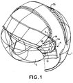
- une figure 1 représente un casque de pilote équipé d'un dispositif de fixation de visière selon l'invention ;
- une figure 2 représente en perspective une platine support de viseur de casque qui est destinée à être attachée sur l'extérieur de la coque d'un casque et sur laquelle sont fixées les articulations du dispositif de fixation de visière, l'une d'entre elles étant vue démontée ;
- une figure 3 représente en coupe une articulation du dispositif de fixation de visière ; et
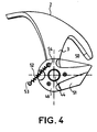
- une figure 4 est une vue d'une articulation du dispositif de fixation de visière équipée d'un ressort de traction permettant de rappeler la visière en position relevée.
- Le dispositif de fixation articulée qui va être décrit sert à l'attache d'une visière sur un casque de pilote prévu pour être équipé d'un viseur de casque.
- Le casque lui-même comporte une coque 1 de protection enveloppant le crâne à l'exception du visage. Cette coque 1 est surmontée d'une platine 2 en forme de calotte qui est recouverte d'un capotage 55 et qui supporte le tube générateur d'image et les éléments du système optique du viseur de casque projetant l'image du tube générateur d'image sur une zone semi-réfléchissante de la visière. La platine 2 est fixée sur le dessus de la coque 1 du casque grâce à des pattes de fixations boulonnées, un système de trous oblongs permettant d'ajuster la position relative de la calotte 2 par rapport à la coque 1 pour régler la position du viseur de casque par rapport aux yeux du porteur du casque. Elle présente deux pattes latérales 3 qui descendent le long de la coque 1 du casque à hauteur des tempes et portent les articulations 4 du dispositif de fixation articulée de la visière 5.
- La fixation de la visière 5 à la platine 2 et non à la coque 1 du casque permet de réunir en un ensemble à part les différents éléments du viseur de casque dont fait partie une zone semi-réfléchissante de la visière. Cela facilite les réglages des positionnements respectifs des éléments du système optique de projection du viseur de casque, permet de s'affranchir des problèmes posés par le manque de rigidité de la coque 1 du casque et simplifie la maintenance du viseur de casque.
- Chaque patte latérale 3 de la platine 2 porte à son extrémité une articulation 4 à pivot horizontal. Elle se termine, sensiblement à la verticale, par une oreille 10 qui forme une première pièce pivotante d'articulation solidaire du casque. Cette oreille 10 est percée d'un trou 11 pour un axe de pivot horizontal 12 présentant une tête circulaire aplatie 13 prolongée par une tige creuse 14. L'axe de pivot 12 est enfilé dans le trou 11 de l'oreille 10 par l'intérieur. Sa tête circulaire aplatie 13 vient se plaquer contre la paroi arrière de l'oreille 10 tandis que sa tige 14 dépasse à l'horizontal de la paroi avant de l'oreille 10. La tête circulaire aplatie 13 de l'axe de pivot 12 est percée à sa périphérie de trous 15 permettant sa fixation par vis à la patte 3 de la platine 2. La paroi avant de l'oreille 10 prend, autour de la base de la tige 14 de l'axe de pivot 12, la forme d'un plateau annulaire 16 servant de portée à l'articulation.
- Sur la tige creuse 14 de l'axe de pivot il vient tout d'abord une première rondelle 17, puis la deuxième pièce pivotante 18 de l'articulation qui est solidaire de la visière 5, une deuxième rondelle 19 et enfin un circlip 20 qui s'encliquette dans une rainure 21 pratiquée sur l'extérieur de l'extrémité de la tige creuse 14 de l'axe du pivot pour assurer l'assemblage des pièces de l'articulation.
- Les première et deuxième rondelles 17, 19 servent de cales d'épaisseur. Elles sont pelables. En ajustant leurs épaisseurs individuelles tout en leur conservant une épaisseur globale constante, on peut faire varier la position latérale de la deuxième pièce pivotante 18 de l'articulation par rapport à la platine 2 pour un réglage transversal fin de la position de la visière 5 par rapport au casque.
- La deuxième pièce pivotante 18 de l'articulation est enfilée sur la tige 14 de l'axe de pivot 12 par un orifice 25 bordé, du côté tourné vers l'oreille 10 de la platine, d'un plateau annulaire 26 servant de portée à l'articulation. Sensiblement verticale, elle est attachée à la visière par l'intermédiaire d'une patte intercalaire 27 qui lui est fixée par un système de brides plates 28, 29 boulonnées autorisant un ajustement de leurs positions respectives dans le plan vertical grâce à des orifices de perçage 30, 31, 32, 33 de formes oblongues en direction horizontale pour la bride plate 28 de la deuxième pièce pivotante 18 et en direction verticale pour la bride plate 29 de la patte intercalaire 27. Cet ajustement dans le plan vertical des positions relatives de la deuxième pièce pivotante 18 et de la patte intercalaire 27 permet un réglage fin en hauteur et profondeur de la position de la visière par rapport au casque lorsqu'elle est rabattue.
- La patte intercalaire 27 présente, au dos de sa bride plate 29 qui vient se fixer derrière la bride plate 28 de la deuxième pièce pivotante 18, une rainure 34 sensiblement verticale emprisonnant les écrous des boulons de fixation pour les bloquer en rotation tout en les laissant libres de coulisser pour l'ajustement des positions relatives des brides 28, 29. Elle se prolonge, du côté de la visière par une languette 35 percée de trous de rivetage 36, 37 prévus pour des rivets ancrés dans le côté de la visière.
- L'articulation 4 est pourvue d'un mécanisme de blocage par encliquetage dans une position particulière correspondant à la position rabattue de la visière. Ce mécanisme de blocage est constitué d'une rainure diamétrale 40 pratiquée dans la portée du plateau annulaire 26 de la deuxième pièce pivotante 18 de manière à réaliser une empreinte femelle, et d'une clavette 41 aux dimensions de la rainure diamétrale 40 montée élastiquement en relief sur la portée du plateau annulaire 16 de l'oreille 10 de la platine 2 de manière à réaliser une empreinte mâle.
- La clavette 41 est placée dans un logement rectangulaire à sa taille creusé au centre de la première rondelle 17 intercalée entre les deux pièces pivotantes 10, 18 de l'articulation. Solidaire en rotation de l'axe de pivot 12 et donc de la platine 2, elle se débat en profondeur le long de l'axe de pivot 12 au travers d'un trou diamétral 42 oblong traversant les parois de la tige creuse 14 de l'axe de pivot 12. Elle est fixée transversalement à l'extrémité d'une tirette 43 qui pénètre dans la tige 14 de l'axe de pivot au travers de la deuxième pièce pivotante 18 de l'articulation et qui prolonge la base d'un bouton poussoir 44 coiffant l'extrémité de la tige creuse de l'axe de pivot 12. Un ressort de compression 45 bobiné autour de la tirette 43 prend appui entre la base du bouton poussoir 44 et le flanc de la deuxième pièce pivotante 18 tourné vers l'extérieur de l'articulation et tend à extraire la tirette 43 de la tige creuse 14 de l'axe de pivot et à rapprocher la clavette 41 de la partie rainurée de la deuxième pièce pivotante 18 de l'articulation.
- Au cours d'une manoeuvre de la visière, la clavette 41 qui est solidaire en rotation du casque glisse sur la portée du plateau annulaire 26 de la deuxième pièce pivotante 18 solidaire en rotation de la visière jusqu'à ce qu'elle se retrouve alignée avec la rainure diamétrale 40 ce qui se produit lorsque la visière parvient dans la position rabattue convenant au viseur de casque. Elle s'encliquette alors dans la rainure 40 bloquant l'articulation.
- Pour relever la visière à partir de sa position rabattue, il faut, avant de basculer la visière, appuyer sur le bouton poussoir 44 pour extraire la clavette 41 de la rainure 40 et débloquer l'articulation.
- La deuxième pièce pivotante 18 et la patte intercalaire 27 qui la fixe à la visière sont capotées par une manette 46 en forme de coquille traversée par le bouton poussoir 44. Cette manette 46 est vissée sur des pattes 47, 48, 49 que présente la deuxième pièce pivotante 18 à la périphérie de son orifice 25 traversé par l'axe de pivot 12. Elle possède sur sa surface extérieure deux cannelures 50, 51 sensiblement horizontales allant de la visière à l'axe de pivot 12 de l'articulation et facilitant sa prise en main. Elle permet de basculer la visière sans avoir à la toucher.
- Un ressort de traction 52 plus particulièrement visible sur la figure 4, accroché entre un point d'ancrage 53 sur la coque 1 du casque et la vis supérieure de fixation 54 de la manette 46 rappelle la visière en position relevée de sorte qu'il suffit au porteur du casque pour relever sa visière d'appuyer sur les boutons poussoirs 44 de déblocage des articulations.
Claims (10)
- Dispositif de fixation articulée d'une visière (5) sur un casque (1, 2) comportant deux articulations à pivot qui attachent les côtés de la visière (5) aux parois latérales du casque (1, 2) en permettant à la visière (5) de pivoter entre une position rabattue devant les yeux du porteur de casque et une position escamotée dégageant le visage du porteur du casque, dont l'une au moins est pourvue d'un mécanisme de blocage (40, 41) par encliquetage en position rabattue et de moyens de déverrouillage (43, 44, 45) actionnables à volonté pour relâcher le mécanisme de blocage et qui comportent chacune deux pièces (10, 18) l'une (10) fixée au casque, l'autre (18) fixée à la visière, pivotant l'une par rapport à l'autre autour d'un axe de pivot (12) avec des surfaces annulaires en contact dites portées, caractérisé en ce que ledit mécanisme de blocage par encliquetage est constitué par une rainure diamétrale (40) pratiquée dans l'une des portées (26) dite portée femelle et d'une clavette (41) escamotable, aux dimensions de la rainure (40), passée au travers de l'axe de pivot (12) et montée élastiquement en relief sur l'autre portée (16) en regard dite portée mâle de l'une au moins des articulations.
- Dispositif selon la revendication 1, caractérisé en ce que la clavette (41) se débat en profondeur selon l'axe de pivot (12) dans un trou diamétral (42) à section oblongue percé dans l'axe de pivot (12) qui est solidaire en rotation de la portée mâle (16).
- Dispositif selon la revendication 2, caractérisé en ce que les moyens de déverrouillage comporte un bouton poussoir (44) prolongé à sa base par une tirette (43) qui pénètre dans l'axe creux du pivot (12) au travers de la pièce pivotante (18) supportant la portée femelle (26) et qui maintient la clavette (41) fixée transversalement à son extrémité, et un ressort de compression (45) agissant sur le bouton poussoir (44) de manière à extraire sa tirette (43) de l'axe creux de pivot (12) et à rapprocher la clavette (41) de la portée femelle (26).
- Dispositif selon la revendication 1, caractérisé en ce que ses articulations à pivot comportent des cales d'épaisseur pelables (17, 19) disposées sur l'axe de pivot (12), de part et d'autre de la pièce pivotante (18) fixée à la visière (5), lesdites cales (17, 19) permettant, en ajustant leurs épaisseurs individuelles tout en conservant leur épaisseur globale, un réglage transversal fin de la position de la visière (5) par rapport au casque (1, 2).
- Dispositif selon la revendication 1, caractérisé en ce que la pièce (18) de ses articulations solidaire en rotation de la visière (5) est fixée à la visière (5) par l'intermédiaire d'une patte intercalaire (27) à laquelle elle est attachée par boulonnage de deux brides plates (28, 29) percées de trous oblongs (30, 31, 32, 33) permettant un réglage, dans un plan perpendiculaire à l'axe de pivotement des articulations (4), de la position de la visière (5) par rapport au casque (1, 2) lorsqu'elle est rabattue.
- Dispositif selon la revendication 1, caractérisé en ce que la pièce pivotante (18) fixée à la visière (5) de l'une au moins de ses articulations (4) est surmontée d'une manette (46) permettant de manoeuvrer la visière (5) sans avoir à la toucher.
- Dispositif selon la revendication 6, caractérisé en ce que ladite manette (46) a la forme d'une coquille présentant sur sa face extérieure des cannelures (50, 51) facilitant sa préhension.
- Dispositif selon la revendication 3, caractérisé en ce que ledit bouton poussoir (44) qui coiffe l'axe de pivot (12) est logé dans une manette (46) qui est montée sur la pièce pivotante (18) fixée à la visière (5) et qui permet de manoeuvrer la visière sans avoir à la toucher.
- Dispositif selon la revendication 1, caractérisé en ce qu'il comporte des moyens élastiques (52) agissant entre les deux pièces pivotantes (10, 18) de l'une au moins de ses articulations (4) pour rappeler la visière (5) en position relevée.
- Dispositif selon la revendication 1, avec des articulations (4) à pivot présentant deux pièces (10, 18) pivotant l'une par rapport à l'autre l'une (10) fixée au casque (1, 2), l'autre (18) fixée à la visière (5), caractérisé en ce qu'il comporte des moyens élastiques (52) agissant entre les deux pièces pivotantes (10, 18) de l'une au moins des articulations (4) pour rappeler la visière (5) en position relevée.
Applications Claiming Priority (2)
| Application Number | Priority Date | Filing Date | Title |
|---|---|---|---|
| FR9306734A FR2705871B1 (fr) | 1993-06-04 | 1993-06-04 | Dispositif de fixation articulée d'une visière sur un casque. |
| FR9306734 | 1993-06-04 |
Publications (2)
| Publication Number | Publication Date |
|---|---|
| EP0628261A1 EP0628261A1 (fr) | 1994-12-14 |
| EP0628261B1 true EP0628261B1 (fr) | 1997-08-06 |
Family
ID=9447784
Family Applications (1)
| Application Number | Title | Priority Date | Filing Date |
|---|---|---|---|
| EP19940401233 Expired - Lifetime EP0628261B1 (fr) | 1993-06-04 | 1994-06-03 | Dispositif de fixation articulée d'une visière sur un casque |
Country Status (3)
| Country | Link |
|---|---|
| EP (1) | EP0628261B1 (fr) |
| DE (1) | DE69404761T2 (fr) |
| FR (1) | FR2705871B1 (fr) |
Families Citing this family (6)
| Publication number | Priority date | Publication date | Assignee | Title |
|---|---|---|---|---|
| EP0783842B1 (fr) * | 1995-12-22 | 2000-05-24 | E.D.C. Sa | Dispositif pour verrouiller en position de fermeture la visière d'un casque pour motocyclistes et similaires |
| US6195206B1 (en) | 1998-01-13 | 2001-02-27 | Elbit Systems Ltd. | Optical system for day and night use |
| CA2448126A1 (fr) * | 2001-05-23 | 2003-01-16 | Scott Technologies, Inc. | Masque pivotant |
| ATE338481T1 (de) | 2002-09-12 | 2006-09-15 | Opticos Srl | Vorrichtung zum befestigen einer visierscheibe an einem helm |
| US7225471B2 (en) * | 2004-07-23 | 2007-06-05 | Gentex Corporation | Removable optical assembly for a helmet |
| CN113974253B (zh) * | 2021-09-22 | 2023-06-23 | 天津(滨海)人工智能军民融合创新中心 | 一种头盔上头显机构的多向调节固定装置 |
Family Cites Families (7)
| Publication number | Priority date | Publication date | Assignee | Title |
|---|---|---|---|---|
| FR1446416A (fr) * | 1965-06-09 | 1966-07-22 | Optique Scient L | Casque de pilote d'avion avec mécanisme de manoeuvre et de verrouillage de l'écrande protection |
| US3636565A (en) * | 1970-01-29 | 1972-01-25 | Gentex Corp | Universal dual visor assembly for helmets |
| GB8628864D0 (en) * | 1986-12-03 | 1987-01-28 | Helmets Ltd | Helmets |
| JPH02289105A (ja) * | 1989-04-25 | 1990-11-29 | Shoei Kako Kk | ヘルメット |
| DE9007028U1 (de) * | 1990-06-23 | 1990-08-30 | Uvex Winter Optik GmbH, 8510 Fürth | Schutzhelm, insbesondere Motorradschutzhelm |
| FR2667765A1 (fr) * | 1990-10-16 | 1992-04-17 | Sextant Avionique | Dispositif de blocage d'une visiere et casque equipe d'au moins un tel dispositif. |
| US5177816A (en) * | 1991-12-10 | 1993-01-12 | The United States Of America As Represented By The Secretary Of The Navy | Helmet visor support apparatus |
-
1993
- 1993-06-04 FR FR9306734A patent/FR2705871B1/fr not_active Expired - Fee Related
-
1994
- 1994-06-03 DE DE1994604761 patent/DE69404761T2/de not_active Expired - Fee Related
- 1994-06-03 EP EP19940401233 patent/EP0628261B1/fr not_active Expired - Lifetime
Also Published As
| Publication number | Publication date |
|---|---|
| EP0628261A1 (fr) | 1994-12-14 |
| DE69404761T2 (de) | 1998-01-08 |
| FR2705871B1 (fr) | 1995-07-21 |
| DE69404761D1 (de) | 1997-09-11 |
| FR2705871A1 (fr) | 1994-12-09 |
Similar Documents
| Publication | Publication Date | Title |
|---|---|---|
| EP0639944A1 (fr) | Dispositif de fixation d'une paire de lunettes a un couvre-chef | |
| CA2349764C (fr) | Perfectionnement pour casque de protection | |
| CA1132383A (fr) | Support pour face de monture de lunettes, en particulier pour emploi sous casque | |
| EP0671646B1 (fr) | Dispositif d'accrochage mécanique d'un système de visualisation sur un casque | |
| FR2595212A1 (fr) | Casque de protection | |
| FR2578724A1 (fr) | Casque, notamment pour pilotes d'avions | |
| EP0253864B1 (fr) | Systeme aerodynamique et antibuee de coque et d'ecran de vision d'un casque de protection | |
| EP0702906B1 (fr) | Paire d'articulations à manoeuvres synchronisées pour la fixation d'une visière escamotable sur un casque | |
| EP0134595B1 (fr) | Chaussure de ski | |
| EP1818458B1 (fr) | Dispositif permettant d'obturer un cadre, comprenant un panneau monté articulé amovible sur le cadre | |
| EP0402242B1 (fr) | Cassette à miroir pour pare-soleil, notamment dans un habitacle d'automobile | |
| EP0838711A1 (fr) | Monture de lunettes en fil métallique | |
| EP0628261A1 (fr) | Dispositif de fixation articulée d'une visière sur un casque | |
| EP2919727B1 (fr) | Masque à écran amovible | |
| FR2674487A1 (fr) | Dispositif de montage a pivotement d'un element optique de projecteur de vehicule automobile. | |
| CA2502936C (fr) | Dispositif de fixation par verrouillage d'un appareil destine a etre monte dans un rack | |
| EP1740066B1 (fr) | Perfectionnement pour casque de protection | |
| EP0663154B1 (fr) | Chaussure de ski à inclinaison de tige variable | |
| FR2682653A1 (fr) | Perfectionnements aux supports et porte charge pour vehicules. | |
| EP0486411A1 (fr) | Dispositif de sécurité pour chemin de circulation | |
| FR2750299A1 (fr) | Casque de protection comportant un ecran facial escamotable a l'interieur du casque | |
| EP0724052B1 (fr) | Poignée de porte de véhicule automobile à montage rapide par système coin-came | |
| FR2517878A1 (fr) | Porte-fusibles pour vehicule automobile | |
| EP4296760B1 (fr) | Paire de lunettes a pion de verrouillage et procede de montage correspondant | |
| CA1126774A (fr) | Ensemble de fixation d'une chaussure a un ski |
Legal Events
| Date | Code | Title | Description |
|---|---|---|---|
| PUAI | Public reference made under article 153(3) epc to a published international application that has entered the european phase |
Free format text: ORIGINAL CODE: 0009012 |
|
| AK | Designated contracting states |
Kind code of ref document: A1 Designated state(s): DE |
|
| 17P | Request for examination filed |
Effective date: 19950123 |
|
| 17Q | First examination report despatched |
Effective date: 19960412 |
|
| GRAG | Despatch of communication of intention to grant |
Free format text: ORIGINAL CODE: EPIDOS AGRA |
|
| GRAH | Despatch of communication of intention to grant a patent |
Free format text: ORIGINAL CODE: EPIDOS IGRA |
|
| GRAH | Despatch of communication of intention to grant a patent |
Free format text: ORIGINAL CODE: EPIDOS IGRA |
|
| GRAA | (expected) grant |
Free format text: ORIGINAL CODE: 0009210 |
|
| AK | Designated contracting states |
Kind code of ref document: B1 Designated state(s): DE |
|
| REF | Corresponds to: |
Ref document number: 69404761 Country of ref document: DE Date of ref document: 19970911 |
|
| PLBE | No opposition filed within time limit |
Free format text: ORIGINAL CODE: 0009261 |
|
| STAA | Information on the status of an ep patent application or granted ep patent |
Free format text: STATUS: NO OPPOSITION FILED WITHIN TIME LIMIT |
|
| 26N | No opposition filed | ||
| PGFP | Annual fee paid to national office [announced via postgrant information from national office to epo] |
Ref country code: DE Payment date: 20060601 Year of fee payment: 13 |
|
| PG25 | Lapsed in a contracting state [announced via postgrant information from national office to epo] |
Ref country code: DE Free format text: LAPSE BECAUSE OF NON-PAYMENT OF DUE FEES Effective date: 20080101 |