EP0624322B1 - Ventilating shoes - Google Patents
Ventilating shoes Download PDFInfo
- Publication number
- EP0624322B1 EP0624322B1 EP94401058A EP94401058A EP0624322B1 EP 0624322 B1 EP0624322 B1 EP 0624322B1 EP 94401058 A EP94401058 A EP 94401058A EP 94401058 A EP94401058 A EP 94401058A EP 0624322 B1 EP0624322 B1 EP 0624322B1
- Authority
- EP
- European Patent Office
- Prior art keywords
- pump
- shoe
- ventilating
- unidirectional valve
- sole
- Prior art date
- Legal status (The legal status is an assumption and is not a legal conclusion. Google has not performed a legal analysis and makes no representation as to the accuracy of the status listed.)
- Expired - Lifetime
Links
- 239000000463 material Substances 0.000 claims description 11
- 238000009423 ventilation Methods 0.000 claims description 11
- 230000005540 biological transmission Effects 0.000 claims description 10
- 230000033001 locomotion Effects 0.000 claims description 9
- 229920001971 elastomer Polymers 0.000 claims description 6
- 229920005989 resin Polymers 0.000 claims description 6
- 239000011347 resin Substances 0.000 claims description 6
- 239000005060 rubber Substances 0.000 claims description 6
- 230000006835 compression Effects 0.000 claims description 5
- 238000007906 compression Methods 0.000 claims description 5
- 239000013013 elastic material Substances 0.000 claims description 5
- -1 polyethylene Polymers 0.000 claims description 4
- 229920003051 synthetic elastomer Polymers 0.000 claims description 4
- 239000005061 synthetic rubber Substances 0.000 claims description 4
- 244000043261 Hevea brasiliensis Species 0.000 claims description 3
- 229920003052 natural elastomer Polymers 0.000 claims description 3
- 229920001194 natural rubber Polymers 0.000 claims description 3
- 239000004698 Polyethylene Substances 0.000 claims description 2
- 229920000573 polyethylene Polymers 0.000 claims description 2
- 229920003048 styrene butadiene rubber Polymers 0.000 claims description 2
- 229920003225 polyurethane elastomer Polymers 0.000 claims 1
- 238000010586 diagram Methods 0.000 description 6
- 238000005086 pumping Methods 0.000 description 4
- 210000002683 foot Anatomy 0.000 description 3
- 239000007779 soft material Substances 0.000 description 3
- 239000004743 Polypropylene Substances 0.000 description 2
- 239000000428 dust Substances 0.000 description 2
- 229920001155 polypropylene Polymers 0.000 description 2
- 229920000915 polyvinyl chloride Polymers 0.000 description 2
- 239000004800 polyvinyl chloride Substances 0.000 description 2
- 235000017166 Bambusa arundinacea Nutrition 0.000 description 1
- 235000017491 Bambusa tulda Nutrition 0.000 description 1
- 241001330002 Bambuseae Species 0.000 description 1
- 235000015334 Phyllostachys viridis Nutrition 0.000 description 1
- 229920000122 acrylonitrile butadiene styrene Polymers 0.000 description 1
- 230000009471 action Effects 0.000 description 1
- 239000011425 bamboo Substances 0.000 description 1
- 238000007599 discharging Methods 0.000 description 1
- 238000001914 filtration Methods 0.000 description 1
- 239000003292 glue Substances 0.000 description 1
- 238000002347 injection Methods 0.000 description 1
- 239000007924 injection Substances 0.000 description 1
- 229920001684 low density polyethylene Polymers 0.000 description 1
- 239000004702 low-density polyethylene Substances 0.000 description 1
- 238000004519 manufacturing process Methods 0.000 description 1
- 238000000034 method Methods 0.000 description 1
- 239000000203 mixture Substances 0.000 description 1
- 230000004048 modification Effects 0.000 description 1
- 238000012986 modification Methods 0.000 description 1
- 238000000465 moulding Methods 0.000 description 1
- 229920005749 polyurethane resin Polymers 0.000 description 1
- 230000008569 process Effects 0.000 description 1
- 210000004233 talus Anatomy 0.000 description 1
- 239000002023 wood Substances 0.000 description 1
Images


Classifications
-
- A—HUMAN NECESSITIES
- A43—FOOTWEAR
- A43B—CHARACTERISTIC FEATURES OF FOOTWEAR; PARTS OF FOOTWEAR
- A43B7/00—Footwear with health or hygienic arrangements
- A43B7/06—Footwear with health or hygienic arrangements ventilated
- A43B7/08—Footwear with health or hygienic arrangements ventilated with air-holes, with or without closures
- A43B7/082—Footwear with health or hygienic arrangements ventilated with air-holes, with or without closures the air being expelled to the outside
Definitions
- the present invention relates to ventilating shoes having a ventilator for ventilating inside of a shoe during ambulatory movement.
- US patent 4,860,463 describes a ventilating shoe having a ventilator wherein pumping action is achieved using a block of material, in the shoe heel, having a number of holes which are compressed on application of heel pressure and re-expand on release of heel pressure. Two pairs of one-way valves control suction of air from the toe region of the shoe (on release of heel pressure) and expulsion of air to the outside (on application of heel pressure).
- US patent 5,068,981 describes a heel chamber body for a ventilating shoe in which a pouch-shaped chamber is defined by a housing having three openings in its sides. An inlet valve is provided in one of the three openings and respective outlet valves are provided in the other two openings. Each valve consists of a pair of perforated plates with a displaceable bar moving to-and-fro between them. Heel pressure compresses the pouch-shaped chamber forcing air out of the two outlet valves. On release of heel pressure a spring inside the heel chamber encourages the chamber to adopt its original shape thereby sucking air in through the inlet valve.
- a ventilating shoe including a ventilator which is operated by ambulatory movement, and which comprises a valve arrangement which includes only first and second unidirectional valves
- the ventilating shoe comprising: an air groove formed between an insole and a sole of the shoe, said insole having a plurality of ventilating holes formed therein and said insole having a strength so as to function as a component of the shoe while having said plurality of ventilating holes therein and said sole having a strength so as to function as a component of the shoe; a pump which is incorporated into a cylindrical bellows shape using a resin material and is provided inside a heel portion of the shoe so the cylindrical bellows is pressurized and compressed by heel pressure, and the cylindrical bellows expands to an original shape thereof upon releasing of the heel pressure; said first unidirectional valve which comprises a hollow body formed from elastic material, said hollow body of said first unidirectional valve being substantially in a bullet shape having a tapering head which has at least a single
- a positive pressure generated by the pump in the heel closes the first unidirectional valve when a heel pressure of the ventilating shoes is generated in the ambulatory movement, and air is released to the outside via the second unidirectional valve.
- the heel pressure is released, an inner negative pressure is generated, and the second unidirectional valve is closed, while the first unidirectional valve is opened.
- the air inside the shoe is taken into the pump via the air grooves having a plurality of ventilating holes connected to the first unidirectional valve.
- the space formed in the sole is efficiently used by containing the pump in the heel portion which is incorporated into the shoe sole, and embedding the first and second unidirectional valves in the space at the arch of foot on the sole.
- a ventilating function can be maintained for a long time by preventing dust into the first unidirectional valve by a filtering means.
- Fig. 1 is a cross-sectional view of a shoe of the embodiment.
- the shoe which is mainly composed of sole 2, insole 3 and upper 1 fits to the foot 4.
- the insole 3 has a plurality of ventilating holes 5 around the toe tip, and ventilation is performed by these ventilating holes 5.
- the ventilating holes 5 are placed so as to correspond to the positions of the air holes 12 provided in the sole 2.
- the air holes 12 are integrated at the meeting portion 12a (Fig. 3A).
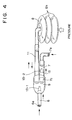
- the ventilator takes the air inside the shoe in the arrow's direction via the inlet 6a at the meeting portion 12a, while exhausting the air inside the shoe to the outside via the exhaustion unit 7 having an outlet 7a at the tip of the exhaustion unit 7.
- a cylindrical bellows pump 8 having a plurality of folds connects the inlet 6a and outlet 7a respectively via the air transmission unit 11.
- the sole with the above-described constitution is made into the heel by using polyurethane resin, natural rubber, synthetic rubber, mixture of natural rubber and synthetic rubber, and sponge rubber and RB rubber having a predetermined strength.
- the heel portion can be comprised of material different from the sole.
- Fig. 2 is a cross-sectional view where the main body of the pump 8 is contained in the internal space of the heel.
- the heel portion is comprised of a concavity 2a, the space having a flat bottom in a substantially circle shape to contain the pump 8, a convexity 2b, in a substantially circle shape, located beneath the concavity 2a projected by thickness T, and a ring-shape groove 2c provided around the convexity 2b.
- Fig. 3A is a perspective view of the sole 2 without the upper 1 and insole 3.
- Fig. 3B is a diagram illustrating the arrangement of the pipes of Fig. 3A. Since the air grooves 12 are connected to a plurality of ventilating holes 5 of the insole 3 when the components are assembled as a shoe, an air flow passage is formed, and the air inside of the shoe is taken from the rear end of the air grooves 12. At the rear end of the air groove 12, the above-described inlet 6a is provided, and connected to the joint 9, pump 8 and outlet 7a. A plurality of concavities 2d (Fig. 3A) on the sides of the joint 9 are made to reduce the weight of the shoe.
- Fig. 4 shows the assembled ventilator before being installed in the sole 2.
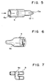
- the suction unit 6 having the inlet 6a at one end is shown in detail in Fig. 5.
- the suction unit 6 is formed as a pipe comprising of hard material such as polyvinyl chloride, ABS resin, polypropylene, wood or bamboo.
- a unidirectional valve 13-1 is inserted on the other end of the suction unit 6a.
- the detail of the unidirectional valve 13-1 is shown in Fig. 12.
- the air valve 13-1 is formed of elastic material such as rubber, soft polyvinyl chloride and AR synthetic rubber whose shape like a bullet.
- the base of the unidirectional valve 13-1 is open, and the tip is provided with the slit 13a which functions as a valve.
- This slit 13a can be a single slit or cross shape slit from the view point of the head of the unidirectional valve 13-1, or a single slant slit as shown in fig. 13.
- Figs. 6 and 7 are the detail of the joint 9.
- the joint 9 includes a branch unit 9a, as shown in Figs. 6 and 7, which unites the suction unit 6, exhaustion unit 7 and air transmission unit 11. After the assembling, these units are assembled to maintain air tightness.
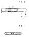
- the exhaustion unit 7 inserted into one end of the branch unit 9a is described with reference to Fig. 8.
- the main body of the exhaustion unit 7 is a pipe made from soft material.
- the soft pipe 7c to which the unidirectional valve 13-2 is inserted is further inserted into one branch of the branch unit 9a.
- the unidirectional valve 13-2 is of the same type as that of the unidirectional valve 13-1.
- the discharge pipe 7b made from soft material is inserted into the other end of the exhaustion unit 7.
- the discharge pipe 7b is bent so as to discharge air to the bottom or side of the shoe sole, and its opening is outlet 7a.
- the air transmission unit 11 is shown in Fig. 9.
- the air transmission unit 11 which is inserted into the other branch of the branch unit 9a is made from soft material, and performs air transmission between the pump 8 and the joint 9.
- the detail of the pump 8 is shown in Figs. 10 and 11.
- the pump 8 is made from elastic rubber or recoverable materials such a polyethylene, "LINIREX, L-LDPE” (registered trademark of HIHON SEKIYU KAGAKU), polypropylene and styrene butadiene rubber.
- the pump 8 is cylindrical in shape having three folds 8h which contain air.
- the bottom of the pump 8 is closed, and the upper portion is a pipe shape.
- the pipe has an opening 8a, and is inserted into the transmission unit 11.
- the pump of Fig. 11 is similar to the pump of Fig. 10. However, Fig. 11 differs from Fig. 10 in that the bottom is opened and closed by the separate cover 8c by glue or similar means, after the spring 8b is set inside of the pump 8.
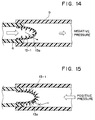
- Fig. 14 is a diagram illustrating the case where the unidirectional valve 13-1 is subject to negative pressure.
- the air flows through the opening of the unidirectional valve 13-1, that is, from the inside of suction unit 6 to the outside, but does not flow from the outside to the inside since the pressure inside is greater.
- the unidirectional valve 13-1 is a bullet shape. In this shape, if the air inside of the valve is pressurized, a force to open the slit 13a to the outside is generated, and air flows out.
- Fig. 15 is a diagram illustrating the case where the unidirectional valve 13-1 is subject to positive pressure, i.e. outside pressure is greater.
- unidirectional valve 13-1 Since the unidirectional valve 13-1 is a bullet shape, when the positive pressure acts on the outside of the valve, a force to close the slit 13a is generated, and the air inside the valve 13-1 is prevented from flowing out. As the pressure increases, the force to open/close the slit 13a increases.
- the operating principal of unidirectional valve 13-2 is similar to that of unidirectional valve 13-1. As described above, both the first unidirectional valve and second unidirectional valve are constituted almost in the same manner.
- Ventilation is performed when the air flows only in one direction by using unidirectional valve 13-1 and 13-2. That is, in the joint 9, since unidirectional valve 13-1 connected to the suction unit 6 is arranged to close to positive pressure, while the unidirectional valve 13-2 connected to the exhaustion unit 7 is arranged to open when the pump 8 is pressed, air can be released to the atmosphere via the outlet 7a. Furthermore, when the pressure in the pump 8 is zero, the unidirectional valve 13-2 is automatically closed by elasticity.
- the unidirectional ventilation between the upper 1 and foot 4 is performed via the plurality of ventilating holes 5 and the corresponding air grooves 12 of the sole 2. Air in the shoe is sucked by the pump 8 from the inlet 6a, and discharged to the outside by the outlet 7a. Furthermore, ventilation around the toe tip can be efficiently performed.
- the amount of ventilated air depends on the capability of the pump 8, however, air of approximately 2-3 cm 3 can be exchanged per pumping. In case of men's shoes, the capacity of the internal space of the shoe varies from 7-8 cm 3 to 10-15cm 3 at most. Accordingly, in several steps, the entire volume of air in the shoes can be exchanged.
- Fig. 16 is a partial sectional view of the assembled ventilator contained in the sole 2. The description of the structural components which have been already described is not needed. However, a filter 20 is inserted into the inlet 6a to prevent the pipe from choking with dust. As a result, the slit 13a is protected from the choking, and can function properly for a long period of time.
- each part can be produced simply by injection resin molding.
- men's shoes whose upper is below the anklebone are described.
- this does not impose a limitation upon the invention.
- the invention can be applied to boots, sports shoes, mountain-climbing boots, women's shoes and children's shoes.
- the present invention is not limited to the above-described embodiments.
- a shoe has a ventilator for discharging the air in a shoe by pumping means driven by ambulatory movement
- various modifications are possible.
- the ventilator is also not limited to a separate pump, for pump and valves can be incorporated into one unit and contained on the heel portion to reduce the size.
Landscapes
- Health & Medical Sciences (AREA)
- Epidemiology (AREA)
- General Health & Medical Sciences (AREA)
- Public Health (AREA)
- Footwear And Its Accessory, Manufacturing Method And Apparatuses (AREA)
Applications Claiming Priority (4)
| Application Number | Priority Date | Filing Date | Title |
|---|---|---|---|
| JP11027993 | 1993-05-12 | ||
| JP110279/93 | 1993-05-12 | ||
| JP6043550A JPH0723802A (ja) | 1993-05-12 | 1994-03-15 | 換気靴 |
| JP43550/94 | 1994-03-15 |
Publications (2)
| Publication Number | Publication Date |
|---|---|
| EP0624322A1 EP0624322A1 (en) | 1994-11-17 |
| EP0624322B1 true EP0624322B1 (en) | 1997-08-06 |
Family
ID=26383338
Family Applications (1)
| Application Number | Title | Priority Date | Filing Date |
|---|---|---|---|
| EP94401058A Expired - Lifetime EP0624322B1 (en) | 1993-05-12 | 1994-05-11 | Ventilating shoes |
Country Status (8)
| Country | Link |
|---|---|
| US (1) | US5505010A (enExample) |
| EP (1) | EP0624322B1 (enExample) |
| JP (1) | JPH0723802A (enExample) |
| KR (1) | KR970009625B1 (enExample) |
| CN (1) | CN1100615A (enExample) |
| DE (1) | DE69404737T2 (enExample) |
| ES (1) | ES2106466T3 (enExample) |
| TW (1) | TW239068B (enExample) |
Families Citing this family (68)
| Publication number | Priority date | Publication date | Assignee | Title |
|---|---|---|---|---|
| US6230501B1 (en) | 1994-04-14 | 2001-05-15 | Promxd Technology, Inc. | Ergonomic systems and methods providing intelligent adaptive surfaces and temperature control |
| US5845417A (en) * | 1994-10-19 | 1998-12-08 | Rusty A. Reed | Air cooled shoe having an air exhaust pump |
| FR2727606B1 (fr) * | 1994-12-02 | 1997-01-17 | Vermonet Christian | Dispositif de ventilation pour article chaussant et procede de fabrication |
| WO1996024267A1 (en) * | 1995-02-06 | 1996-08-15 | Jeong Kun Yoon | Shoes excellent in ventilation |
| DE19524565A1 (de) * | 1995-07-06 | 1997-01-09 | Bayer Ag | Ventilierter Straßenschuh |
| US5675914A (en) * | 1995-11-13 | 1997-10-14 | The Rockport Company, Inc. | Air circulating footbed |
| CN2261161Y (zh) * | 1996-12-06 | 1997-09-03 | 陈志红 | 三气室助力鞋底 |
| US6125556A (en) * | 1997-06-20 | 2000-10-03 | Peckler; Stephen N. | Golf shoe with high liquid pressure spike ejection |
| US6041519A (en) * | 1997-06-25 | 2000-03-28 | Cheng; Peter S. C. | Air-circulating, shock-absorbing shoe structures |
| US5983525A (en) * | 1998-04-16 | 1999-11-16 | Brown; Leon T. | Vented shoe sole |
| GB2339670A (en) * | 1998-07-22 | 2000-02-09 | David Holburn | Internal footwear cooling and moisture expelling device |
| US7219449B1 (en) | 1999-05-03 | 2007-05-22 | Promdx Technology, Inc. | Adaptively controlled footwear |
| CA2279738A1 (en) | 1999-08-04 | 2001-02-04 | Opal Limited | Ventilated footwear |
| US6463679B1 (en) * | 1999-10-21 | 2002-10-15 | Yamamoto Limited | Forced ventilation system inside soles |
| KR200180545Y1 (ko) * | 1999-11-26 | 2000-05-01 | 유용돈 | 체력단련용 운동화. |
| IT1311623B1 (it) | 1999-12-30 | 2002-03-14 | Franca Losego | Suola ventilata. |
| EP1127505B1 (en) * | 2000-02-28 | 2004-08-11 | STONEFLY S.p.A. | Forced air circulation shoe structure |
| JP3081377U (ja) * | 2001-04-25 | 2001-11-02 | 請吉 山本 | 靴底と同靴底を用いた靴 |
| KR20010079184A (ko) * | 2001-06-20 | 2001-08-22 | 최기수 | 구두굽 |
| US20020194747A1 (en) * | 2001-06-21 | 2002-12-26 | Passke Joel L. | Footwear with bladder filter |
| GB2382017A (en) * | 2001-11-16 | 2003-05-21 | Clark C & J Int Ltd | Air channel arrangement in ventilated footwear |
| ES2257106B1 (es) * | 2002-07-30 | 2007-06-16 | Stoil Radkov Pochileev | Zapato con bomba aerea. |
| US6990752B2 (en) * | 2002-08-01 | 2006-01-31 | Louis Garneau Sports Inc. | Bicycle shoe with ventilating sole |
| CA100351S (en) | 2002-08-16 | 2003-12-15 | Opal Ltd | Insole |
| US6889451B2 (en) * | 2003-04-23 | 2005-05-10 | Mike, Inc. | Fluid system with internal filter |
| US7080467B2 (en) | 2003-06-27 | 2006-07-25 | Reebok International Ltd. | Cushioning sole for an article of footwear |
| USD495127S1 (en) | 2003-06-27 | 2004-08-31 | Reebok International Ltd. | Portion of a midsole |
| US7409780B2 (en) * | 2003-07-21 | 2008-08-12 | Reebok International Ltd. | Bellowed chamber for a shoe |
| US7426793B2 (en) * | 2004-01-21 | 2008-09-23 | Ll International Shoe Co., Inc. | Footwear shock absorbing and ventilating apparatus |
| US20050178023A1 (en) * | 2004-02-17 | 2005-08-18 | Hammonds Jesse M. | Self-ventilating shoe assembly |
| CN100462020C (zh) * | 2004-03-08 | 2009-02-18 | 陈壹敏 | 换气跟式皮鞋 |
| US7234250B2 (en) * | 2005-02-07 | 2007-06-26 | Stacy Renee Fogarty | Convertible traction shoes |
| US8474153B2 (en) * | 2005-09-15 | 2013-07-02 | Alfred Cloutier Ltée | Adaptable shoe cover |
| CN1819782A (zh) * | 2005-09-16 | 2006-08-16 | 斯普林泰姆发展有限公司 | 鞋子的通气系统及设备 |
| ITFI20050233A1 (it) * | 2005-11-15 | 2007-05-16 | You Cing Miao | Calzatura con dispositivo di aerazione |
| WO2007148910A1 (en) * | 2006-06-20 | 2007-12-27 | Doctor For Doctor Co., Ltd. | Shoes and shoes insole capable of buffering shock by air circulation |
| US7681329B2 (en) * | 2006-07-26 | 2010-03-23 | Fu Victor | Ventilated footwear |
| KR200431310Y1 (ko) * | 2006-08-23 | 2006-11-23 | 오혜성 | 신발의 공기 공급장치 |
| RU2339284C2 (ru) * | 2006-11-15 | 2008-11-27 | Российский заочный институт текстильной и легкой промышленности | Обувь с принудительной вентиляцией |
| US8336230B2 (en) * | 2006-12-01 | 2012-12-25 | Nike, Inc. | Article of footwear for weight lifting |
| US20120110871A1 (en) * | 2007-02-13 | 2012-05-10 | Alexander Elnekaveh | Resilient Shoe With Pivoting Sole |
| US20100095553A1 (en) * | 2007-02-13 | 2010-04-22 | Alexander Elnekaveh | Resilient sports shoe |
| US20080189986A1 (en) * | 2007-02-13 | 2008-08-14 | Alexander Elnekaveh | Ventilated and resilient shoe apparatus and system |
| KR100812135B1 (ko) * | 2007-03-12 | 2008-03-12 | 양영욱 | 항균 기능을 갖는 신발용 공기순환식 깔창 |
| US20080229623A1 (en) * | 2007-03-23 | 2008-09-25 | Giorgio Ferretti | Aeration system and device for shoes |
| RU2343810C1 (ru) * | 2007-04-13 | 2009-01-20 | Федеральное агентство по образованию Государственное образовательное учреждение высшего профессионального образования Российский заочный институт текстильной и легкой промышленности | Вентилируемая обувь с камерой разрежения |
| RU2357629C2 (ru) * | 2007-06-05 | 2009-06-10 | Федеральное агентство по образованию Государственное образовательное учреждение высшего профессионального образования "Российский заочный институт текстильной и легкой промышленности" | Обувь с принудительной вентиляцией и амортизацией |
| KR100842431B1 (ko) * | 2007-06-25 | 2008-07-01 | 이재명 | 신발용 안창 |
| US20090151203A1 (en) * | 2007-12-14 | 2009-06-18 | Boyer David S | Ventilating shoe |
| JP4648472B2 (ja) * | 2008-08-01 | 2011-03-09 | 績 三上 | 逆止弁 |
| US20100139127A1 (en) * | 2008-12-08 | 2010-06-10 | Wen-Hung Huang | Shoe sole with air ventilation device |
| EP2218348B1 (de) * | 2009-02-17 | 2013-08-14 | MSC Schweiz AG | Sohlenkonstruktion für Schuhwerk mit Luftpumpeinrichtung |
| US8578631B2 (en) * | 2009-08-25 | 2013-11-12 | Gene A. Francello | Extendable spikes for shoes |
| US20110283566A1 (en) * | 2010-05-21 | 2011-11-24 | Hui-Ping Chou | High heel shoe structure |
| RU2552092C2 (ru) * | 2011-03-24 | 2015-06-10 | АТМОС Эйрвок аг | Конструкция подошвы с устройством нагнетания воздуха |
| CN102389180B (zh) * | 2011-11-03 | 2014-03-12 | 北京探路者户外用品股份有限公司 | 一种用于鞋的防水透气装置 |
| CN102415638A (zh) * | 2011-11-30 | 2012-04-18 | 罗正辉 | 一种防潮的鞋子 |
| WO2013109791A1 (en) * | 2012-01-17 | 2013-07-25 | Gravity Defyer, Inc. | Resilient shoe with pivoting sole |
| KR101251341B1 (ko) * | 2012-08-14 | 2013-04-05 | 권시혁 | 분리형 에어 쿠션를 갖는 스프링 신발 |
| CN102972921A (zh) * | 2012-12-26 | 2013-03-20 | 上海新一名实业(集团)有限公司 | 透气鞋底及透气鞋 |
| US9144267B2 (en) * | 2013-08-08 | 2015-09-29 | Chih-Fang Lo | Sole device with air cushion function |
| US20160157554A1 (en) * | 2013-08-09 | 2016-06-09 | Linear International Footwear Inc. | Air exhaust outsole for safety footwear |
| US20150040425A1 (en) * | 2013-08-09 | 2015-02-12 | Linear International Footwear Inc. | Air exhaust outsole for safety footwear |
| KR101713681B1 (ko) * | 2016-03-02 | 2017-03-08 | 권동혁 | 에어 펌핑 기능을 갖는 스프링 쿠션 신발 |
| EP3345499B1 (de) | 2017-01-09 | 2020-03-11 | ATMOS airwalk ag | Schuh mit einer luftpumpeinrichtung mit einem einen balg umgreifenden federelement |
| CN111480938A (zh) * | 2017-06-20 | 2020-08-04 | 温州泓呈祥科技有限公司 | 一种基于磁铁万向节驱动的登山助力鞋设备 |
| CA3044999C (en) | 2018-06-04 | 2023-09-19 | Tbl Licensing Llc | Waterproof boot with internal convection system |
| JP7588160B2 (ja) | 2020-05-28 | 2024-11-21 | ナイキ イノベイト シーブイ | 流体移動制御および調整可能足支持圧力を含む足支持システム |
Family Cites Families (14)
| Publication number | Priority date | Publication date | Assignee | Title |
|---|---|---|---|---|
| BE550079A (enExample) * | ||||
| US1660698A (en) * | 1926-10-27 | 1928-02-28 | Sr Ormsby P Williams | Ventilating foot covering |
| US2354407A (en) * | 1943-07-13 | 1944-07-25 | William P Shaks | Ventilated shoe |
| US2558973A (en) * | 1948-02-06 | 1951-07-03 | Meaker John Wesley | Ventilated shoe |
| US2716293A (en) * | 1953-08-31 | 1955-08-30 | Claude C Rath | Ventilated boot responsive to ankle movement |
| US3027659A (en) * | 1957-07-16 | 1962-04-03 | Marbill Company | Ventilated boot |
| US5025575A (en) * | 1989-03-14 | 1991-06-25 | Nikola Lakic | Inflatable sole lining for shoes and boots |
| US4860463A (en) * | 1988-08-30 | 1989-08-29 | Huang Pin | Footwear having ventilation and shock-absorbing properties |
| GB2245145A (en) * | 1990-06-20 | 1992-01-02 | Chu Hui Cheng | Ventilated footwear |
| KR920007614Y1 (ko) * | 1990-10-27 | 1992-10-16 | 정인수 | 폐공기 배출용 신발 통풍구 |
| DE9101837U1 (de) * | 1991-02-18 | 1991-05-08 | Pötzsch, Holger, 6100 Darmstadt | Schuh |
| KR940005510Y1 (ko) * | 1991-12-19 | 1994-08-18 | 이균철 | 공기자동조절기를 장착한 일방 통풍펌프신발 |
| DE9210118U1 (de) * | 1992-07-28 | 1992-09-24 | Fang, Shwu-Ying, Taichung, Pei-Tun | Schuh |
| US5341587A (en) * | 1993-02-03 | 1994-08-30 | Phillips And Rodgers, Inc. | Ejector and cartridge positioner |
-
1994
- 1994-03-15 JP JP6043550A patent/JPH0723802A/ja active Pending
- 1994-05-06 KR KR1019940009943A patent/KR970009625B1/ko not_active Expired - Fee Related
- 1994-05-10 TW TW083104222A patent/TW239068B/zh active
- 1994-05-11 ES ES94401058T patent/ES2106466T3/es not_active Expired - Lifetime
- 1994-05-11 US US08/241,180 patent/US5505010A/en not_active Expired - Fee Related
- 1994-05-11 EP EP94401058A patent/EP0624322B1/en not_active Expired - Lifetime
- 1994-05-11 DE DE69404737T patent/DE69404737T2/de not_active Expired - Fee Related
- 1994-05-12 CN CN94105720.8A patent/CN1100615A/zh active Pending
Also Published As
| Publication number | Publication date |
|---|---|
| JPH0723802A (ja) | 1995-01-27 |
| CN1100615A (zh) | 1995-03-29 |
| DE69404737T2 (de) | 1998-03-19 |
| US5505010A (en) | 1996-04-09 |
| KR970009625B1 (ko) | 1997-06-17 |
| EP0624322A1 (en) | 1994-11-17 |
| ES2106466T3 (es) | 1997-11-01 |
| TW239068B (enExample) | 1995-01-21 |
| DE69404737D1 (de) | 1997-09-11 |
Similar Documents
| Publication | Publication Date | Title |
|---|---|---|
| EP0624322B1 (en) | Ventilating shoes | |
| EP0547724B1 (en) | Self-ventilating shoe having an air-controlling device | |
| US6006447A (en) | Shoe insole with air circulation system | |
| US7681329B2 (en) | Ventilated footwear | |
| KR960016572B1 (ko) | 다기능 신발 | |
| US5068981A (en) | Self-ventilating device for a shoe insole | |
| US5996250A (en) | Air-cooled shoe having an air exhaust pump | |
| US6076282A (en) | Shoe sole with forced air circulation system | |
| US4888887A (en) | Suction-ventilated shoe system | |
| US20040010939A1 (en) | Shoes having ventilation devices | |
| US5697170A (en) | Air cooled shoe | |
| JPH08173205A (ja) | 空気循環式中底 | |
| JPH10155510A (ja) | 靴 底 | |
| KR920000573Y1 (ko) | 신발용 공기 자생 2중 통풍구 | |
| JP3071599U (ja) | 靴用中敷き | |
| CN2203537Y (zh) | 通风保健鞋 | |
| KR100457760B1 (ko) | 강제통풍신발 | |
| KR920006012Y1 (ko) | 통풍 신발 | |
| JP3081968U (ja) | 健康靴底シート | |
| JPH025901A (ja) | 換気装置を具えた靴 | |
| JP3045819U (ja) | 靴の空気排気装置と空気循環装置 | |
| KR200271498Y1 (ko) | 체중을이용한통풍장치가구비된신발 | |
| JPH0716103A (ja) | 靴の換気構造、靴の換気方法および換気機能を備える靴用中敷 | |
| JPS5927128Y2 (ja) | 履物 | |
| JPH10192006A (ja) | 換気機構の靴 |
Legal Events
| Date | Code | Title | Description |
|---|---|---|---|
| PUAI | Public reference made under article 153(3) epc to a published international application that has entered the european phase |
Free format text: ORIGINAL CODE: 0009012 |
|
| 17P | Request for examination filed |
Effective date: 19940516 |
|
| AK | Designated contracting states |
Kind code of ref document: A1 Designated state(s): DE ES FR GB IT |
|
| 17Q | First examination report despatched |
Effective date: 19951017 |
|
| GRAG | Despatch of communication of intention to grant |
Free format text: ORIGINAL CODE: EPIDOS AGRA |
|
| GRAH | Despatch of communication of intention to grant a patent |
Free format text: ORIGINAL CODE: EPIDOS IGRA |
|
| GRAH | Despatch of communication of intention to grant a patent |
Free format text: ORIGINAL CODE: EPIDOS IGRA |
|
| GRAA | (expected) grant |
Free format text: ORIGINAL CODE: 0009210 |
|
| AK | Designated contracting states |
Kind code of ref document: B1 Designated state(s): DE ES FR GB IT |
|
| REF | Corresponds to: |
Ref document number: 69404737 Country of ref document: DE Date of ref document: 19970911 |
|
| ET | Fr: translation filed | ||
| REG | Reference to a national code |
Ref country code: ES Ref legal event code: FG2A Ref document number: 2106466 Country of ref document: ES Kind code of ref document: T3 |
|
| PLBE | No opposition filed within time limit |
Free format text: ORIGINAL CODE: 0009261 |
|
| STAA | Information on the status of an ep patent application or granted ep patent |
Free format text: STATUS: NO OPPOSITION FILED WITHIN TIME LIMIT |
|
| 26N | No opposition filed | ||
| PGFP | Annual fee paid to national office [announced via postgrant information from national office to epo] |
Ref country code: FR Payment date: 19990514 Year of fee payment: 6 |
|
| PGFP | Annual fee paid to national office [announced via postgrant information from national office to epo] |
Ref country code: GB Payment date: 19990518 Year of fee payment: 6 |
|
| PGFP | Annual fee paid to national office [announced via postgrant information from national office to epo] |
Ref country code: ES Payment date: 19990528 Year of fee payment: 6 |
|
| PGFP | Annual fee paid to national office [announced via postgrant information from national office to epo] |
Ref country code: DE Payment date: 19990617 Year of fee payment: 6 |
|
| PG25 | Lapsed in a contracting state [announced via postgrant information from national office to epo] |
Ref country code: GB Free format text: LAPSE BECAUSE OF NON-PAYMENT OF DUE FEES Effective date: 20000511 |
|
| PG25 | Lapsed in a contracting state [announced via postgrant information from national office to epo] |
Ref country code: ES Free format text: THE PATENT HAS BEEN ANNULLED BY A DECISION OF A NATIONAL AUTHORITY Effective date: 20000512 |
|
| GBPC | Gb: european patent ceased through non-payment of renewal fee |
Effective date: 20000511 |
|
| PG25 | Lapsed in a contracting state [announced via postgrant information from national office to epo] |
Ref country code: FR Free format text: LAPSE BECAUSE OF NON-PAYMENT OF DUE FEES Effective date: 20010131 |
|
| PG25 | Lapsed in a contracting state [announced via postgrant information from national office to epo] |
Ref country code: DE Free format text: LAPSE BECAUSE OF NON-PAYMENT OF DUE FEES Effective date: 20010301 |
|
| REG | Reference to a national code |
Ref country code: FR Ref legal event code: ST |
|
| REG | Reference to a national code |
Ref country code: ES Ref legal event code: FD2A Effective date: 20020204 |
|
| PG25 | Lapsed in a contracting state [announced via postgrant information from national office to epo] |
Ref country code: IT Free format text: LAPSE BECAUSE OF NON-PAYMENT OF DUE FEES;WARNING: LAPSES OF ITALIAN PATENTS WITH EFFECTIVE DATE BEFORE 2007 MAY HAVE OCCURRED AT ANY TIME BEFORE 2007. THE CORRECT EFFECTIVE DATE MAY BE DIFFERENT FROM THE ONE RECORDED. Effective date: 20050511 |