EP0624312B1 - Identifikationssystem zur Kennzeichnung von Tieren oder Gegenständen - Google Patents
Identifikationssystem zur Kennzeichnung von Tieren oder Gegenständen Download PDFInfo
- Publication number
- EP0624312B1 EP0624312B1 EP94106182A EP94106182A EP0624312B1 EP 0624312 B1 EP0624312 B1 EP 0624312B1 EP 94106182 A EP94106182 A EP 94106182A EP 94106182 A EP94106182 A EP 94106182A EP 0624312 B1 EP0624312 B1 EP 0624312B1
- Authority
- EP
- European Patent Office
- Prior art keywords
- identification system
- information carrier
- shaft
- information
- securing
- Prior art date
- Legal status (The legal status is an assumption and is not a legal conclusion. Google has not performed a legal analysis and makes no representation as to the accuracy of the status listed.)
- Expired - Lifetime
Links
Images


Classifications
-
- A—HUMAN NECESSITIES
- A01—AGRICULTURE; FORESTRY; ANIMAL HUSBANDRY; HUNTING; TRAPPING; FISHING
- A01K—ANIMAL HUSBANDRY; AVICULTURE; APICULTURE; PISCICULTURE; FISHING; REARING OR BREEDING ANIMALS, NOT OTHERWISE PROVIDED FOR; NEW BREEDS OF ANIMALS
- A01K11/00—Marking of animals
- A01K11/001—Ear-tags
- A01K11/004—Ear-tags with electronic identification means, e.g. transponders
-
- G—PHYSICS
- G06—COMPUTING OR CALCULATING; COUNTING
- G06K—GRAPHICAL DATA READING; PRESENTATION OF DATA; RECORD CARRIERS; HANDLING RECORD CARRIERS
- G06K19/00—Record carriers for use with machines and with at least a part designed to carry digital markings
- G06K19/06—Record carriers for use with machines and with at least a part designed to carry digital markings characterised by the kind of the digital marking, e.g. shape, nature, code
- G06K19/067—Record carriers with conductive marks, printed circuits or semiconductor circuit elements, e.g. credit or identity cards also with resonating or responding marks without active components
- G06K19/07—Record carriers with conductive marks, printed circuits or semiconductor circuit elements, e.g. credit or identity cards also with resonating or responding marks without active components with integrated circuit chips
- G06K19/077—Constructional details, e.g. mounting of circuits in the carrier
- G06K19/07749—Constructional details, e.g. mounting of circuits in the carrier the record carrier being capable of non-contact communication, e.g. constructional details of the antenna of a non-contact smart card
-
- G—PHYSICS
- G06—COMPUTING OR CALCULATING; COUNTING
- G06K—GRAPHICAL DATA READING; PRESENTATION OF DATA; RECORD CARRIERS; HANDLING RECORD CARRIERS
- G06K19/00—Record carriers for use with machines and with at least a part designed to carry digital markings
- G06K19/06—Record carriers for use with machines and with at least a part designed to carry digital markings characterised by the kind of the digital marking, e.g. shape, nature, code
- G06K19/067—Record carriers with conductive marks, printed circuits or semiconductor circuit elements, e.g. credit or identity cards also with resonating or responding marks without active components
- G06K19/07—Record carriers with conductive marks, printed circuits or semiconductor circuit elements, e.g. credit or identity cards also with resonating or responding marks without active components with integrated circuit chips
- G06K19/077—Constructional details, e.g. mounting of circuits in the carrier
- G06K19/07749—Constructional details, e.g. mounting of circuits in the carrier the record carrier being capable of non-contact communication, e.g. constructional details of the antenna of a non-contact smart card
- G06K19/07758—Constructional details, e.g. mounting of circuits in the carrier the record carrier being capable of non-contact communication, e.g. constructional details of the antenna of a non-contact smart card arrangements for adhering the record carrier to further objects or living beings, functioning as an identification tag
-
- G—PHYSICS
- G09—EDUCATION; CRYPTOGRAPHY; DISPLAY; ADVERTISING; SEALS
- G09F—DISPLAYING; ADVERTISING; SIGNS; LABELS OR NAME-PLATES; SEALS
- G09F3/00—Labels, tag tickets, or similar identification or indication means; Seals; Postage or like stamps
- G09F3/08—Fastening or securing by means not forming part of the material of the label itself
- G09F3/12—Fastening or securing by means not forming part of the material of the label itself by pins, staples, or the like
Definitions
- the present invention relates to an identification system for labeling of animals or objects with a shaft that has both ends exposed in a hole in an animal or object, a label and a fuse element, each are attachable to one of the free ends of the shaft, the Labeling element is cup-shaped, and in which Fastening position from the shaft-pointing boiler a plate-shaped Information carrier can be used and fastened there.
- Label element essentially from a disc or a button, in which the information is embossed or printed. That disc or the button is attached to a shaft, which through a hole in is stuck to an animal or an object and on the other side by means of a securing element, also a washer, a split pin, a gag or the like secured against slipping out of the hole becomes. Labeling and securing element have a size which is larger than the hole receiving the shaft, so that the Identification system not unintentionally or without injury or Destruction can be removed from the animal or object.
- CH-A-22 81 59 is one of at least six parts, namely two Funnels, an information carrier, a connector pin, one bell-shaped securing element and a spring washer existing Ear seal and an associated sealing pliers known.
- Information carrier can be fastened in one of the funnels.
- the other funnel is can be connected to the connector pin by riveting.
- the connector pin has a free end with a plug tip and a cylindrical recess behind the Plug tip on.
- a bell-shaped fuse element is one Spring washer can be used. This spring washer consists of a perforated Washer with spring segments.
- the free connector pin end is with the Push the plug tip into the spring washer until it fits into the cylindrical Engagement engages. This measure turns the information carrier on attached to one ear.
- DE-A-41 09 787 discloses an identification system which a has button-like label element.
- a plate-shaped The securing element is provided with a spindle turned like a spindle, which in a corresponding hole in the button-like Label element is screwed.
- BE-A-739 451 discloses an identification system consisting of one Hollow rivet, by means of which an information carrier plate on one ear can be riveted.
- the information carrier plate has a hole for Push the fastening rivet through.
- the rivet and the Information carrier plates are independent of each other.
- the known identification systems have a number of disadvantages.
- the button-like label element can only, if at all with great mechanical and economic effort with information are provided, which can be evaluated automatically.
- the information applied to the surface is free and is therefore vulnerable against destruction, pollution and weathering. So after one readability severely restricted for a certain time.
- While it is known about such labeling elements put protective caps on, but then the protective layer applied is directly exposed to external influences and it's only a matter of time before the protective cap has fallen off or been destroyed, so that the information is exposed again. It is also known Identification systems problematic, further additional elements to arrange.
- transponders when using the Identification system for the identification of animals, so-called transponders to use, that is, evaluable signals emitting transmitters by radio can be queried.
- Such transponders somehow have to Area of the mostly slim shaft can be arranged, which due to existing regulations a minimum length between labeling and Must have security element. However, this cannot be a firm fit of the Additional element can be guaranteed, which on the shaft is longitudinally movable and tiltable.
- Attachment of the marking and securing elements to the shaft problematic.
- the shaft is turned like a spindle or threaded while the label and Security element have corresponding mounting holes. Is such an identification system can be solved non-destructively, however it does not guarantee any firm hold, for example when in use for marking wild animals.
- the identification system known from CH-A-22 81 59 consists for example, from a large number of mutually independent elements can separate from each other over time. So that's the familiar Identification system susceptible to destruction, pollution and Weathering, so that long-term backup of the information is not can be guaranteed. In addition to that Manufacturing effort, the assembly effort is relatively large.
- the Arranging additional elements on the known identification system not provided. A secure and arbitrarily firm hold is through the Fastening used security element, a spring washer, entirely locked out. The previously known identification system is therefore not suitable for any marking of animals or objects.
- the identification system previously known from US-A-47 85 563 has For example, significant handling disadvantages because the Information carrier for evaluation from the kettle-shaped Label element must be removed. In addition, that Identification system to be destroyed by cutting the shaft got to. This means that a new one must be used after each evaluation of the information carrier Identification system can be installed and used. The manufacturing and the assembly effort is therefore comparatively large. Furthermore, can the loosely inserted in the kettle-shaped labeling element Information carrier destroyed if the cover is lost or damaged will or will be lost.
- the invention has for its object to develop an identification system of the known type in such a way that the disadvantages mentioned above are eliminated, in particular the identification element can be permanently provided with information that can also be automatically evaluated, the identification system being manufactured and assembled with little economic outlay and with additional elements can be provided.
- the marking element and the shaft are integrally formed as rivets and the securing element has a securing pot.
- the Labeling element Due to the inventive design of the Labeling element, it is possible to use any plate-shaped To use information carriers. This can be completely independent of Label element to be provided with information. It is with reasonable economic effort possible, the information in such a way to arrange that they can be evaluated automatically.
- the Labeling compared to known systems considerably more flexible, so that almost any user ideas can be taken into account. Characterized in that the information carrier is designed as a plate-shaped element and in the cauldron of the Labeling element can be used and fastened there, provides with Information provided area is not the outermost Surface so that mechanical influences can not affect.
- the identification system can be operated with little economic effort to be manufactured and assembled. Beyond that through the cup-shaped securing element and the rivet connection a more secure and given any firm hold. Furthermore, additional elements can be tilt-free and due to a larger surface can be attached non-slip. By the cup-shaped design of the securing element it is also possible the securing element inside and / or outside also with To provide information carriers or other functional elements.
- the information carrier is an in Layered disc element is.
- Such layers can for example, be formed by lamination. It is stated with advantage that first a printable layer is applied to a carrier disk which is transparent after the information has been provided Protective layer is applied. The information becomes advantageous applied mirror-inverted to the protective film. Then on the print page a label with transparent adhesive or optionally on the carrier disc. After lamination with the carrier disc, the Protected print layer or information between the carrier plate and film. This procedure has the advantage that no change, for example Bacteria, color changes, milky layer, legibility impaired. This ensures that the information carrier about remains evaluable for a very long period of time.
- the free top edge of the on the label element formed boiler is flanged after inserting the information carrier.
- a secure hold of the information carrier in the Label element ensures, on the other hand, also ensures that the outermost free edge is the flanged edge of the marking element, so that the protective layer of the information carrier is not mechanical Is exposed.
- cup-shaped Securing element on the top of the pot another bowl-shaped trained expansion with a larger diameter than the pot is trained.
- This additional cup-shaped element can also be used can be used for further information carriers. That way it is possible that information carriers arranged on both sides of the shaft are.
- a rapid cap is proposed which are arranged inside the pot and for attachment to the free end of the Shaft is suitable.
- the identification system according to the invention it is possible to also automatically evaluable information without great economic Effort on the label element to attach.
- the attachment of the Identification system simplified and at the same time improved.
- the information ordered is more permanently protected than with known systems.
- the arrangement of other elements is as simple as the attachment.
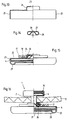
- Fig. 1 shows a partially sectioned representation inventive labeling element 1. This is molded in one piece with a shaft 2 and is cup-shaped trained so that the unit of shaft 2 and boiler 3rd results. In the embodiment shown it is the labeling element 1 around a hollow rivet element. Alternatively, of course, the shaft 2, also as Hollow shaft, in a boiler provided with an opening 3 be used.
- FIG. 2a shows a plate-shaped information carrier 4 in a basic form.
- This comprises a carrier disc 5, which has a color layer 6 which can be provided with information is arranged.
- This color layer can be used for printing Embossing or the like may be provided.
- an adhesive layer 7 above the color layer 6 arranged, which for secure attachment of the protective layer 8 is provided.
- the adhesive layer 7 and the protective layer 8 are transparent so that those on the color layer 6 or Protective layer 8 arranged information visible from the outside are. It goes without saying that any one Layer structure is possible.
- the protective layer 8 in turn wear the adhesive layer 7 in a self-adhesive manner. Farther the layers can be used for any evaluation method suitable materials.
- FIG. 3a shows a mounted marking element 1 according to one embodiment.
- the information carrier 4 used according to FIG. 2a In the boiler 3 is the information carrier 4 used according to FIG. 2a. It became a Dome-shaped plastic layer 9, for example by casting arranged. At the edge the free edge of the kettle was left behind flanged on the inside, resulting in the flanged edge 10, which holds the information carrier 4 securely in the boiler 3. On the dome-shaped plastic casting or another form of protection can be dispensed with if the information carrier in the Expansion stage according to FIG. 2b is used in the boiler 3. After inserting the information carrier 4, the Flanging edge 10 by flanging the free edge of the boiler 3 are formed, whereby the information carrier 4 in the boiler 3rd is attached.
- the resulting gap between the boiler and Information carriers can be countered with suitable means Penetration of dirt, water and the like are protected, for example with plastic.
- the top view gives the appearance according to FIG. 4.
- the Labeling element 1 shows the flanged edge seen from above 10 at the top of the boiler 3 and through the Protective layer of visible and evaluable information 11, which 4 of course only indicated by way of example will. For example, barcodes and others automatically evaluable information can be used.
- outermost edge the flanged edge 10 of the marking element 1 is.
- This for example made of metal or plastic formed element thus protects with the outside Flanged edge 10, the protective layer 8 or partially also plastic layer 9 against mechanical damage.
- Plastic layer 9 is at its thinnest and therefore weakest point protected by the flanged edge 10.
- This marking element 1 thus formed can then be used the shaft 2 through a hole in an animal or Insert item 12.
- the free one Shaft end also be designed to be self-tapping.
- FIG. 6 Another securing element is shown in FIG. 6.
- a pot-shaped Fuse element a so-called fuse pot 15.
- This has a bottom opening 16 and a cylindrical Circumferential surface 19 over a defined axial length.
- the free The end of the fuse pot 15 is again disk-like radial reshaped to the outside.
- Such a fuse box can the free shaft end arranged by widening the same be by the free shaft end from the outside through the opening 16 passed in the bottom of the fuse pot 15 and in the Pot is expanded. This arrangement can be done with or can be used without washer 13.
- the fuse box 15 is used when, as often required, Additional elements 17, as shown in Fig. 7, can be used should.
- the Labeling of animals or objects related to a transponder should be checked for their movement 18 to use. This is one on a signal towards an evaluable transmitter. So can for example the location of an animal be determined.
- the transponder 18 in a disc-shaped additional element 17 introduced which can also be a functional element, serves as an antenna, for example. It is also conceivable that To provide additional element with other functional elements.
- Fig. 8 shows the assembly unit from fuse box 15 and Additional element 17.
- Fuse pot 15 By forming the cylinder part 19 on Fuse pot 15 results in a cylindrical surface, which the tilt and movement-resistant arrangement of an additional element 17 serves.
- the outwardly shaped peripheral edge the fuse pot 15 as a stop and mounting surface serve for the additional element 17.
- This assembly unit shown in Fig. 8 can then in the Fig. 9 shown way with the labeling element 1 an identification system on an animal or Item 12 are attached.
- the one with the Additional element 17 provided fuse box with its Bottom to the animal or object to be labeled arranged.
- the shaft 2 of the labeling element 1 which in the manner described above with the Information carrier 4 is provided, penetrates the animal or the object 12 and the opening 16 in the bottom of the Safety pot 15. Then the free end of the shaft 2 expanded in the fuse pot 15 so that the expansion 14th the secure connection between the shaft 2 and the Fuse pot 15 is used.
- the identification system arranged in this way is thus safe on the animal or object 12 attached and also provided with the additional element 17. Due to the enlarged diameter of the cylinder 19 am Safety pot 15 and the large mounting surface on That fits the cylinder circumference and on the outer fastening edge Additional element against movement and tilting on the identification system.
- FIG. 10 An alternative or further developed embodiment of a The labeling element according to the invention is in FIG. 10 shown.
- this Labeling element 1 according to FIG. 10 one to the outside formed free edge. So that the cylindrical outer Circumference of the boiler 3 for receiving an additional element 17 in the manner described with regard to the fuse pot 15 to serve.
- an information carrier can still be used in the label element, for example shown in Fig. 3a or by using Circlips and the like
- FIG. 11 An alternative securing element is in the form in FIG. 11 a push button ball 20 shown.
- a push button ball 20 As seen in Fig. 12, can the push button ball 20 directly on the free end of the Shaft 2 are applied in a conventional manner.
- the Free shaft end 21 then forms in the Push button technology known way in the push button ball a.
- the animal or animal to be labeled The object is then between the bottom of the boiler Labeling element 1 and the push button ball flange added.
- the identification system is therefore safe characteristic animal or object attached.
- a labeling element as in 3a or 3b can be used.
- FIG. 13 shows a further embodiment of a Fuse 22, which is also in the above for Fuse pot 15 described embodiment to the Safety pot top molded molded boiler 25.
- a Fuse 22 which is also in the above for Fuse pot 15 described embodiment to the Safety pot top molded molded boiler 25.
- a boiler 25 outwardly deformed upper edge trained, for example, the inclusion of a Additional element or an information carrier can serve.
- a closed safety pot according to Fig. 15 or one with an additional element 17 or one Information carrier 4 provided security pot 22 according to FIG. 13 the interior of the pot is no longer accessible, the in Fig. 14 shown rapid cap proposed.
- a rapid cap 26 as shown in FIG. 14 is a component which when using non self-piercing push button or Rivet systems can be used. It enables, as in present case that when pushing through the shaft 2 by an object or animal to be labeled Counter bearing is formed. After enforcement, the Rapid cap 26 with its guide cone 28, which the shaft 2 is accessible through the opening 27 on the rapid cap 26, a Expansion counter bearing. The free shaft end is inevitably led to the expansion into the interior of the cap.
- a fuse pot 22 according to FIG. 13 is in his pot part provided with a rapid cap 26. On the cylindrical region 24 is an additional element 17 with a Transponder 28 arranged.
- a Information carrier 4 used, in the embodiment shown an information carrier 4 according to FIG. 2b.
- the free The edge of the boiler 25 is then the same as for the labeling element 1 crimped inwards so that it is the information carrier securing flanged edge 29 results.
- the opening 23 in the bottom of the Fuse 22 is in register with the opening 27 in the Rapid cap 26.
- FIG. 16 shows the exemplary arrangement of a identification system according to the invention using a labeling element 1 and a Fuse 22 in the shown in Fig. 15 Assembly unit.
- the shaft 2 of the securing element 1 which is constructed in the manner described above, penetrates a hole in the animal or object 12. This hole can due to the use of the rapid cap also during assembly of the identification system are manufactured independently.
- the free end 21 of the shaft penetrates the opening 23 at the bottom of the fuse pot 22 and at the same time the opening 27 in the Rapid cap 26 and abuts a peripheral area Guide cone 28 of the rapid cap 26. If maintained or Increasing the pressure, the free shaft end 21 is inevitable expanded inside the rapid cap 26. This Widening can go so far that the free shaft end 21 flanged once again on the shaft 2.
- this shown identification system it is possible in addition to the pure label element, which in in a particularly simple and reliable manner on the item to be labeled Animal or object 12 can be attached, additional elements 17 or to arrange further information carriers 4.
- Identification system with regard to its form of assembly and its application possibilities is not limited.
- Labeling of animals of any kind can, for example Label textiles, among other things for theft protection, for tracking or simply for illustration evaluable information for example for washing and Cleaning operations.
Landscapes
- Engineering & Computer Science (AREA)
- Theoretical Computer Science (AREA)
- Physics & Mathematics (AREA)
- General Physics & Mathematics (AREA)
- Life Sciences & Earth Sciences (AREA)
- Environmental Sciences (AREA)
- Computer Hardware Design (AREA)
- Microelectronics & Electronic Packaging (AREA)
- Zoology (AREA)
- Animal Husbandry (AREA)
- Biodiversity & Conservation Biology (AREA)
- Birds (AREA)
- Radar Systems Or Details Thereof (AREA)
- Adornments (AREA)
Description
- Fig. 1
- eine teilgeschnittene Darstellung eines erfindungsgemäßen Kennzeichnungselementes;
- Fig. 2a
- eine schematische Darstellung eines Informationsträgers gemäß einer ersten Alternative;
- Fig. 2b
- eine schematische Darstellung eines Informationsträgers gemäß einer zweiten Alternative;
- Fig. 3a
- eine teilgeschnittene Darstellung eines Kennzeichnungselementes mit Informationsträger gemäß Fig. 2a;
- Fig. 3b
- eine teilgeschnittene Darstellung eines Kennzeichnungselementes mit Informationsträger gemäß Fig. 2b;
- Fig. 4
- eine Draufsicht auf ein Kennzeichnungselement mit einer Beispielsinformation;
- Fig. 5
- eine teilgeschnittene Darstellung eines an einem Tier oder einem Gegenstand befestigten Identifikationssystems;
- Fig. 6
- eine teilgeschnittene Darstellung eines topfförmigen Sicherungselementes;
- Fig. 7
- eine teilgeschnittene Darstellung eines Zusatzelementes;
- Fig. 8
- eine teilgeschnittene Darstellung der Montageeinheit gemäß Fig. 6 und 7;
- Fig. 9
- eine teilgeschnittene Darstellung eines an einem Tier oder einem Gegenstand befestigten Identifikationssystems gemäß einer weiteren Ausführungsform;
- Fig. 10
- eine teilgeschnittene Darstellung eines erfindungsgemäßen Kennzeichnungselementes gemäß einer weiteren Ausführungsform;
- Fig. 11
- eine teilgeschnittene Darstellung einer Druckknopfkugel;
- Fig. 12
- eine teilgeschnittene Darstellung eines an einem Tier oder einem Gegenstand befestigten Identifikationssystems gemäß einer weiteren Ausführungsform;
- Fig. 13
- eine teilgeschnittene Darstellung einer weiteren Ausführungsform eines Sicherungselementes;
- Fig. 14
- eine Schnittdarstellung durch eine Rapidkappe;
- Fig. 15
- eine teilgeschnittene Darstellung einer Montageeinheit gemäß Fig. 13 und 14 und
- Fig. 16
- eine teilgeschnittene Darstellung eines an einem Tier oder einem Gegenstand befestigten Identifikationssystems gemäß einer weiteren Ausführungsform.
- 1
- Kennzeichnungselement
- 2
- Schaft
- 3
- Kessel
- 4
- Informationsträger
- 5
- Trägerscheibe
- 6
- Farbschicht
- 7
- Kleberschicht
- 8
- Schutzschicht
- 9
- Kunststoffschicht
- 10
- Bördelkante
- 11
- Information
- 12
- Tier/Gegenstand
- 13
- Unterlegscheibe
- 14
- Aufweitung
- 15
- Sicherungstopf
- 16
- Öffnung
- 17
- Zusatzelement
- 18
- Transponder
- 19
- Zylinder
- 20
- Druckknopfkugel
- 21
- freies Schaftende
- 22
- Sicherungstopf
- 23
- Öffnung
- 24
- Zylinder
- 25
- Kessel
- 26
- Rapidkappe
- 27
- Öffnung
- 28
- Führungskegel
- 29
- Bördelkante
Claims (10)
- Identifikationssystem zur Kennzeichnung von Tieren oder Gegenständen mit einem Schaft (2), der mit beiden Enden freiliegend in ein Loch in einem Tier oder einem Gegenstand (12) einsetzbar ist, einem Kennzeichnungselement (1) und einem Sicherungselement, welche jeweils an einem der freien Enden des Schaftes (2) befestigbar sind, wobei das Kennzeichnungselement (1) kesselförmig ausgebildet ist, und in dem in Befestigungslage vom Schaft (2) wegweisenden Kessel (3) ein plattenförmiger Informationsträger (4) einsetzbar und dort befestigbar ist,
dadurch gekennzeichnet,
daß das Kennzeichnungselement (1) und der Schaft (2) einstückig als Nietteil ausgebildet sind und das Sicherungselement einen Sicherungstopf (15, 22) aufweist. - Identifikationssystem nach Anspruch 1, dadurch gekennzeichnet, daß der Informationsträger (4) ein aus mehreren Schichten (5, 6, 7) aufgebautes scheibenförmiges Element ist.
- Identifikationssystem nach Anspruch 2, dadurch gekennzeichnet, daß auf dem Informationsträger (4) eine Schutzschicht (8) angeordnet ist.
- Identifikationssystem nach einem der vorhergehenden Ansprüche, dadurch gekennzeichnet daß das Kennzeichnungselement (1) an seinem freien Ende des Kessels (3) eine nach innen umgelegte Bördelkante (10) aufweist.
- Identifikationssystem nach einem der vorhergehenden Ansprüche, dadurch gekennzeichnet, daß das Sicherungselement durch eine Aufweitung (14) des freien Endes des Schaftes (2) gebildet ist.
- Identifikationssystem nach Anspruch 5, dadurch gekennzeichnet, daß auf dem Schaft (2) eine Unterlegscheibe (13) angeordnet ist.
- Identifikationssystem nach einem der vorhergehenden Ansprüche, dadurch gekennzeichnet, daß das Sicherungselement eine Druckknopfkugel ist.
- Identifikationssystem nach einem der vorhergehenden Ansprüche, dadurch gekennzeichnet, daß das Sicherungselement eine Rapidkappe (26) aufweist.
- Identifikationssystem nach einem der vorhergehenden Ansprüche, dadurch gekennzeichnet, daß im Bereich des Sicherungselementes ein Zusatzelement (17) angeordnet ist.
- Identifikationssystem nach einem der vorhergehenden Ansprüche, dadurch gekennzeichnet, daß an dem Sicherungselement ein zusätzlicher Informationsträger (4) angeordnet ist.
Applications Claiming Priority (2)
| Application Number | Priority Date | Filing Date | Title |
|---|---|---|---|
| DE4315366 | 1993-05-08 | ||
| DE4315366A DE4315366A1 (de) | 1993-05-08 | 1993-05-08 | Identifikationssystem zur Kennzeichnung von Tieren oder Gegenständen |
Publications (2)
| Publication Number | Publication Date |
|---|---|
| EP0624312A1 EP0624312A1 (de) | 1994-11-17 |
| EP0624312B1 true EP0624312B1 (de) | 1998-01-07 |
Family
ID=6487577
Family Applications (1)
| Application Number | Title | Priority Date | Filing Date |
|---|---|---|---|
| EP94106182A Expired - Lifetime EP0624312B1 (de) | 1993-05-08 | 1994-04-21 | Identifikationssystem zur Kennzeichnung von Tieren oder Gegenständen |
Country Status (3)
| Country | Link |
|---|---|
| EP (1) | EP0624312B1 (de) |
| DE (2) | DE4315366A1 (de) |
| ES (1) | ES2111792T3 (de) |
Families Citing this family (9)
| Publication number | Priority date | Publication date | Assignee | Title |
|---|---|---|---|---|
| DE29511183U1 (de) * | 1995-07-18 | 1996-11-14 | Diehl Ident Gmbh | Transponder-Ohrmarke |
| AU670907B3 (en) * | 1995-11-03 | 1996-08-01 | Alfa Laval Agri Ab | Attachable transponder housing |
| DE19747152A1 (de) * | 1997-10-24 | 1999-04-29 | Bosch Siemens Hausgeraete | Vorrichtung zur maschinenlesbaren Kennzeichnung von Textilien |
| DE19747153A1 (de) * | 1997-10-24 | 1999-04-29 | Bosch Siemens Hausgeraete | Vorrichtung zur maschinenlesbaren Kennzeichnung von Textilien |
| FR2779261B1 (fr) * | 1998-05-28 | 2003-06-13 | Reydet Finance | Element d'identification electronique et dispositif d'identification, notamment pour animaux, associes a l'element |
| GB2387468B (en) * | 2000-11-20 | 2005-01-19 | Seagate Technology Llc | RF ID Tag attachment to a disc drive |
| DE10135468A1 (de) * | 2001-07-20 | 2003-02-06 | Bsh Bosch Siemens Hausgeraete | Transponder für Textilien |
| US20050102876A1 (en) * | 2003-11-14 | 2005-05-19 | Kelly Douglas J. | Garment label |
| DE102008005363A1 (de) | 2007-04-20 | 2008-10-23 | BSH Bosch und Siemens Hausgeräte GmbH | Waschmaschine mit einer Einrichtung zum portionierten Zugeben von Waschmittelwirkstoffen |
Family Cites Families (7)
| Publication number | Priority date | Publication date | Assignee | Title |
|---|---|---|---|---|
| DE548486C (de) * | 1932-04-13 | August Ruef | Knopfverschluss fuer Briefumschlaege | |
| US1945965A (en) * | 1930-09-03 | 1934-02-06 | Marcus B Behrman | Seal |
| CH228159A (de) * | 1943-12-08 | 1943-08-15 | Ag Stoba | Ohrenplombe mit Plombierungszange. |
| NL6814283A (de) * | 1968-10-04 | 1970-04-07 | ||
| US4359015A (en) * | 1981-02-06 | 1982-11-16 | Ritchey Eugene | Identification tag for livestock |
| US4785563A (en) * | 1987-07-27 | 1988-11-22 | Otto Friedman | Animal tag microfiche indentification system |
| DE4109787A1 (de) * | 1991-03-25 | 1991-12-19 | Sietze Zijl | Traeger fuer optisch/elektronisch erkennbare mittel zur markierung eines gegenstandes |
-
1993
- 1993-05-08 DE DE4315366A patent/DE4315366A1/de not_active Withdrawn
-
1994
- 1994-04-21 DE DE59404918T patent/DE59404918D1/de not_active Expired - Fee Related
- 1994-04-21 EP EP94106182A patent/EP0624312B1/de not_active Expired - Lifetime
- 1994-04-21 ES ES94106182T patent/ES2111792T3/es not_active Expired - Lifetime
Also Published As
| Publication number | Publication date |
|---|---|
| DE4315366A1 (de) | 1994-11-10 |
| EP0624312A1 (de) | 1994-11-17 |
| DE59404918D1 (de) | 1998-02-12 |
| ES2111792T3 (es) | 1998-03-16 |
Similar Documents
| Publication | Publication Date | Title |
|---|---|---|
| DE2432444C2 (de) | Griffringsbefestigung für einen fälschungssicheren Verschluß | |
| DE69620444T2 (de) | Getränkebehälter mit interner Filter-und Anzeigevorrichtung | |
| DE29705299U1 (de) | Stempelträger | |
| EP0624312A1 (de) | Identifikationssystem zur Kennzeichnung von Tieren oder Gegenständen | |
| EP1811483A1 (de) | Verschlussplombe sowie Verfahren zu deren Herstellung | |
| DE2919023A1 (de) | Druckknopf aus kunststoff | |
| EP1618044A1 (de) | Verschlusskappe mit abdeckscheibe | |
| DE202011003520U1 (de) | Transponder-Etikett | |
| DE20104647U1 (de) | Gehäuse für eine Vorrichtung, insbesondere einen Transponder, für einen elektromagnetisch bewirkten Datenaustausch | |
| EP3798151B1 (de) | Probenflasche, insbesondere milchprobenflasche | |
| DE102010020198A1 (de) | Sicherungsmutter | |
| EP2335826A1 (de) | Indentifizierbarer Behälter | |
| DE9413608U1 (de) | Beschlag für Türen und Fenster | |
| DE102014103116B4 (de) | Etikett mit einem verdeckt darin angeordneten Code | |
| DE102018123545A1 (de) | Membran für ein Membranventil oder Stellventil mit einer Lasche und einem Transponder | |
| DE713327C (de) | Behaelterverschluss, insbesondere fuer Brennstoffbehaelter von Kraftfahrzeugen | |
| DE69406133T2 (de) | Verbesserungen an oder in bezug auf montageplatten | |
| DE9204196U1 (de) | Flaschenkasten aus Kunststoff mit eingestellten Flaschen | |
| DE2512181C3 (de) | Diebstahlsicherung für Kraftfahrzeug-Kennzeichenschilder | |
| DE3248611A1 (de) | Verschlussknopf | |
| DE20017211U1 (de) | Behälter aus Kunststoff mit einem Deckel | |
| DE3148605A1 (de) | Vorrichtung zur diebstahlsicheren befestigung eines nummernschildes an einem kraftfahrzeug | |
| DE2216132A1 (de) | Betaetigungselement fuer einen tueroder fensterverschluss | |
| DE1761268C (de) | Reiter zur Kennzeichnung von Akten, Karteikarten oder dergleichen | |
| EP3002227B1 (de) | Kunststoffbehälter mit etikettentasche |
Legal Events
| Date | Code | Title | Description |
|---|---|---|---|
| PUAI | Public reference made under article 153(3) epc to a published international application that has entered the european phase |
Free format text: ORIGINAL CODE: 0009012 |
|
| AK | Designated contracting states |
Kind code of ref document: A1 Designated state(s): DE ES FR GB NL |
|
| 17P | Request for examination filed |
Effective date: 19940920 |
|
| 17Q | First examination report despatched |
Effective date: 19960524 |
|
| RAP1 | Party data changed (applicant data changed or rights of an application transferred) |
Owner name: STOCKO FASTENERS GMBH |
|
| GRAG | Despatch of communication of intention to grant |
Free format text: ORIGINAL CODE: EPIDOS AGRA |
|
| GRAG | Despatch of communication of intention to grant |
Free format text: ORIGINAL CODE: EPIDOS AGRA |
|
| GRAH | Despatch of communication of intention to grant a patent |
Free format text: ORIGINAL CODE: EPIDOS IGRA |
|
| GRAH | Despatch of communication of intention to grant a patent |
Free format text: ORIGINAL CODE: EPIDOS IGRA |
|
| GRAA | (expected) grant |
Free format text: ORIGINAL CODE: 0009210 |
|
| AK | Designated contracting states |
Kind code of ref document: B1 Designated state(s): DE ES FR GB NL |
|
| GBT | Gb: translation of ep patent filed (gb section 77(6)(a)/1977) |
Effective date: 19980108 |
|
| REF | Corresponds to: |
Ref document number: 59404918 Country of ref document: DE Date of ref document: 19980212 |
|
| ET | Fr: translation filed | ||
| REG | Reference to a national code |
Ref country code: ES Ref legal event code: FG2A Ref document number: 2111792 Country of ref document: ES Kind code of ref document: T3 |
|
| REG | Reference to a national code |
Ref country code: FR Ref legal event code: TP |
|
| REG | Reference to a national code |
Ref country code: GB Ref legal event code: 732E |
|
| NLS | Nl: assignments of ep-patents |
Owner name: YKK CORPORATION |
|
| PLBE | No opposition filed within time limit |
Free format text: ORIGINAL CODE: 0009261 |
|
| STAA | Information on the status of an ep patent application or granted ep patent |
Free format text: STATUS: NO OPPOSITION FILED WITHIN TIME LIMIT |
|
| 26N | No opposition filed | ||
| REG | Reference to a national code |
Ref country code: ES Ref legal event code: PC2A |
|
| REG | Reference to a national code |
Ref country code: GB Ref legal event code: IF02 |
|
| PGFP | Annual fee paid to national office [announced via postgrant information from national office to epo] |
Ref country code: FR Payment date: 20080312 Year of fee payment: 15 Ref country code: ES Payment date: 20080423 Year of fee payment: 15 Ref country code: DE Payment date: 20080424 Year of fee payment: 15 |
|
| PGFP | Annual fee paid to national office [announced via postgrant information from national office to epo] |
Ref country code: NL Payment date: 20080415 Year of fee payment: 15 |
|
| PGFP | Annual fee paid to national office [announced via postgrant information from national office to epo] |
Ref country code: GB Payment date: 20080423 Year of fee payment: 15 |
|
| GBPC | Gb: european patent ceased through non-payment of renewal fee |
Effective date: 20090421 |
|
| NLV4 | Nl: lapsed or anulled due to non-payment of the annual fee |
Effective date: 20091101 |
|
| REG | Reference to a national code |
Ref country code: FR Ref legal event code: ST Effective date: 20091231 |
|
| PG25 | Lapsed in a contracting state [announced via postgrant information from national office to epo] |
Ref country code: DE Free format text: LAPSE BECAUSE OF NON-PAYMENT OF DUE FEES Effective date: 20091103 |
|
| PG25 | Lapsed in a contracting state [announced via postgrant information from national office to epo] |
Ref country code: NL Free format text: LAPSE BECAUSE OF NON-PAYMENT OF DUE FEES Effective date: 20091101 |
|
| PG25 | Lapsed in a contracting state [announced via postgrant information from national office to epo] |
Ref country code: GB Free format text: LAPSE BECAUSE OF NON-PAYMENT OF DUE FEES Effective date: 20090421 Ref country code: FR Free format text: LAPSE BECAUSE OF NON-PAYMENT OF DUE FEES Effective date: 20091222 |
|
| REG | Reference to a national code |
Ref country code: ES Ref legal event code: FD2A Effective date: 20090422 |
|
| PG25 | Lapsed in a contracting state [announced via postgrant information from national office to epo] |
Ref country code: ES Free format text: LAPSE BECAUSE OF NON-PAYMENT OF DUE FEES Effective date: 20090422 |