EP0622107A2 - Katalysator zur Reinigung von Abgasen aus Dieselmotoren - Google Patents
Katalysator zur Reinigung von Abgasen aus Dieselmotoren Download PDFInfo
- Publication number
- EP0622107A2 EP0622107A2 EP94106560A EP94106560A EP0622107A2 EP 0622107 A2 EP0622107 A2 EP 0622107A2 EP 94106560 A EP94106560 A EP 94106560A EP 94106560 A EP94106560 A EP 94106560A EP 0622107 A2 EP0622107 A2 EP 0622107A2
- Authority
- EP
- European Patent Office
- Prior art keywords
- catalyst
- loaded
- exhaust gas
- alumina
- loaded layer
- Prior art date
- Legal status (The legal status is an assumption and is not a legal conclusion. Google has not performed a legal analysis and makes no representation as to the accuracy of the status listed.)
- Granted
Links
- 239000003054 catalyst Substances 0.000 title claims abstract description 583
- KDLHZDBZIXYQEI-UHFFFAOYSA-N Palladium Chemical compound [Pd] KDLHZDBZIXYQEI-UHFFFAOYSA-N 0.000 claims abstract description 197
- BASFCYQUMIYNBI-UHFFFAOYSA-N platinum Chemical compound [Pt] BASFCYQUMIYNBI-UHFFFAOYSA-N 0.000 claims abstract description 177
- 229910052763 palladium Inorganic materials 0.000 claims abstract description 97
- 229910052697 platinum Inorganic materials 0.000 claims abstract description 86
- 238000011144 upstream manufacturing Methods 0.000 claims abstract description 66
- PNEYBMLMFCGWSK-UHFFFAOYSA-N aluminium oxide Inorganic materials [O-2].[O-2].[O-2].[Al+3].[Al+3] PNEYBMLMFCGWSK-UHFFFAOYSA-N 0.000 claims description 94
- VYPSYNLAJGMNEJ-UHFFFAOYSA-N Silicium dioxide Chemical compound O=[Si]=O VYPSYNLAJGMNEJ-UHFFFAOYSA-N 0.000 claims description 80
- GWEVSGVZZGPLCZ-UHFFFAOYSA-N Titan oxide Chemical compound O=[Ti]=O GWEVSGVZZGPLCZ-UHFFFAOYSA-N 0.000 claims description 60
- 239000010948 rhodium Substances 0.000 claims description 50
- 229910052703 rhodium Inorganic materials 0.000 claims description 49
- MHOVAHRLVXNVSD-UHFFFAOYSA-N rhodium atom Chemical group [Rh] MHOVAHRLVXNVSD-UHFFFAOYSA-N 0.000 claims description 49
- 239000000377 silicon dioxide Substances 0.000 claims description 40
- 239000000919 ceramic Substances 0.000 claims description 28
- 229910052751 metal Inorganic materials 0.000 claims description 21
- 239000002184 metal Substances 0.000 claims description 21
- 239000002245 particle Substances 0.000 claims description 11
- 229910000422 cerium(IV) oxide Inorganic materials 0.000 claims description 7
- 150000002739 metals Chemical class 0.000 claims description 7
- 239000006260 foam Substances 0.000 claims description 2
- CETPSERCERDGAM-UHFFFAOYSA-N ceric oxide Chemical compound O=[Ce]=O CETPSERCERDGAM-UHFFFAOYSA-N 0.000 claims 5
- 229910052746 lanthanum Inorganic materials 0.000 claims 3
- FZLIPJUXYLNCLC-UHFFFAOYSA-N lanthanum atom Chemical compound [La] FZLIPJUXYLNCLC-UHFFFAOYSA-N 0.000 claims 3
- 239000007789 gas Substances 0.000 description 88
- QAOWNCQODCNURD-UHFFFAOYSA-L Sulfate Chemical compound [O-]S([O-])(=O)=O QAOWNCQODCNURD-UHFFFAOYSA-L 0.000 description 35
- 230000000052 comparative effect Effects 0.000 description 30
- 239000002002 slurry Substances 0.000 description 17
- 238000012360 testing method Methods 0.000 description 17
- 239000000203 mixture Substances 0.000 description 16
- 239000000779 smoke Substances 0.000 description 14
- 238000006243 chemical reaction Methods 0.000 description 12
- 238000000746 purification Methods 0.000 description 11
- 238000001179 sorption measurement Methods 0.000 description 11
- 230000000694 effects Effects 0.000 description 10
- 230000010718 Oxidation Activity Effects 0.000 description 9
- 238000007254 oxidation reaction Methods 0.000 description 9
- 238000000034 method Methods 0.000 description 8
- 230000003247 decreasing effect Effects 0.000 description 7
- 238000000354 decomposition reaction Methods 0.000 description 6
- 230000003647 oxidation Effects 0.000 description 6
- 230000006866 deterioration Effects 0.000 description 5
- 229910052593 corundum Inorganic materials 0.000 description 4
- 238000006073 displacement reaction Methods 0.000 description 4
- 231100000572 poisoning Toxicity 0.000 description 4
- 230000000607 poisoning effect Effects 0.000 description 4
- 239000000843 powder Substances 0.000 description 4
- XLYOFNOQVPJJNP-UHFFFAOYSA-N water Chemical compound O XLYOFNOQVPJJNP-UHFFFAOYSA-N 0.000 description 4
- 229910001845 yogo sapphire Inorganic materials 0.000 description 4
- YMWUJEATGCHHMB-UHFFFAOYSA-N Dichloromethane Chemical compound ClCCl YMWUJEATGCHHMB-UHFFFAOYSA-N 0.000 description 3
- 239000007864 aqueous solution Substances 0.000 description 3
- 230000003197 catalytic effect Effects 0.000 description 3
- 239000012153 distilled water Substances 0.000 description 3
- 230000008929 regeneration Effects 0.000 description 3
- 238000011069 regeneration method Methods 0.000 description 3
- BNGXYYYYKUGPPF-UHFFFAOYSA-M (3-methylphenyl)methyl-triphenylphosphanium;chloride Chemical compound [Cl-].CC1=CC=CC(C[P+](C=2C=CC=CC=2)(C=2C=CC=CC=2)C=2C=CC=CC=2)=C1 BNGXYYYYKUGPPF-UHFFFAOYSA-M 0.000 description 2
- 230000001133 acceleration Effects 0.000 description 2
- 229910052681 coesite Inorganic materials 0.000 description 2
- 238000002485 combustion reaction Methods 0.000 description 2
- 229910052878 cordierite Inorganic materials 0.000 description 2
- 229910052906 cristobalite Inorganic materials 0.000 description 2
- JSKIRARMQDRGJZ-UHFFFAOYSA-N dimagnesium dioxido-bis[(1-oxido-3-oxo-2,4,6,8,9-pentaoxa-1,3-disila-5,7-dialuminabicyclo[3.3.1]nonan-7-yl)oxy]silane Chemical compound [Mg++].[Mg++].[O-][Si]([O-])(O[Al]1O[Al]2O[Si](=O)O[Si]([O-])(O1)O2)O[Al]1O[Al]2O[Si](=O)O[Si]([O-])(O1)O2 JSKIRARMQDRGJZ-UHFFFAOYSA-N 0.000 description 2
- 231100000614 poison Toxicity 0.000 description 2
- 235000012239 silicon dioxide Nutrition 0.000 description 2
- 229910052682 stishovite Inorganic materials 0.000 description 2
- 239000003440 toxic substance Substances 0.000 description 2
- 229910052905 tridymite Inorganic materials 0.000 description 2
- MYMOFIZGZYHOMD-UHFFFAOYSA-N Dioxygen Chemical compound O=O MYMOFIZGZYHOMD-UHFFFAOYSA-N 0.000 description 1
- 229910002060 Fe-Cr-Al alloy Inorganic materials 0.000 description 1
- 238000010521 absorption reaction Methods 0.000 description 1
- 230000032683 aging Effects 0.000 description 1
- 238000006555 catalytic reaction Methods 0.000 description 1
- 238000011161 development Methods 0.000 description 1
- 230000018109 developmental process Effects 0.000 description 1
- 238000010790 dilution Methods 0.000 description 1
- 239000012895 dilution Substances 0.000 description 1
- 229910001882 dioxygen Inorganic materials 0.000 description 1
- 238000002474 experimental method Methods 0.000 description 1
- 239000000446 fuel Substances 0.000 description 1
- 150000002500 ions Chemical class 0.000 description 1
- 238000002156 mixing Methods 0.000 description 1
- 238000012986 modification Methods 0.000 description 1
- 230000004048 modification Effects 0.000 description 1
- 150000003839 salts Chemical class 0.000 description 1
- 238000004062 sedimentation Methods 0.000 description 1
- RMAQACBXLXPBSY-UHFFFAOYSA-N silicic acid Chemical compound O[Si](O)(O)O RMAQACBXLXPBSY-UHFFFAOYSA-N 0.000 description 1
Images

Classifications
-
- B—PERFORMING OPERATIONS; TRANSPORTING
- B01—PHYSICAL OR CHEMICAL PROCESSES OR APPARATUS IN GENERAL
- B01J—CHEMICAL OR PHYSICAL PROCESSES, e.g. CATALYSIS OR COLLOID CHEMISTRY; THEIR RELEVANT APPARATUS
- B01J37/00—Processes, in general, for preparing catalysts; Processes, in general, for activation of catalysts
- B01J37/02—Impregnation, coating or precipitation
- B01J37/024—Multiple impregnation or coating
- B01J37/0244—Coatings comprising several layers
-
- B—PERFORMING OPERATIONS; TRANSPORTING
- B01—PHYSICAL OR CHEMICAL PROCESSES OR APPARATUS IN GENERAL
- B01D—SEPARATION
- B01D53/00—Separation of gases or vapours; Recovering vapours of volatile solvents from gases; Chemical or biological purification of waste gases, e.g. engine exhaust gases, smoke, fumes, flue gases, aerosols
- B01D53/34—Chemical or biological purification of waste gases
- B01D53/92—Chemical or biological purification of waste gases of engine exhaust gases
- B01D53/94—Chemical or biological purification of waste gases of engine exhaust gases by catalytic processes
- B01D53/944—Simultaneously removing carbon monoxide, hydrocarbons or carbon making use of oxidation catalysts
-
- B—PERFORMING OPERATIONS; TRANSPORTING
- B01—PHYSICAL OR CHEMICAL PROCESSES OR APPARATUS IN GENERAL
- B01J—CHEMICAL OR PHYSICAL PROCESSES, e.g. CATALYSIS OR COLLOID CHEMISTRY; THEIR RELEVANT APPARATUS
- B01J23/00—Catalysts comprising metals or metal oxides or hydroxides, not provided for in group B01J21/00
- B01J23/38—Catalysts comprising metals or metal oxides or hydroxides, not provided for in group B01J21/00 of noble metals
- B01J23/40—Catalysts comprising metals or metal oxides or hydroxides, not provided for in group B01J21/00 of noble metals of the platinum group metals
- B01J23/44—Palladium
-
- B—PERFORMING OPERATIONS; TRANSPORTING
- B01—PHYSICAL OR CHEMICAL PROCESSES OR APPARATUS IN GENERAL
- B01J—CHEMICAL OR PHYSICAL PROCESSES, e.g. CATALYSIS OR COLLOID CHEMISTRY; THEIR RELEVANT APPARATUS
- B01J35/00—Catalysts, in general, characterised by their form or physical properties
- B01J35/19—Catalysts containing parts with different compositions
-
- F—MECHANICAL ENGINEERING; LIGHTING; HEATING; WEAPONS; BLASTING
- F02—COMBUSTION ENGINES; HOT-GAS OR COMBUSTION-PRODUCT ENGINE PLANTS
- F02B—INTERNAL-COMBUSTION PISTON ENGINES; COMBUSTION ENGINES IN GENERAL
- F02B3/00—Engines characterised by air compression and subsequent fuel addition
- F02B3/06—Engines characterised by air compression and subsequent fuel addition with compression ignition
Definitions
- the present invention relates to an exhaust gas purifying catalyst for burning and purifying HC, CO and Soluble Organic Fraction (SOF) contained in exhaust gases exhausted from diesel engines (DE), and for decreasing emission amount of diesel particulate and sulfate.
- DE diesel engines
- open-type SOF decomposition catalyst is the catalyst in which oxidation catalysts such as metals of the platinum group are loaded on the catalyst loaded layer such as activated alumina, so that not only CO and HC but also SOF in diesel particulate is oxidized, decomposed and purified.
- the open-type SOF decomposition catalyst has the disadvantage that the rejection ratio of dry suits is low. However, it is possible to reduce the amount of dry suits due to improvement of DE and fuel, and the regeneration treatment apparatus is unnecessary. Therefore, it is expected that the open-type SOF decomposition catalyst is further improved.
- the activated alumina layer formed in the open-type SOF decomposition catalyst has the characteristics for adsorbing SO2 so that SO2 in exhaust gases in DE is adsorbed into the activated alumina layer.
- the adsorbed SO2 is oxidized by catalytic action of catalyst metals, or SO2 in exhaust gases is directly oxidized.
- SO2 is emitted as SO3, and the particulate amount is increased. This is why SO2 is not measured as particulate, and SO3 is measured as particulate.
- DE enough amount of oxygen gas is contained in exhaust gases so that oxidation reaction of SO2 is generated. Then, SO3 easily reacts with much amount of aqueous vapor which are contained in exhaust gases to form sulfate.
- An object of the present invention is to provide an exhaust gas purifying catalyst for preventing particulate and sulfate from being emitted, and for effectively burning and removing HC and SOF.
- An exhaust gas purifying catalyst in DE comprising a support base, a catalyst loaded layer which is formed on the surface of the support base, and a catalyst metal which is loaded on the catalyst loaded layer is characterized in that platinum catalyst is loaded on the upstream side of an exhaust gas flow, and palladium catalyst is loaded on the lower stream side of the exhaust gas flow.
- Platinum catalyst shows excellent low temperature activity and excellent purification performance at the time of start of low velocity moving.
- oxidation of SO2 is generated at low temperature, and sulfate is actively generated at the temperature of not less than 300°C.
- palladium catalyst shows poor purification performance at low temperature, but shows excellent purification performance at high temperature.
- SO2 is oxidized by palladium catalyst at the temperature of not less than 450°C. When SO2 is oxidized by platinum catalyst, the temperature is lower than the above temperature.
- platinum catalyst is loaded on the upstream side, and palladium catalyst is loaded on the lower stream side. Therefore, when the temperature of exhaust gases is not more than 300°C, platinum catalyst at the upstream side purifies HC and SOF, and no oxidation of SO2 is generated.
- the lower stream side of the support base has higher temperature than that of the upstream side of the support base due to reaction heat of catalytic reaction.
- platinum catalyst is also loaded on the lower stream side, oxidation of SO2 is generated, and sulfate is generated at early stages.
- palladium catalyst instead of platinum catalyst is loaded on the lower stream side, sulfate is not generated until the temperature rises to not less than 450°C. Therefore, sulfate is prevented from being emitted at low temperature.
- the ratio of the volume of platinum loaded portion at the upstream side to the volume of palladium loaded portion at the lower stream side is desirably in the range of 1:10 to 5:10.
- the ratio of the volume of platinum loaded portion at the upstream side is more than 5, generation amount of sulfate is increased.
- the ratio of the volume of platinum loaded portion at the upstream side is less than 1, oxidation activity is deteriorated.
- Ceramic monolith support, ceramic foam support or metal honeycomb support is used as a support base.
- Alumina, silica or titania is used as a catalyst loaded layer.
- Silica or titania is especially used as the catalyst loaded layer at the lower stream side on which palladium catalyst is loaded. Since silica or titania doesn't adsorb SO2, sulfate is prevented from generating. Silica or titania prevents catalyst metals from poisoning deterioration since silica or titania doesn't have disadvantages that palladium catalyst is covered and activity is deteriorated.
- the mixing ratio of silica and alumina is desirably in the range of 9:1 to 1:1 by weight ratio.
- the ratio of alumina is more than 1, poisoning deterioration of palladium catalyst caused by adsorption of sulfate is increased.
- the ratio of silica is more than 9, oxidation activity is deteriorated.
- the diameter of particles is in the range of 0.1 to 10 ⁇ m, preferably 10.5 to 5 ⁇ m.
- An exhaust gas purifying catalyst in DE according to the second invention is characterized in that platinum catalyst is further loaded on the lowest stream side of the exhaust gas flow.
- HC and SOF in the incomplete combustion condition which are exhausted from palladium loaded portion are burned and oxidized by platinum catalyst which is loaded on the lowest stream side of the exhaust gas flow, thereby preventing white smoke from being emitted.
- the loaded amount of platinum catalyst is desirably in the minimum range in which HC and SOF can be burned and removed.
- catalyst metals except platinum and palladium can be used with platinum and palladium.
- the exhaust gas purifying catalyst in the present invention When the exhaust gas purifying catalyst in the present invention is used, it is contacted to exhaust gases at the upstream edge portion. SOF is likely to be adsorbed to this portion, but HC and SOF are burned and removed by platinum catalyst which is loaded on this portion and which is excellent in low temperature activity, thereby preventing sedimentation of HC and SOF. Therefore, temporary poisoning due to HC and SOF is prevented at the upstream edge portion and catalyst activity is not deteriorated.
- Palladium catalyst in which oxidation reaction of SO2 generates at higher temperature than that of platinum catalyst is loaded on the portion leading to the upstream edge portion. So, SO2 is emitted at low temperature without being oxidized, and particulate and sulfate are prevented from being emitted as compared with conventional exhaust gas purifying catalyst.
- Palladium catalyst shows small activity against HC and SOF at low temperature, and HC and SOF which are not removed by the catalyst loaded layer at palladium catalyst loaded portion is likely to be adsorbed. So, when exhaust gas having high temperature and high gas flow velocity flows, adsorbed HC and SOF are eliminated to generate white smoke. Therefore, when platinum catalyst is loaded on the lowest stream side which is lower than the palladium catalyst loaded portion, eliminated HC and SOF are burned and removed by the platinum catalyst, thereby preventing them from being emitted. As a result, white smoke is prevented from being generated.
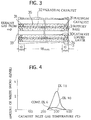
- Figures 1 and 2 are schematic vertical cross-sectional views for showing the exhaust gas purifying catalyst for diesel engines according to the present invention.
- the exhaust gas purifying catalyst comprised a first catalyst 1 and a second catalyst 2. These catalysts were arranged in a case 100 in such a manner that they were parallel and in series with respect to the exhaust gas flow.
- the first catalyst 1 was arranged at the upstream side, and the second catalyst 2 was arranged at the lower stream side.
- the first catalyst 1 which was arranged at the upstream side of the exhaust gas flow comprised a support base 10 comprising honeycomb-shaped support made of ceramic (cordierite), a first catalyst loaded layer 11 comprising titania coated on the surface of the support base 10, palladium catalyst 12 and rhodium catalyst 13 loaded on the first catalyst loaded layer 11, a second catalyst loaded layer 14 comprising alumina ( ⁇ -alumina) coated on the surface of the first catalyst loaded layer 11, platinum catalyst 15 loaded on the second catalyst loaded layer 14.
- the second catalyst 2 which was arranged at the downstream side of the exhaust gas flow comprised a support base 20 comprising honeycomb-shaped support made of ceramic (cordierite), a third catalyst loaded layer 21 comprising titania coated on the surface of the support base 20, palladium catalyst 22 and rhodium catalyst 23 loaded on the third catalyst loaded layer 21.
- the amount of the second catalyst loaded layer 14 which was loaded on the utmost surface of the first catalyst 1 was 100g/liter. And 1.5g/liter of platinum catalyst 15 was loaded on the second catalyst loaded layer 14.
- the amount of the third catalyst loaded layer 21 which was loaded on the utmost surface of the second catalyst 2 was 100g/liter. 1.0g/liter of the palladium catalyst 22 and 0.1g/liter of the rhodium catalyst 23 were loaded on the third catalyst loaded layer 21.
- a ratio of the volume of the first catalyst 1 to the volume of the second catalyst 2 was 1:5.
- the exhaust gas purifying catalyst for DE in the Example 1 was installed into exhaust system of DE (air volume displacement being 3.6 liters) with natural air intake type accessory cell to perform a purifying test.
- the first catalyst 1 was arranged at the upstream side of exhaust gas flow, and the second catalyst 2 was arranged at the downstream side. Then, these catalysts were subjected to aging by full load with the rotating speed of 2100rpm for 100 hours. After that, the catalysts were operated under the condition that the rotating speed was 2100rpm and the torque was 87Nm, and particulates were analyzed at gas temperature of 360°C.
- the analysis was performed about the amount of particulates, the SOF amount and the sulfate amount.
- a dilution tunnel corresponding to EPA was used for trapping particulates.
- SOF was extracted by Soxhlet extractor by means of dichloromethane.
- the amount of sulfate was analyzed by ion chromatograph. The result was shown in Table 2.
- the first catalyst 1 which was arranged at the upstream side of the exhaust gas flow comprised a support base 10 comprising honeycomb-shaped support made of ceramic, a first catalyst loaded layer 11 comprising titania coated on the surface of the support base 10, palladium catalyst 12 and rhodium catalyst 13 loaded on the first catalyst loaded layer 11, a second catalyst loaded layer 14 comprising aluminalanthanum coated on the surface of the first catalyst loaded layer 11, platinum catalyst 15 loaded on the second catalyst loaded layer 14.
- the second catalyst 2 which was arranged at the downstream side of the exhaust gas flow comprised a support base 20 comprising honeycomb-shaped support made of ceramic, a third catalyst loaded layer 21 comprising silica-titania coated on the surface of the support base 20, palladium catalyst 22 and rhodium catalyst 23 loaded on the third catalyst loaded layer 21.
- the amount of the second catalyst loaded layer 14 which was loaded on the utmost surface of the first catalyst 1 was 120g/liter. 1.5g/liter of the platinum catalyst 15 was loaded on the second catalyst loaded layer 14.
- the amount of the third catalyst loaded layer 21 which was loaded on the utmost surface of the second catalyst 2 was 120g/liter. 1.0g/liter of the palladium catalyst 22 and 0.1g/liter of the rhodium catalyst 23 were loaded on the third catalyst loaded layer 21.
- a ratio of the volume of the first catalyst 1 to the volume of the second catalyst 2 was 1:5.
- the first catalyst 1 which was arranged at the upstream side of the exhaust gas flow comprised a support base 10 comprising honeycomb-shaped support made of ceramic, a first catalyst loaded layer 11 comprising titania coated on the surface of the support base 10, palladium catalyst 12 and rhodium catalyst 13 loaded on the first catalyst loaded layer 11, a second catalyst loaded layer 14 comprising alumina-ceria coated on the surface of the first catalyst loaded layer 11, platinum catalyst 15 loaded on the second catalyst loaded layer 14.
- the second catalyst 2 which was arranged at the downstream side of the exhaust gas flow comprised a support base 20 comprising honeycomb-shaped support made of ceramic, a third catalyst loaded layer 21 comprising silica-alumina coated on the surface of the support base 20, palladium catalyst 22 and rhodium catalyst 23 loaded on the third catalyst loaded layer 21.
- the amount of the second catalyst loaded layer 14 which was loaded on the utmost surface of the first catalyst 1 was 100g/liter. 1.2g/liter of the platinum catalyst 15 was loaded on the second catalyst loaded layer 14.
- the amount of the third catalyst loaded layer 21 which was loaded on the utmost surface of the second catalyst 2 was 100g/liter. 1.06/liter of the palladium catalyst 22 and 0.1g/liter of the rhodium catalyst 23 were loaded on the third catalyst loaded layer 21.
- a ratio of the volume of the first catalyst 1 to the volume of the second catalyst 2 was 1:10.
- the first catalyst 1 which was arranged at the upstream side of the exhaust gas flow comprised a support base 10 comprising honeycomb-shaped support made of metal, a first catalyst loaded layer 11 comprising titania coated on the surface of the support base 10, palladium catalyst 12 and rhodium catalyst 13 loaded on the first catalyst loaded layer 11, a second catalyst loaded layer 14 comprising alumina coated on the surface of the first catalyst loaded layer 11, platinum catalyst 15 loaded on the second catalyst loaded layer 14.
- the second catalyst 2 which was arranged at the downstream side of the exhaust gas flow comprised a support base 20 comprising honeycomb-shaped support made of metal, a third catalyst loaded layer 21 comprising alumina coated on the surface of the support base 20, palladium catalyst 22 and rhodium catalyst 23 loaded on the third catalyst loaded layer 21.
- the amount of the second catalyst loaded layer 14 which was loaded on the utmost surface of the first catalyst 1 was 100g/liter. 1.2g/liter of the platinum catalyst 15 was loaded on the second catalyst loaded layer 14.
- the amount of the third catalyst loaded layer 21 which was loaded on the utmost surface of the second catalyst 2 was 100g/liter. 1.0g/liter of the palladium catalyst 22 and 0.1g/liter of the rhodium catalyst 23 were loaded on the third catalyst loaded layer 21.
- a ratio of the volume of the first catalyst 1 to the volume of the second catalyst 2 was 1:10.
- the first catalyst 1 which was arranged at the upstream side of the exhaust gas flow comprised a support base 10 comprising honeycomb-shaped support made of ceramic, a first catalyst loaded layer 11 comprising titania coated on the surface of the support base 10, palladium catalyst 12 and rhodium catalyst 13 loaded on the first catalyst loaded layer 11, a second catalyst loaded layer 14 comprising alumina coated on the surface of the first catalyst loaded layer 11, platinum catalyst 15 and rhodium catalyst loaded on the second catalyst loaded layer 14.
- the second catalyst 2 which was arranged at the downstream side of the exhaust gas flow comprised a support base 20 comprising honeycomb-shaped support made of ceramic, a third catalyst loaded layer 21 comprising alumina-ceria coated on the surface of the support base 20, palladium catalyst 22 and rhodium catalyst 23 loaded on the third catalyst loaded layer 21.
- the amount of the second catalyst loaded layer 14 which was loaded on the utmost surface of the first catalyst 1 was 100g/liter. 1.2g/liter of the platinum catalyst 15 and 0.2g/liter of the rhodium catalyst were loaded on the second catalyst loaded layer 14.
- the amount of the third catalyst loaded layer 21 which was loaded on the utmost surface of the second catalyst 2 was 100g/liter. 1.2g/liter of the palladium catalyst 22 and 0.2g/liter of the rhodium catalyst 23 were loaded on the third catalyst loaded layer 21.
- a ratio of the volume of the first catalyst 1 to the volume of the second catalyst 2 was 3:10.
- the first catalyst 1 which was arranged at the upstream side of the exhaust gas flow comprised a support base 10 comprising honeycomb-shaped support made of ceramic, a first catalyst loaded layer 11 comprising titania coated on the surface of the support base 10, palladium catalyst 12 and rhodium catalyst 13 loaded on the first catalyst loaded layer 11, a second catalyst loaded layer 14 comprising titania coated on the surface of the first catalyst loaded layer 11, platinum catalyst 15 and rhodium catalyst loaded on the second catalyst loaded layer 14.
- the second catalyst 2 which was arranged at the downstream side of the exhaust gas flow comprised a support base 20 comprising honeycomb-shaped support made of ceramic, a third catalyst loaded layer 21 comprising alumina coated on the surface of the support base 20, palladium catalyst 22 and rhodium catalyst 23 loaded on the third catalyst loaded layer 21.
- the amount of the second catalyst loaded layer 14 which was loaded on the utmost surface of the first catalyst 1 was 100g/liter. 1.2g/liter of the platinum catalyst 15 and 0.2g/liter of the rhodium catalyst were loaded on the second catalyst loaded layer 14.
- the amount of the third catalyst loaded layer 21 which was loaded on the utmost surface of the second catalyst 2 was 100g/liter. 1.2g/liter of the palladium catalyst 22 and 0.2g/liter of the rhodium catalyst 23 were loaded on the third catalyst loaded layer 21.
- a ratio of the volume of the first catalyst 1 to the volume of the second catalyst 2 was 3:10.
- the first catalyst 1 which was arranged at the upstream side of the exhaust gas flow comprised a support base 10 comprising honeycomb-shaped support made of ceramic, a first catalyst loaded layer 11 comprising titania coated on the surface of the support base 10, palladium catalyst 12 and rhodium catalyst 13 loaded on the first catalyst loaded layer 11, a second catalyst loaded layer 14 comprising silica coated on the surface of the first catalyst loaded layer 11, platinum catalyst 15 and rhodium catalyst loaded on the second catalyst loaded layer 14.
- the second catalyst 2 which was arranged at the downstream side of the exhaust gas flow comprised a support base 20 comprising honeycomb-shaped support made of ceramic, a third catalyst loaded layer 21 comprising silica coated on the surface of the support base 20, palladium catalyst 22 and rhodium catalyst 23 loaded on the third catalyst loaded layer 21.
- the amount of the second catalyst loaded layer 14 which was loaded on the utmost surface of the first catalyst 1 was 100g/liter. 1.2g/liter of the platinum catalyst 15 and 0.2g/liter of the rhodium catalyst were loaded on the second catalyst loaded layer 14.
- the amount of the third catalyst loaded layer 21 which was loaded on the utmost surface of the second catalyst 2 was 100g/liter. 1.2g/liter of the palladium catalyst 22 and 0.2g/liter of the rhodium catalyst 23 were loaded on the third catalyst loaded layer 21.
- a ratio of the volume of the first catalyst 1 to the volume of the second catalyst 2 was 1:5.
- the first catalyst 1 which was arranged at the upstream side of the exhaust gas flow comprised a support base 10 comprising honeycomb-shaped support made of ceramic, a first catalyst loaded layer 11 comprising titania coated on the surface of the support base 10, palladium catalyst 12 and rhodium catalyst 13 loaded on the first catalyst loaded layer 11, a second catalyst loaded layer 14 comprising alumina coated on the surface of the first catalyst loaded layer 11, platinum catalyst 15 loaded on the second catalyst loaded layer 14.
- the second catalyst 2 which was arranged at the downstream side of the exhaust gas flow comprised a support base 20 comprising honeycomb-shaped support made of ceramic, a third catalyst loaded layer 21 comprising silica-titania coated on the surface of the support base 20, palladium catalyst 22 loaded on the third catalyst loaded layer 21.
- the amount of the second catalyst loaded layer 14 which was loaded on the utmost surface of the first catalyst 1 was 100g/liter. 1.2g/liter of the platinum catalyst 15 was loaded on the second catalyst loaded layer 14.
- the amount of the third catalyst loaded layer 21 which was loaded on the utmost surface of the second catalyst 2 was 100g/liter. 1.0g/liter of the palladium catalyst 22 was loaded on the third catalyst loaded layer 21.
- a ratio of the volume of the first catalyst 1 to the volume of the second catalyst 2 was 1:5.
- the first catalyst 1 which was arranged at the upstream side of the exhaust gas flow comprised a support base 10 comprising honeycomb-shaped support made of ceramic, a first catalyst loaded layer 11 comprising titania coated on the surface of the support base 10, palladium catalyst 12 and rhodium catalyst 13 loaded on the first catalyst loaded layer 11, a second catalyst loaded layer 14 comprising alumina coated on the surface of the first catalyst loaded layer 11, platinum catalyst 15 loaded on the second catalyst loaded layer 14.
- the second catalyst 2 which was arranged at the downstream side of the exhaust gas flow comprised a support base 20 comprising honeycomb-shaped support made of ceramic, a third catalyst loaded layer 21 comprising alumina coated on the surface of the support base 20, palladium catalyst 22 loaded on the third catalyst loaded layer 21.
- the amount of the second catalyst loaded layer 14 which was loaded on the utmost surface of the first catalyst 1 was 100g/liter. 1.2g/liter of the platinum catalyst 15 was loaded on the second catalyst loaded layer 14.
- the amount of the third catalyst loaded layer 21 which was loaded on the utmost surface of the second catalyst 2 was 100g/liter. 1.0g/liter of the palladium catalyst 22 was loaded on the third catalyst loaded layer 21.
- a ratio of the volume of the first catalyst 1 to the volume of the second catalyst 2 was 1:5.
- a Comparative Example 1 was performed as follows.
- the first catalyst 1 which was arranged at the upstream side of the exhaust gas flow comprised a support base 10 comprising honeycomb-shaped support made of ceramic, a first catalyst loaded layer 11 comprising titania coated on the surface of the support base 10, palladium catalyst 12 and rhodium catalyst 13 loaded on the first catalyst loaded layer 11, a second catalyst loaded layer 14 comprising alumina coated on the surface of the first catalyst loaded layer 11, platinum catalyst 15 loaded on the second catalyst loaded layer 14.
- the second catalyst 2 which was arranged at the downstream side of the exhaust gas flow comprised a support base 20 comprising honeycomb-shaped support made of ceramic, a third catalyst loaded layer 21 comprising alumina coated on the surface of the support base 20, platinum catalyst loaded on the third catalyst loaded layer 21.
- the amount of the second catalyst loaded layer 14 which was loaded on the utmost surface of the first catalyst 1 was 100g/liter. 1.5g/liter of the platinum catalyst 15 was loaded on the second catalyst loaded layer 14.
- the amount of the third catalyst loaded layer 21 which was loaded on the utmost surface of the second catalyst 2 was 100g/liter. 1.5g/liter of the platinum catalyst was loaded on the third catalyst loaded layer 21.
- a Comparative Example 2 was performed as follows.
- the first catalyst 1 which was arranged at the upstream side of the exhaust gas flow comprised a support base 10 comprising honeycomb-shaped support made of ceramic, a first catalyst loaded layer 11 comprising titania coated on the surface of the support base 10, palladium catalyst 12 and rhodium catalyst 13 loaded on the first catalyst loaded layer 11, a second catalyst loaded layer 14 comprising alumina coated on the surface of the first catalyst loaded layer 11, palladium catalyst loaded on the second catalyst loaded layer 14.
- the second catalyst 2 which was arranged at the downstream side of the exhaust gas flow comprised a support base 20 comprising honeycomb-shaped support made of ceramic, a third catalyst loaded layer 21 comprising alumina coated on the surface of the support base 20, palladium catalyst 22 loaded on the third catalyst loaded layer 21.
- the amount of the second catalyst loaded layer 14 which was loaded on the utmost surface of the first catalyst 1 was 100g/liter. 1.5g/liter of the palladium catalyst was loaded on the second catalyst loaded layer 14.
- the amount of the third catalyst loaded layer 21 which was loaded on the utmost surface of the second catalyst 2 was 100g/liter. 1.5g/liter of the palladium catalyst 22 was loaded on the third catalyst loaded layer 21.
- a Comparative Example 3 was performed as follows.
- the first catalyst 1 which was arranged at the upstream side of the exhaust gas flow comprised a support base 10 comprising honeycomb-shaped support made of metal, a first catalyst loaded layer 11 comprising titania coated on the surface of the support base 10, palladium catalyst 12 and rhodium catalyst 13 loaded on the first catalyst loaded layer 11, a second catalyst loaded layer 14 comprising alumina coated on the surface of the first catalyst loaded layer 11, platinum catalyst 15 and rhodium catalyst loaded on the second catalyst loaded layer 14.
- the second catalyst 2 which was arranged at the downstream side of the exhaust gas flow comprised a support base 20 comprising honeycomb-shaped support made of metal, a third catalyst loaded layer 21 comprising alumina coated on the surface of the support base 20, platinum catalyst and rhodium catalyst 23 loaded on the third catalyst loaded layer 21.
- the amount of the second catalyst loaded layer 14 which was loaded on the utmost surface of the first catalyst 1 was 100g/liter. 1.2g/liter of the platinum catalyst 15 and 0.2g/liter of the rhodium catalyst were loaded on the second catalyst loaded layer 14.
- the amount of the third catalyst loaded layer 21 which was loaded on the utmost surface of the second catalyst 2 was 100g/liter. 1.2g/liter of the platinum catalyst and 0.2g/liter of the rhodium catalyst 23 were loaded on the third catalyst loaded layer 21.
- a Comparative Example 4 was performed as follows.
- the first catalyst 1 which was arranged at the upstream side of the exhaust gas flow comprised a support base 10 comprising honeycomb-shaped support made of ceramic, a first catalyst loaded layer 11 comprising titania coated on the surface of the support base 10, palladium catalyst 12 and rhodium catalyst 13 loaded on the first catalyst loaded layer 11, a second catalyst loaded layer 14 comprising alumina coated on the surface of the first catalyst loaded layer 11, palladium catalyst and rhodium catalyst loaded on the second catalyst loaded layer 14.
- the second catalyst 2 which was arranged at the downstream side of the exhaust gas flow comprised a support base 20 comprising honeycomb-shaped support made of ceramic, a third catalyst loaded layer 21 comprising alumina coated on the surface of the support base 20, palladium catalyst 22 and rhodium catalyst 23 loaded on the third catalyst loaded layer 21.
- the amount of the second catalyst loaded layer 14 which was loaded on the utmost surface of the first catalyst 1 was 100g/liter. 1.2g/liter of the palladium catalyst and 0.2g/liter of the rhodium catalyst were loaded on the second catalyst loaded layer 14.
- the amount of the third catalyst loaded layer 21 which was loaded on the utmost surface of the second catalyst 2 was 100g/liter. 1.2g/liter of the palladium catalyst 22 and 0.2g/liter of the rhodium catalyst 23 were loaded on the third catalyst loaded layer 21.
- a Comparative Example 5 was performed as follows.
- the first catalyst 1 which was arranged at the upstream side of the exhaust gas flow comprised a support base 10 comprising honeycomb-shaped support made of ceramic, a first catalyst loaded layer 11 comprising titania coated on the surface of the support base 10, palladium catalyst 12 and rhodium catalyst 13 loaded on the first catalyst loaded layer 11, a second catalyst loaded layer 14 comprising alumina coated on the surface of the first catalyst loaded layer 11, platinum catalyst 15 and palladium catalyst loaded on the second catalyst loaded layer 14.
- the second catalyst 2 which was arranged at the downstream side of the exhaust gas flow comprised a support base 20 comprising honeycomb-shaped support made of ceramic, a third catalyst loaded layer 21 comprising alumina coated on the surface of the support base 20, platinum catalyst and palladium catalyst 22 loaded on the third catalyst loaded layer 21.
- the amount of the second catalyst loaded layer 14 which was loaded on the utmost surface of the first catalyst 1 was 100g/liter.
- 1.0g/liter of the platinum catalyst 15 and 1.0g/liter of the palladium catalyst were loaded on the second catalyst loaded layer 14.
- the amount of the third catalyst loaded layer 21 which was loaded on the utmost surface of the second catalyst 2 was 100g/liter. 1.0g/liter of the platinum catalyst and 1.0g/liter of the palladium catalyst 22 were loaded on the third catalyst loaded layer 21.
- the present invention cannot be limited to this type.
- platinum is loaded on the upstream side in the honeycomb body and palladium is loaded on the downstream side in the honeycomb body, the same effect as above is obtained.
- the first catalyst loaded layer 11 and the second catalyst loaded layer 14 are formed on the first catalyst 1.
- the second catalyst loaded layer 14 on which the platinum catalyst is loaded is used, the same effect as above is obtained.
- the catalyst comprises a support base 3 comprising a metal support, a catalyst loaded layer 30 made of ⁇ -alumina which is covered with the surface of the support base 3, a platinum catalyst 31 and a palladium catalyst 32 which are loaded on the catalyst loaded layer 30.
- the support base 3 comprises a metal support having the diameter of 112mm and the length of 118mm forming a plane plate and a corrugated plate having the thickness of 50 ⁇ m made of Fe-Cr-Al alloy.
- 1.5g/liter of the platinum catalyst 31 was loaded on the upstream side of the support base 3 within 10mm from an upstream side edge surface 33 to a downward direction. Furthermore, 1.5g/liter of the platinum catalyst 31 was also loaded on the downstream side of the support base 3 within 10mm from a downstream side edge surface 34 to an upward direction.
- Example 11 employed the same compositions and the same manner as described in the Example 10 except that 1.5g/liter of the platinum catalyst 31 was loaded on the upstream side of the support base 3 within 10mm from an upstream side edge surface 33 to a downward direction, and that 1.8g/liter of the palladium catalyst 32 was loaded on a rest portion having the length of 108mm.
- a Comparative Example 6 employed the same compositions and the same manner as described in the Example 10 except that 1.5g/liter of the platinum catalyst 31 was loaded on the whole portion of the support base 3.
- each catalyst was installed into an exhaust system of a swirl chamber type DE having air volume displacement of 2400cc.
- a conversion ratio of SO2 to SO3 was measured by a nondispersive infrared analyzer under the condition that an exhaust gas temperature was 500°C to be represented by the following formula. The result was shown in Table 3.
- SO3 conversion ratio (inlet gas SO2 density - outlet gas SO3 density) x 100/inlet gas SO2 density TABLE 3
- Example 10 Example 11 Comparative Example 12 Upstream Side Edge Portion Pt Pt Pt Central Portion Pd Pd Pt Downstream Side Edge Portion Pt Pd Pt Conversion Ratio (%) 40 40 90
- Each catalyst was installed into an exhaust system of a swirl chamber type DE having air volume displacement of 2400cc, and was maintained in an idling condition (the temperature of the exhaust gas being 120°C) for 6 hours. After that, a rotating speed is increased and the temperature of the exhaust gas is increased to measure the amount of white smoke which is exhausted from the exhaust pipe. The result was shown in Figure 4. This experiment was performed in the condition that the temperature of the exhaust gas was variously changed. The amount of white smoke was measured by a translucent white smoke meter.
- ⁇ -alumina was used as the catalyst loaded layer of the palladium catalyst.
- a mixed layer of silica and alumina was used as the catalyst loaded layer, sulfate was not discharged.
- ⁇ -alumina was used as the catalyst loaded layer and the banadium catalyst was added to the catalyst metal, sulfate was not discharged.
- silica powder having the specific surface of 350m2/g, aluminum nitrate aqueous solution, alumina sol and distilled water were mixed to prepare a slurry A.
- alumina powder having the specific surface of 180m2/g and the particle diameter of 1 to 50 m, alumina hydrate, aluminum nitrate aqueous solution and distilled water were mixed to prepare a slurry B.
- silica powder having the specific surface of 350m2/g, silica sol and distilled water were mixed to prepare a slurry C.
- An available honeycomb support being ⁇ 30 x 50 and 400cell/in2 was subjected to water absorption treatment and was immersed into the slurry A. After an extra slurry was blown off by an air, the immersed support was dried and calcined to obtain a mixed catalyst loaded layer comprising silica and alumina.
- the coated amount was about 100g against 1 liter of the volume of the support.
- the weight ratio of silica to alumina was 9:1, and the particle diameter of alumina was not more than 5 ⁇ m.
- the coated support was immersed into ammine salt aqueous solution of palladium and rhodium, and adsorbed and loaded for a predetermined time to be dried at the temperature of 250°C.
- the loaded amount of palladium was 1.5g against 1 liter of the volume of the support.
- the loaded amount of rhodium was 0.3g against 1 liter of the volume of the support.
- the predetermined amount of platinum dinitro diammine was added to the slurry B to prepare the slurry D. Only the upstream side edge portion of the coated support was immersed into the slurry D. After an extra slurry was blown off by an air, the immersed support was dried and calcined to obtain a catalyst loaded layer comprising alumina on which platinum was loaded.
- an upstream portion comprising Pt/Al2O3 was formed on the surface of the upstream side edge portion, and a downstream portion comprising Pd-Rh/SiO2 ⁇ Al2O3 was formed on the surface of the downstream side edge portion.
- the ratio of the volume of the upstream portion to the volume of the downstream portion was 1:10.
- the loaded amount of platinum on the upstream portion was 1.5g against 1 liter of the volume of the support.
- Example 13 employed the same compositions and the same manner as described in the Example 12 except that the ratio of the volume of the upstream portion to the volume of the downstream portion was 3:10. The result was shown in Table 4.
- Example 14 employed the same compositions and the same manner as described in the Example 12 except that the ratio of the volume of the upstream portion to the volume of the downstream portion was 5:10. The result was shown in Table 4.
- Example 15 employed the same compositions and the same manner as described in the Example 12 except that the ratio of the volume of the upstream portion to the volume of the downstream portion was 0.5:10. The result was shown in Table 4.
- Example 16 employed the same compositions and the same manner as described in the Example 12 except that the ratio of the volume of the upstream portion to the volume of the downstream portion was 1:1. The result was shown in Table 4.
- Example 17 employed the same compositions and the same manner as described in the Example 12 except that the slurry A contained more amount of alumina sol. Concerning the obtained catalyst, the weight ratio of silica to alumina contained in the downstream portion was 7:3, and the ratio of the volume of the upstream portion to the volume of the downstream portion was 3:10. The result was shown in Table 4.
- Example 18 employed the same compositions and the same manner as described in the Example 17 except that the weight ratio of silica to alumina was 1:1. The result was shown in Table 4.
- Example 19 employed the same compositions and the same manner as described in the Example 17 except that the weight ratio of silica to alumina was 3:7. The result was shown in Table 4.
- Example 20 employed the same compositions and the same manner as described in the Example 17 except that the ratio of the volume of the upstream portion to the volume of the downstream portion was 9.5:0.5. The result was shown in Table 4.
- Example 21 employed the same compositions and the same manner as described in the Example 12 except that the slurry A contained alumina hydrate instead of alumina sol. Concerning the obtained catalyst, the weight ratio of silica to alumina was 7:3, and the ratio of the volume of the upstream portion to the volume of the downstream portion was 3:10. The particle diameter of alumina contained in the downstream portion was 1 to 10 ⁇ m. The result was shown in Table 4.
- Example 22 employed the same compositions and the same manner as described in the Example 12 except that the slurry A contained active alumina powder having the particle diameter of 10 to 50 ⁇ m.
- the weight ratio of silica to alumina was 7:3, and the ratio of the volume of the upstream portion to the volume of the downstream portion was 3:10. The result was shown in Table 4.
- a Comparative Example 7 employed the same compositions and the same manner as described in the Example 12 except that the slurry B was used to obtain the catalyst loaded layer comprising alumina on which palladium and rhodium were loaded.
- the loaded amount of palladium was 1.5g/liter, and the loaded amount of rhodium was 0.3g/liter. The result was shown in Table 4.
- a Comparative Example 8 employed the same compositions and the same manner as described in the Comparative Example 7 except that 1.5g/liter of platinum was loaded on the catalyst loaded layer. The result was shown in Table 4.
- Comparative Example 9 employed the same compositions and the same manner as described in the Example 17 except that the slurry B was used instead of the slurry A, namely, the catalyst loaded layer on the downstream portion comprises alumina. The result was shown in Table 4.
- Comparative Example 10 employed the same compositions and the same manner as described in the Example 17 except that the slurry C was used instead of the slurry A, namely, the catalyst loaded layer at the downstream portion comprises silica. The result was shown in Table 4.
- the catalysts in the Examples 13, 17 to 22 and the Comparative Examples 9 to 10 were attached to a multi converter in which 12 catalysts can be stored.
- the multi converter was installed into an exhaust system of a swirl chamber type DE having air volume displacement of 2400cc. Then, these catalysts were operated for 10 hours under the condition that the rotating speed was 2100rpm and that the inlet gas temperature was 200°C. After that, the SOF amount of each catalyst was measured by measuring the weight amount of each catalyst. In this test, since the inlet gas temperature was 200°C, no amount of sulfate was generated, and an increased amount of weight was considered as the SOF adsorption amount.
- the downstream portion on which palladium was loaded was used as the mixed catalyst loaded layer comprising silica and alumina so that the adsorption performance of SOF and anti-poisoning deterioration of sulfate can be obtained.
- the particle diameter of alumina is not more than 10 ⁇ m. Namely, since the particle diameter of alumina was smaller, the catalyst metal can be highly dispersed, and the adsorption site of SOF was increased.
- the downstream portion was formed at the downstream side of the upstream portion so that the above both performance can be obtained.
- Concerning the catalyst in the Example 15 the oxidation activity was poor as compared with that of the catalysts in the Examples 12 to 14.
- Concerning the catalyst in the Example 16 the conversion ratio of sulfate was high so that the ratio of the volume of the upstream portion to the volume of the downstream portion was in the range of 1:10 to 5:10.
- the volume of the upstream portion on which platinum was loaded was set in the above range, the oxidation activity for HC can be improved to the same level as that of the conventional catalyst on which only platinum catalyst was loaded while controlling the amount for generating sulfate.
- the generation reaction of sulfate had more influence on space velocity (SV) than the oxidation reaction of HC. Since the volume of the upstream portion was limited and SV was increased, the generation amount of sulfate was controlled.
- HC and SOF in the exhaust gas can be burned and removed by the platinum catalyst at low temperature. SO2 is not oxidized at low temperature.
- the exhaust gas is heated to high temperature at the upstream portion. HC and SOF is effectively oxidized and removed by palladium catalyst at high temperature. SO2 is not oxidized even at higher temperature. Therefore, in the exhaust gas purifying catalyst of the present invention, HC and SOF can be removed at low temperature and SO2 is not oxidized.
Landscapes
- Chemical & Material Sciences (AREA)
- Engineering & Computer Science (AREA)
- Chemical Kinetics & Catalysis (AREA)
- Materials Engineering (AREA)
- Organic Chemistry (AREA)
- Health & Medical Sciences (AREA)
- Combustion & Propulsion (AREA)
- Biomedical Technology (AREA)
- Environmental & Geological Engineering (AREA)
- Analytical Chemistry (AREA)
- General Chemical & Material Sciences (AREA)
- Oil, Petroleum & Natural Gas (AREA)
- Catalysts (AREA)
Applications Claiming Priority (3)
| Application Number | Priority Date | Filing Date | Title |
|---|---|---|---|
| JP102118/93 | 1993-04-28 | ||
| JP10211893 | 1993-04-28 | ||
| JP05102118A JP3137496B2 (ja) | 1992-11-11 | 1993-04-28 | ディーゼルエンジンの排気浄化用触媒 |
Publications (3)
| Publication Number | Publication Date |
|---|---|
| EP0622107A2 true EP0622107A2 (de) | 1994-11-02 |
| EP0622107A3 EP0622107A3 (de) | 1994-12-28 |
| EP0622107B1 EP0622107B1 (de) | 2000-02-09 |
Family
ID=14318889
Family Applications (1)
| Application Number | Title | Priority Date | Filing Date |
|---|---|---|---|
| EP94106560A Expired - Lifetime EP0622107B1 (de) | 1993-04-28 | 1994-04-27 | Katalysator zur Reinigung von Abgasen aus Dieselmotoren |
Country Status (2)
| Country | Link |
|---|---|
| EP (1) | EP0622107B1 (de) |
| DE (1) | DE69422938T2 (de) |
Cited By (21)
| Publication number | Priority date | Publication date | Assignee | Title |
|---|---|---|---|---|
| US5028127A (en) * | 1989-08-14 | 1991-07-02 | Spitzberg Larry A | Wafer thin reading telescope |
| WO1995019836A1 (en) * | 1994-01-21 | 1995-07-27 | Engelhard Corporation | Catalytic method and device for controlling voc, co and halogenated organic emissions |
| EP0714692A1 (de) * | 1993-07-15 | 1996-06-05 | ICT Co., Ltd. | Katalysator zur Reinigung von Dieselmotorabgas |
| EP0734757A1 (de) * | 1995-03-31 | 1996-10-02 | General Motors Corporation | Drei-Edelmetall-enthaltender katalytischer Umwandler |
| EP0773056A1 (de) * | 1995-11-08 | 1997-05-14 | Toyota Jidosha Kabushiki Kaisha | Verfahren zum Reinigen von Dieselmotorabgas |
| DE19617563C1 (de) * | 1996-05-02 | 1997-06-19 | Daimler Benz Ag | Abgaskatalysatoranlage für einen Dieselmotor |
| EP0811419A2 (de) * | 1996-06-07 | 1997-12-10 | Toyota Jidosha Kabushiki Kaisha | Katalytische Vorrichtung zur Reinigung von Abgasen aus Dieselmotoren |
| WO1998011406A1 (de) * | 1996-09-09 | 1998-03-19 | Siemens Aktiengesellschaft | Katalysatorsystem und rekombinationseinrichtung zur rekombination von wasserstoff und sauerstoff, insbesondere für ein kernkraftwerk |
| EP0842692A1 (de) * | 1996-11-19 | 1998-05-20 | Toyota Jidosha Kabushiki Kaisha | Katalysator zur Reinigung von Dieselmotorabgas |
| US5911961A (en) * | 1994-12-06 | 1999-06-15 | Ict Co., Ltd. | Catalyst for purification of diesel engine exhaust gas |
| GB2406803A (en) * | 2004-11-23 | 2005-04-13 | Johnson Matthey Plc | Exhaust system comprising exotherm-generating catalyst |
| DE19645955B4 (de) * | 1995-11-07 | 2007-01-04 | Nissan Motor Co., Ltd., Yokohama | Oxidations-Katalysator für Dieselmaschinen |
| EP1832332A1 (de) * | 2006-03-09 | 2007-09-12 | Haldor Topsoe A/S | Verfahren zur Reinigung von schwefelhaltigem Abgas |
| US7846865B2 (en) | 2006-07-20 | 2010-12-07 | Toyota Jidosha Kabushiki Kaisha | Catalyst for purifying exhaust gas |
| WO2012071421A2 (en) | 2010-11-24 | 2012-05-31 | Basf Corporation | Diesel oxidation catalyst articles and methods of making and using |
| WO2013088133A1 (en) | 2011-12-12 | 2013-06-20 | Johnson Matthey Public Limited Company | Catalysed substrate monolith |
| US8652429B2 (en) | 2011-10-06 | 2014-02-18 | Johnson Matthey Public Limited Company | Oxidation catalyst for internal combustion engine exhaust gas treatment |
| US8668891B2 (en) | 2011-12-12 | 2014-03-11 | Johnson Matthey Public Limited Company | Exhaust system for a lean-burn IC engine comprising a PGM component and a SCR catalyst |
| US9259684B2 (en) | 2011-12-12 | 2016-02-16 | Johnson Matthey Public Limited Company | Exhaust system for a lean-burn internal combustion engine including SCR catalyst |
| US9333461B2 (en) | 2011-12-12 | 2016-05-10 | Johnson Matthey Public Limited Company | Substrate monolith comprising SCR catalyst |
| US9341098B2 (en) | 2011-12-14 | 2016-05-17 | Johnson Matthey Plc | Automotive catalytic aftertreatment system |
Citations (6)
| Publication number | Priority date | Publication date | Assignee | Title |
|---|---|---|---|---|
| GB1296874A (de) * | 1968-04-05 | 1972-11-22 | ||
| US4087384A (en) * | 1975-11-12 | 1978-05-02 | Davis Robert E | Method of catalyst preparation for use in suppressing hydrocarbon and carbon monoxide emission from internal combustion engines |
| EP0313434A1 (de) * | 1987-10-21 | 1989-04-26 | Societe Francaise Des Produits Pour Catalyse "Pro-Catalyse" | Verfahren zur Herstellung eines Katalysators zur Reinigung von Abgasen aus Motoren mit innerer Verbrennung. |
| EP0462593A1 (de) * | 1990-06-20 | 1991-12-27 | Nippon Shokubai Co., Ltd. | Verwendung eines spezifischen Katalysators zur Reinigung von Abgasen aus Dieselmotoren |
| EP0470653A1 (de) * | 1990-07-30 | 1992-02-12 | General Motors Corporation | Monolithischer katalytischer Konverter |
| EP0494591A1 (de) * | 1991-01-07 | 1992-07-15 | Nippon Shokubai Co., Ltd. | Katalysator zur Reinigung von Abgassen aus Dieselmotoren |
-
1994
- 1994-04-27 DE DE69422938T patent/DE69422938T2/de not_active Expired - Fee Related
- 1994-04-27 EP EP94106560A patent/EP0622107B1/de not_active Expired - Lifetime
Patent Citations (6)
| Publication number | Priority date | Publication date | Assignee | Title |
|---|---|---|---|---|
| GB1296874A (de) * | 1968-04-05 | 1972-11-22 | ||
| US4087384A (en) * | 1975-11-12 | 1978-05-02 | Davis Robert E | Method of catalyst preparation for use in suppressing hydrocarbon and carbon monoxide emission from internal combustion engines |
| EP0313434A1 (de) * | 1987-10-21 | 1989-04-26 | Societe Francaise Des Produits Pour Catalyse "Pro-Catalyse" | Verfahren zur Herstellung eines Katalysators zur Reinigung von Abgasen aus Motoren mit innerer Verbrennung. |
| EP0462593A1 (de) * | 1990-06-20 | 1991-12-27 | Nippon Shokubai Co., Ltd. | Verwendung eines spezifischen Katalysators zur Reinigung von Abgasen aus Dieselmotoren |
| EP0470653A1 (de) * | 1990-07-30 | 1992-02-12 | General Motors Corporation | Monolithischer katalytischer Konverter |
| EP0494591A1 (de) * | 1991-01-07 | 1992-07-15 | Nippon Shokubai Co., Ltd. | Katalysator zur Reinigung von Abgassen aus Dieselmotoren |
Cited By (47)
| Publication number | Priority date | Publication date | Assignee | Title |
|---|---|---|---|---|
| US5028127A (en) * | 1989-08-14 | 1991-07-02 | Spitzberg Larry A | Wafer thin reading telescope |
| EP0714692A1 (de) * | 1993-07-15 | 1996-06-05 | ICT Co., Ltd. | Katalysator zur Reinigung von Dieselmotorabgas |
| US5643545A (en) * | 1994-01-21 | 1997-07-01 | Engelhard Corporation | Catalytic method and device for controlling VOC, CO and halogenated organic emissions |
| WO1995019836A1 (en) * | 1994-01-21 | 1995-07-27 | Engelhard Corporation | Catalytic method and device for controlling voc, co and halogenated organic emissions |
| US5911961A (en) * | 1994-12-06 | 1999-06-15 | Ict Co., Ltd. | Catalyst for purification of diesel engine exhaust gas |
| EP0734757A1 (de) * | 1995-03-31 | 1996-10-02 | General Motors Corporation | Drei-Edelmetall-enthaltender katalytischer Umwandler |
| DE19645955B4 (de) * | 1995-11-07 | 2007-01-04 | Nissan Motor Co., Ltd., Yokohama | Oxidations-Katalysator für Dieselmaschinen |
| EP0773056A1 (de) * | 1995-11-08 | 1997-05-14 | Toyota Jidosha Kabushiki Kaisha | Verfahren zum Reinigen von Dieselmotorabgas |
| DE19617563C1 (de) * | 1996-05-02 | 1997-06-19 | Daimler Benz Ag | Abgaskatalysatoranlage für einen Dieselmotor |
| EP0805265A2 (de) * | 1996-05-02 | 1997-11-05 | Daimler-Benz Aktiengesellschaft | Abgaskatalysatoranlage für einen Dieselmotor |
| EP0805265A3 (de) * | 1996-05-02 | 1998-04-08 | Daimler-Benz Aktiengesellschaft | Abgaskatalysatoranlage für einen Dieselmotor |
| DE19617563C2 (de) * | 1996-05-02 | 2000-06-15 | Daimler Chrysler Ag | Abgaskatalysatoranlage für einen Dieselmotor |
| US5935530A (en) * | 1996-05-02 | 1999-08-10 | Mercedes-Benz Ag | Exhaust gas catalytic converter for a diesel engine |
| EP0811419A3 (de) * | 1996-06-07 | 1998-07-01 | Toyota Jidosha Kabushiki Kaisha | Katalytische Vorrichtung zur Reinigung von Abgasen aus Dieselmotoren |
| EP0811419A2 (de) * | 1996-06-07 | 1997-12-10 | Toyota Jidosha Kabushiki Kaisha | Katalytische Vorrichtung zur Reinigung von Abgasen aus Dieselmotoren |
| US6054108A (en) * | 1996-09-09 | 2000-04-25 | Siemens Aktiengesellschaft | Catalyst system and recombination device for recombining hydrogen and oxygen, in particular for a nuclear power station and method for operating a catalyst system |
| DE19636557B4 (de) * | 1996-09-09 | 2005-02-03 | Framatome Anp Gmbh | Verwendung eines Katalysatorsystems und Rekombinationseinrichtung zur Rekombination von Wasserstoff und Sauerstoff, insbesondere für ein Kernkraftwerk |
| WO1998011406A1 (de) * | 1996-09-09 | 1998-03-19 | Siemens Aktiengesellschaft | Katalysatorsystem und rekombinationseinrichtung zur rekombination von wasserstoff und sauerstoff, insbesondere für ein kernkraftwerk |
| CZ298218B6 (cs) * | 1996-09-09 | 2007-07-25 | Framatome Anp Gmbh | Systém katalyzátoru a rekombinacní zarízení pro rekombinaci vodíku a/nebo oxidu uhelnatého s kyslíkem a zpusob provozu systému katalyzátoru |
| EP0842692A1 (de) * | 1996-11-19 | 1998-05-20 | Toyota Jidosha Kabushiki Kaisha | Katalysator zur Reinigung von Dieselmotorabgas |
| US8220251B2 (en) | 2004-11-23 | 2012-07-17 | Johnson Matthey Public Limited Company | Exhaust system comprising exotherm-generating catalyst |
| GB2406803A (en) * | 2004-11-23 | 2005-04-13 | Johnson Matthey Plc | Exhaust system comprising exotherm-generating catalyst |
| US9528408B2 (en) | 2004-11-23 | 2016-12-27 | Johnson Matthey Public Limited Company | Exhaust system comprising exotherm-generating catalyst |
| US8925304B2 (en) | 2004-11-23 | 2015-01-06 | Johnson Matthey Public Limited Company | Exhaust system comprising exotherm-generating catalyst |
| US7569197B2 (en) | 2006-03-09 | 2009-08-04 | Haldor Topsoe A/S | Process for purification of sulphur-containing exhaust gas |
| CN101073746B (zh) * | 2006-03-09 | 2012-08-29 | 赫多特普索化工设备公司 | 净化含硫废气的方法 |
| EP1832332A1 (de) * | 2006-03-09 | 2007-09-12 | Haldor Topsoe A/S | Verfahren zur Reinigung von schwefelhaltigem Abgas |
| US7846865B2 (en) | 2006-07-20 | 2010-12-07 | Toyota Jidosha Kabushiki Kaisha | Catalyst for purifying exhaust gas |
| WO2012071421A3 (en) * | 2010-11-24 | 2012-07-19 | Basf Corporation | Diesel oxidation catalyst articles and methods of making and using |
| US8668877B2 (en) | 2010-11-24 | 2014-03-11 | Basf Corporation | Diesel oxidation catalyst articles and methods of making and using |
| WO2012071421A2 (en) | 2010-11-24 | 2012-05-31 | Basf Corporation | Diesel oxidation catalyst articles and methods of making and using |
| US9868115B2 (en) | 2011-10-06 | 2018-01-16 | Johnson Matthey Public Limited Company | Oxidation catalyst for internal combustion engine exhaust gas treatment |
| US8652429B2 (en) | 2011-10-06 | 2014-02-18 | Johnson Matthey Public Limited Company | Oxidation catalyst for internal combustion engine exhaust gas treatment |
| US9005559B2 (en) | 2011-10-06 | 2015-04-14 | Johnson Matthey Public Limited Company | Oxidation catalyst for internal combustion engine exhaust gas treatment |
| US8986635B2 (en) | 2011-12-12 | 2015-03-24 | Johnson Matthey Public Limited Company | Exhaust system for a lean-burn IC engine comprising a PGM component and a SCR catalyst |
| US8668891B2 (en) | 2011-12-12 | 2014-03-11 | Johnson Matthey Public Limited Company | Exhaust system for a lean-burn IC engine comprising a PGM component and a SCR catalyst |
| US8667785B2 (en) | 2011-12-12 | 2014-03-11 | Johnson Matthey Public Limited Company | Catalysed substrate monolith |
| US9046022B2 (en) | 2011-12-12 | 2015-06-02 | Johnson Matthey Public Limited Company | Catalysed substrate monolith |
| DE102012025746A1 (de) | 2011-12-12 | 2015-06-25 | Johnson Matthey Public Limited Company | Katalysierter Substratmonolith |
| US9259684B2 (en) | 2011-12-12 | 2016-02-16 | Johnson Matthey Public Limited Company | Exhaust system for a lean-burn internal combustion engine including SCR catalyst |
| US9333461B2 (en) | 2011-12-12 | 2016-05-10 | Johnson Matthey Public Limited Company | Substrate monolith comprising SCR catalyst |
| DE102012222801A1 (de) | 2011-12-12 | 2013-06-27 | Johnson Matthey Public Limited Company | Katalysierter Substratmonolith |
| US9597661B2 (en) | 2011-12-12 | 2017-03-21 | Johnson Matthey Public Limited Company | Catalysed substrate monolith |
| WO2013088133A1 (en) | 2011-12-12 | 2013-06-20 | Johnson Matthey Public Limited Company | Catalysed substrate monolith |
| EP3636336A1 (de) | 2011-12-12 | 2020-04-15 | Johnson Matthey Public Limited Company | Abgassytem mit katalysiertem substrat monolith mit beschichtung zum einfangen verdampftem pt stromauf eines scr-katalysators |
| DE102012222801B4 (de) | 2011-12-12 | 2020-06-04 | Johnson Matthey Public Limited Company | Abgassystem und Verwendung einer Washcoatbeschichtung |
| US9341098B2 (en) | 2011-12-14 | 2016-05-17 | Johnson Matthey Plc | Automotive catalytic aftertreatment system |
Also Published As
| Publication number | Publication date |
|---|---|
| DE69422938T2 (de) | 2000-07-20 |
| EP0622107A3 (de) | 1994-12-28 |
| EP0622107B1 (de) | 2000-02-09 |
| DE69422938D1 (de) | 2000-03-16 |
Similar Documents
| Publication | Publication Date | Title |
|---|---|---|
| EP0622107A2 (de) | Katalysator zur Reinigung von Abgasen aus Dieselmotoren | |
| KR100484688B1 (ko) | 엔진배기가스처리장치및사용방법 | |
| US6066587A (en) | Catalyst for purifying exhaust gas | |
| CA2257949C (en) | Exhaust gas purification apparatus of internal combustion engine and catalyst for purifying exhaust gas of internal combustion engine | |
| JP3574655B2 (ja) | 改良されたセリア−アルミナ酸化触媒および使用方法 | |
| US5958828A (en) | Catalyst for purifying exhaust gas | |
| US6756336B2 (en) | Catalyst for purifying exhaust gases | |
| EP0562516B1 (de) | Verfahren zur Reinigung von Abgasen | |
| JPH05168860A (ja) | 排気ガス浄化方法 | |
| US6191061B1 (en) | Method of purifying exhaust gas and catalyst for purifying exhaust gas | |
| US5643543A (en) | Catalyst for treatment of exhaust gases from an internal combustion engine | |
| KR100774577B1 (ko) | 디젤 엔진 배기가스정화용 촉매 및 그 제조방법 | |
| US5658542A (en) | Exhaust gas cleaner and method for cleaning same | |
| JPH07124468A (ja) | 炭化水素吸着材および吸着触媒の製造方法 | |
| EP0734756A2 (de) | Katalysator zum Reinigen von Dieselmotorabgasen | |
| EP0811419A2 (de) | Katalytische Vorrichtung zur Reinigung von Abgasen aus Dieselmotoren | |
| JPH10118457A (ja) | 内燃機関用排気ガス浄化装置 | |
| WO1993020937A1 (en) | Device for cleaning exhaust fumes | |
| JPH10109032A (ja) | 内燃機関用排ガス浄化触媒 | |
| JP3137496B2 (ja) | ディーゼルエンジンの排気浄化用触媒 | |
| JPH05212284A (ja) | 排気ガス浄化用触媒 | |
| JP2001259424A (ja) | 排気ガス浄化用触媒 | |
| JP3395525B2 (ja) | 内燃機関排ガスの浄化触媒及び浄化方法 | |
| JP3527759B2 (ja) | 窒素酸化物含有排気ガスの浄化方法 | |
| EP0673282B1 (de) | Katalysator für die reinigung von dieselmotorabgasen |
Legal Events
| Date | Code | Title | Description |
|---|---|---|---|
| PUAI | Public reference made under article 153(3) epc to a published international application that has entered the european phase |
Free format text: ORIGINAL CODE: 0009012 |
|
| 17P | Request for examination filed |
Effective date: 19940427 |
|
| AK | Designated contracting states |
Kind code of ref document: A2 Designated state(s): DE FR GB |
|
| PUAL | Search report despatched |
Free format text: ORIGINAL CODE: 0009013 |
|
| AK | Designated contracting states |
Kind code of ref document: A3 Designated state(s): DE FR GB |
|
| 17Q | First examination report despatched |
Effective date: 19961202 |
|
| GRAG | Despatch of communication of intention to grant |
Free format text: ORIGINAL CODE: EPIDOS AGRA |
|
| RIC1 | Information provided on ipc code assigned before grant |
Free format text: 6B 01D 53/92 A, 6B 01J 23/40 B |
|
| GRAG | Despatch of communication of intention to grant |
Free format text: ORIGINAL CODE: EPIDOS AGRA |
|
| GRAH | Despatch of communication of intention to grant a patent |
Free format text: ORIGINAL CODE: EPIDOS IGRA |
|
| GRAH | Despatch of communication of intention to grant a patent |
Free format text: ORIGINAL CODE: EPIDOS IGRA |
|
| GRAH | Despatch of communication of intention to grant a patent |
Free format text: ORIGINAL CODE: EPIDOS IGRA |
|
| GRAA | (expected) grant |
Free format text: ORIGINAL CODE: 0009210 |
|
| AK | Designated contracting states |
Kind code of ref document: B1 Designated state(s): DE FR GB |
|
| REF | Corresponds to: |
Ref document number: 69422938 Country of ref document: DE Date of ref document: 20000316 |
|
| ET | Fr: translation filed | ||
| PLBE | No opposition filed within time limit |
Free format text: ORIGINAL CODE: 0009261 |
|
| STAA | Information on the status of an ep patent application or granted ep patent |
Free format text: STATUS: NO OPPOSITION FILED WITHIN TIME LIMIT |
|
| 26N | No opposition filed | ||
| REG | Reference to a national code |
Ref country code: GB Ref legal event code: IF02 |
|
| REG | Reference to a national code |
Ref country code: GB Ref legal event code: 746 Effective date: 20021008 |
|
| REG | Reference to a national code |
Ref country code: FR Ref legal event code: D6 |
|
| PGFP | Annual fee paid to national office [announced via postgrant information from national office to epo] |
Ref country code: DE Payment date: 20070419 Year of fee payment: 14 |
|
| PGFP | Annual fee paid to national office [announced via postgrant information from national office to epo] |
Ref country code: GB Payment date: 20070425 Year of fee payment: 14 |
|
| PGFP | Annual fee paid to national office [announced via postgrant information from national office to epo] |
Ref country code: FR Payment date: 20070411 Year of fee payment: 14 |
|
| GBPC | Gb: european patent ceased through non-payment of renewal fee |
Effective date: 20080427 |
|
| PG25 | Lapsed in a contracting state [announced via postgrant information from national office to epo] |
Ref country code: DE Free format text: LAPSE BECAUSE OF NON-PAYMENT OF DUE FEES Effective date: 20081101 |
|
| REG | Reference to a national code |
Ref country code: FR Ref legal event code: ST Effective date: 20081231 |
|
| PG25 | Lapsed in a contracting state [announced via postgrant information from national office to epo] |
Ref country code: FR Free format text: LAPSE BECAUSE OF NON-PAYMENT OF DUE FEES Effective date: 20080430 |
|
| PG25 | Lapsed in a contracting state [announced via postgrant information from national office to epo] |
Ref country code: GB Free format text: LAPSE BECAUSE OF NON-PAYMENT OF DUE FEES Effective date: 20080427 |