EP0621375B1 - Stossverzehrelement mit stetigem Verformungswiderstand - Google Patents
Stossverzehrelement mit stetigem Verformungswiderstand Download PDFInfo
- Publication number
- EP0621375B1 EP0621375B1 EP94302496A EP94302496A EP0621375B1 EP 0621375 B1 EP0621375 B1 EP 0621375B1 EP 94302496 A EP94302496 A EP 94302496A EP 94302496 A EP94302496 A EP 94302496A EP 0621375 B1 EP0621375 B1 EP 0621375B1
- Authority
- EP
- European Patent Office
- Prior art keywords
- elements
- energy absorbing
- absorbing device
- projecting elements
- machining
- Prior art date
- Legal status (The legal status is an assumption and is not a legal conclusion. Google has not performed a legal analysis and makes no representation as to the accuracy of the status listed.)
- Expired - Lifetime
Links
- 230000003116 impacting effect Effects 0.000 claims abstract description 13
- 230000000750 progressive effect Effects 0.000 claims abstract description 4
- 238000003754 machining Methods 0.000 claims description 59
- 230000000979 retarding effect Effects 0.000 claims description 22
- 238000006243 chemical reaction Methods 0.000 claims description 4
- 230000000994 depressogenic effect Effects 0.000 claims description 4
- 230000008878 coupling Effects 0.000 claims 1
- 238000010168 coupling process Methods 0.000 claims 1
- 238000005859 coupling reaction Methods 0.000 claims 1
- 239000000463 material Substances 0.000 description 5
- 229910052782 aluminium Inorganic materials 0.000 description 2
- XAGFODPZIPBFFR-UHFFFAOYSA-N aluminium Chemical compound [Al] XAGFODPZIPBFFR-UHFFFAOYSA-N 0.000 description 2
- 238000013459 approach Methods 0.000 description 2
- 230000004888 barrier function Effects 0.000 description 2
- 238000005452 bending Methods 0.000 description 2
- 239000006260 foam Substances 0.000 description 2
- 229910052751 metal Inorganic materials 0.000 description 2
- 229910000831 Steel Inorganic materials 0.000 description 1
- 238000000418 atomic force spectrum Methods 0.000 description 1
- 230000006835 compression Effects 0.000 description 1
- 238000007906 compression Methods 0.000 description 1
- 238000010276 construction Methods 0.000 description 1
- 239000006185 dispersion Substances 0.000 description 1
- 238000009434 installation Methods 0.000 description 1
- 239000007788 liquid Substances 0.000 description 1
- 239000002184 metal Substances 0.000 description 1
- 238000000034 method Methods 0.000 description 1
- ORQBXQOJMQIAOY-UHFFFAOYSA-N nobelium Chemical compound [No] ORQBXQOJMQIAOY-UHFFFAOYSA-N 0.000 description 1
- 230000002441 reversible effect Effects 0.000 description 1
- 239000004576 sand Substances 0.000 description 1
- 239000007787 solid Substances 0.000 description 1
- 239000010959 steel Substances 0.000 description 1
- 239000012207 thread-locking agent Substances 0.000 description 1
- XLYOFNOQVPJJNP-UHFFFAOYSA-N water Substances O XLYOFNOQVPJJNP-UHFFFAOYSA-N 0.000 description 1
Images

Classifications
-
- E—FIXED CONSTRUCTIONS
- E01—CONSTRUCTION OF ROADS, RAILWAYS, OR BRIDGES
- E01F—ADDITIONAL WORK, SUCH AS EQUIPPING ROADS OR THE CONSTRUCTION OF PLATFORMS, HELICOPTER LANDING STAGES, SIGNS, SNOW FENCES, OR THE LIKE
- E01F15/00—Safety arrangements for slowing, redirecting or stopping errant vehicles, e.g. guard posts or bollards; Arrangements for reducing damage to roadside structures due to vehicular impact
- E01F15/14—Safety arrangements for slowing, redirecting or stopping errant vehicles, e.g. guard posts or bollards; Arrangements for reducing damage to roadside structures due to vehicular impact specially adapted for local protection, e.g. for bridge piers, for traffic islands
- E01F15/145—Means for vehicle stopping using impact energy absorbers
- E01F15/148—Means for vehicle stopping using impact energy absorbers mobile arrangements
-
- B—PERFORMING OPERATIONS; TRANSPORTING
- B60—VEHICLES IN GENERAL
- B60R—VEHICLES, VEHICLE FITTINGS, OR VEHICLE PARTS, NOT OTHERWISE PROVIDED FOR
- B60R19/00—Wheel guards; Radiator guards, e.g. grilles; Obstruction removers; Fittings damping bouncing force in collisions
-
- B—PERFORMING OPERATIONS; TRANSPORTING
- B60—VEHICLES IN GENERAL
- B60R—VEHICLES, VEHICLE FITTINGS, OR VEHICLE PARTS, NOT OTHERWISE PROVIDED FOR
- B60R19/00—Wheel guards; Radiator guards, e.g. grilles; Obstruction removers; Fittings damping bouncing force in collisions
- B60R19/02—Bumpers, i.e. impact receiving or absorbing members for protecting vehicles or fending off blows from other vehicles or objects
- B60R19/24—Arrangements for mounting bumpers on vehicles
- B60R19/26—Arrangements for mounting bumpers on vehicles comprising yieldable mounting means
- B60R19/34—Arrangements for mounting bumpers on vehicles comprising yieldable mounting means destroyed upon impact, e.g. one-shot type
-
- F—MECHANICAL ENGINEERING; LIGHTING; HEATING; WEAPONS; BLASTING
- F16—ENGINEERING ELEMENTS AND UNITS; GENERAL MEASURES FOR PRODUCING AND MAINTAINING EFFECTIVE FUNCTIONING OF MACHINES OR INSTALLATIONS; THERMAL INSULATION IN GENERAL
- F16F—SPRINGS; SHOCK-ABSORBERS; MEANS FOR DAMPING VIBRATION
- F16F7/00—Vibration-dampers; Shock-absorbers
- F16F7/12—Vibration-dampers; Shock-absorbers using plastic deformation of members
- F16F7/125—Units with a telescopic-like action as one member moves into, or out of a second member
-
- B—PERFORMING OPERATIONS; TRANSPORTING
- B60—VEHICLES IN GENERAL
- B60R—VEHICLES, VEHICLE FITTINGS, OR VEHICLE PARTS, NOT OTHERWISE PROVIDED FOR
- B60R19/00—Wheel guards; Radiator guards, e.g. grilles; Obstruction removers; Fittings damping bouncing force in collisions
- B60R2019/005—Crash attenuators, i.e. means added to highway service vehicles for softening high speed impacts
Definitions
- This invention relates to an energy absorbing device suitable for use alongside a roadway to decelerate an impacting vehicle.
- Roadside energy absorbing devices have in the past used many approaches to create a retarding force tending to slow an impacting vehicle.
- Inertial barriers rely on the dispersion of a mass of material such as sand, as described for example in U.S. Patents Re. 29,544 and 4,934,661.
- Other prior art systems have used containers of a liquid such as water which is forced through one or more orifices in an impact to create a retarding force (U.S. Patent 3,672,657) .
- Another approach is described in U.S. Patent 4,352,484, in which a foam filled grid is forced through an adjacent foam filled grid in an impact.
- Other prior art devices have relied on the deformation of metallic elements by bending (U.S. Patents 4,711,481 and 3,211,260) and on frictional forces generated between brake elements and a cable (U.S. Patent 5,022,782).
- a cable is oriented along the axial direction, and an impacting vehicle forces a brake assembly to move along the cable.
- This brake assembly includes disc springs that press aluminum brake shoes against the cable to create a retarding force. This force is largely generated as a result of friction, though the aluminum is abraded during the process as well.
- EP 0586071 upon which the preamble of claim 1 is based, describes a crash barrier which includes a scissors linkage which moves from an extended to a collapsed position upon impact. Collapse of the linkage is resisted by energy absorbing elements.
- an energy absorbing device includes first and second elements.
- the first element extends in an axial direction and comprises a multitude of projecting elements distributed on a portion of the first element extending axially between first and second positions.
- the second element is mounted to move relative to the first element in the axial direction, and the first and second elements are sized to create an interference fit therebetween such that relative axial movement of the second element between the first and second positions applies a shear load to the first element to progressively deform successive ones of the projecting elements. This progressive deformation of the projecting elements retards relative axial movement of the first and second elements to decelerate the impacting vehicle.
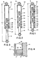
- Figs. 1-3 show an energy absorbing device 10 which incorporates a first preferred embodiment of this invention at three stages of extension.
- Fig 1. shows the device 10 in an initial position prior to use, while Figs. 2 and 3 show the device 10 at progressively greater degrees of extension.
- the device 10 includes a tube 12.
- This tube 12 supports an annular stop 14 at one end, and an attachment 16 at the other.
- a rod 18 is mounted for axial movement within the tube 12, and the rod 18 passes through the stop 14.
- the rod 18 supports an attachment 20 at one end.
- the rod 18 defines three threaded portions 22 and three reduced diameter portions 24.
- Three annular machining elements 26 are provided, each positioned on a respective one of the reduced diameter portions 24. As shown in Fig. 1, in the initial position all three of the machining elements 26 are spaced from the stop 14, and each of the machining elements 26 is spaced from the other machining elements 26.
- the machining elements 26 are dimensioned with a smaller inside diameter than the outside diameter of the threaded portions 22, such that the machining elements 26 cannot move axially along the threaded portions 22 without applying shear loads to and deforming the threaded portions 22.
- the degree of interference can easily be selected as desired by properly dimensioning the inside diameters of the machining elements 26 or the outside diameters of the threaded portions 22.
- Fig. 1 shows the energy absorbing device 10 in an initial position, prior to use. In this position, the effective length of the energy absorbing device is equal to the length L 1 .
- the rod 18 is moved in an axial direction relative to the tube 12 and the stop 14.
- Fig. 2 shows the device 10 in an intermediate position, in which the effective length of the device is equal to the length L 2 .
- the first machining element 26 comes to bear against and thereby engages the stop 14. Further extension of the rod 18 causes the threaded portion 22 adjacent the first machining element 26 to be deformed by the first machining element 26. This deformation continues as the rod 18 moves from the position of Fig. 2 to the position of Fig. 3.
- the second machining element 26 comes to bear against the first machining element 26, and thereby indirectly engages the stop 14. Further extension of the rod 18 causes the first and second machining elements both to move along the threaded portion 22 of the rod 18. The third machining element 26 comes into contact with the second machining element 26 and thereby engages the stop 14 when the energy absorbing device 10 reaches a greater length (not shown).
- Fig. 4 shows an enlarged sectional view that illustrates the operation of one of the machining elements 26.
- the threaded portion 22 of the rod 18 defines an array of alternating ridges 28 and depressed areas or grooves 30. Even though the ridges 28 are all interconnected to form a spiral thread, the ridges 28 effectively form a multitude of projecting elements.
- the machining element 26 defines a machining surface 32 that is positioned to interfere with the ridges 28. Relative axial movement of the rod 18 with respect to the machining element 26 causes the machining surface 32 to apply a shear load which deforms the ridges 28 by cutting, tearing and bending the tops of the ridges 28.
- the deformed ridge material 34 is moved into the adjacent grooves 30.
- the grooves 30 define a receiving volume which is sufficiently large to receive substantially all of the deformed ridge material 34. This prevents the deformed ridge material 34 from building up in front of the machining surface 32, and thereby promotes the creation of reproducible and controllable retarding forces.
- the interference between the machining surface 32 and the ridges 28 be less than one-half the height of the ridges 28.
- the rod 18 moves through an axial stroke with respect to the tube 12, the stop 14 and the machining elements 26. Between lengths L 1 and L 2 there is substantially no resistance to rod extension, and this portion of the stroke can be referred to as a free stroke.
- the rod moves through a retarding stroke in which relative movement between the rod 14 and the machining elements 26 deforms the ridges 28 and thereby creates a retarding force.
- the ridges of the threaded portion 22 extend between first and the second points 36, 38. These first and second points 36, 38 can be selected as desired.
- the actual stroke of the energy absorbing device 10 will depend in part on the energy of impact of an impacting vehicle, and for this reason a varying fraction of the ridges will be deformed in any given event.
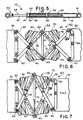
- Fig. 5 shows a longitudinal sectional view of a commercial embodiment of the energy absorbing device 10.
- the stop 14 is welded in place on the tube 12.
- the attachment 16 takes the form of a nut welded in place to the tube 12, and the attachment 20 takes the form of two nuts welded together and threaded to one end of the rod 18.
- this threaded connection is immobilized in some manner, as for example with a suitable thread locking compound.
- the threaded portions 22 of the rod 18 are 2.54 cm (one inch) in outside diameter and the ridges 28 and grooves 30 are formed as 8UNC threads.
- the reduced diameter portions 24 in this embodiment have a diameter of 2.172cm (0.855 inch), and the overall length of the rod 18 is about 55 cm (21-1/2 inches).
- the rod 18 can be formed by turning a Grade B7 threaded rod to remove the threads in the reduced diameter portions.
- the machining elements or dies 26 are solid, rigid, annular rings which are threaded to facilitate installation on the rod 18.
- These rings define an inside diameter of 2.426cm (0.955 inch) and an outside diameter of 3.683cm (1.450 inch), and are preferably formed by turning a grade DH nut (1) to remove part of the threads to achieve the desired inside diameter and (2) to remove the hexagonal wrench flats.
- a grade DH nut is preferred because it is harder than the rod 18.
- the inner diameters of the two machining elements 26 are identical, and the outer diameter of the threaded portions 22 is constant.
- the retarding force generated by relative movement between the rod 18 and the machining elements 26 amounts to about 53kN (12,000 lbs. force).
- the machining surfaces of the machining elements 26 are worn to some extent.
- wear of this type is compensated, and any substantial reduction in the retarding force is avoided.
- the inside diameter of the second machining element 26 can be made smaller than that of the first in order to increase the retarding force midway through the stroke.
- FIGs. 6 and 7 show one preferred embodiment of a mounting arrangement 50 which includes a forward portion 52 such as a truck mounted attenuator cartridge and a reaction portion 54 such as a truck to which the truck mounted attenuator ("TMA") cartridge is mounted.
- the mounting arrangement 50 includes a scissors linkage 56 made up of two pairs of crossing links 58 which pivot about pivot axes 60.
- the links 58 support sheet metal deformable elements 62.
- the mounting arrangement 50 of Figs. 6 and 7 is described in complete detail in EP-A-0586071 to which reference should be made.
- Fig. 6 shows the mounting arrangement 50 in its initial state.
- the energy absorbing device 10 is mounted between the central pivot axes 60, and has an initial, unextended length as shown in Fig. 5.
- FIG. 7 shows the linkage 56 at an intermediate stage of collapse, in which the intermediate pivot axes 60 have moved substantially away from one another. This action extends the energy absorbing device 10, and forces the machining elements 26 to move along the rod 18 and to deform the ridges 28. Retarding forces generated by the energy absorbing device 10 oppose outward movement of the intermediate pivot axes 60, and thereby apply a retarding force on the impacting vehicle. Further collapse of the linkage 56 causes the deformable elements 62 to be crushed against the ends of the linkage 56, as described in complete detail in the above referenced EP - A - 0586071.
- two of the energy absorbing devices 10 are used with the scissors linkage 56, each positioned adjacent to a respective side of the linkage 56.
- the deformable elements 62 are preferably made of 12 gauge steel in this example.
- FIG. 8 shows a third preferred embodiment of an energy absorbing device 80 which includes a tube 82 which supports at one end an attachment 84.
- the interior of the tube 82 defines an array of threads 86, and a machining element 88 is positioned within the tube 82.
- This machining element 88 defines a machining surface 90 that is dimensioned to interfere with the threads 86.
- a rod 92 is secured to the machining element 88 and extends axially out the open end (not shown) of the tube 82. When the rod 92 is extended out of the tube 82, the machining element 88 deforms the threads 86 in the manner described above to create a retarding force.
- Fig. 9 shows a fourth embodiment of this invention which comprises an energy absorbing device 100.
- the machining element 102 is annular, and it defines a rectangular opening 104. The margins of this opening define a machining surface 106.
- a rod 108 extends through the opening 104, and in this embodiment the rod 108 is rectangular in cross-section and shaped as a plate or strap.
- one or more surfaces of the rod 108 define projecting elements 110 separated by depressed areas 112, and the projecting elements 110 are shaped as discrete peaks rather than ridges. Movement of the rod 108 through the opening 104 causes the machining surface 106 to deform the projecting elements 110 and to create a retarding force in the manner described above.
- the projecting elements can be shaped as discrete projecting elements, parallel ridges or threads, and they can be cut, stamped, deposited, or machined in place.
- the machining element can be placed inside the deformable projecting elements or the reverse.
- the device can be designed either for use in extension, as described above, or in compression. When multiple machining elements are used the dimensions of the machining surfaces can be constant, or they can increase or decrease from one machining element to another.
- either the machining element or the projection defining element is annular in shape, though the opening can be either round, rectangular or any other desired cross-sectional shape.
- the height, density, and thickness of the projecting elements can be varied to adjust or modulate the retarding force during the stroke.
- the machining elements 26 are initially spaced from the stop 14 to create the free stroke described above.
- This arrangement operates as a means for preventing initial movement of the rod 18 from deforming the threaded portions 22.
- the same result can be achieved by fixedly mounting the machining elements in place on the tube 12 and properly dimensioning the reduced diameter portions 24.
- the energy absorbing device 10 is used in a scissors linkage on a mounting arrangement for a truck mounted attenuator.
- This invention is not limited to this application, and it can readily be adapted to other energy absorbing mounting arrangements alongside a roadway.
- the energy absorbing device 10 can be used in a collapsible system of the type shown in U.S. Patents 3,944,187 and 4,583,716, in which parallel diaphragms are arranged to move together in an impact.
- the energy absorbing device 10 can be adapted for use in a system of the type shown in U.S. Patent 5,022,782.
- the threaded rod 18 can be elongated and substituted for the cable, and the machining element 26 can be used in place of the brake arrangement of that patent.
- an energy absorbing device which is well suited to generate a retarding force that is predictable, repeatable and well-controlled.
- the retarding force profile can be controlled as desired to remain constant, increase or decrease over the retarding stroke.
- This device also allows the free stroke length to be adjusted easily as appropriate for the particular application.
- the device is simple and reliable, and it does not rely on frictional characteristics to generate the retarding force.
- the need for spring clamps has been eliminated, and the device can easily be adapted to a wide range of applications.
Landscapes
- Engineering & Computer Science (AREA)
- Mechanical Engineering (AREA)
- General Engineering & Computer Science (AREA)
- Architecture (AREA)
- Civil Engineering (AREA)
- Structural Engineering (AREA)
- Vibration Dampers (AREA)
- Non-Reversible Transmitting Devices (AREA)
- Measurement Of Length, Angles, Or The Like Using Electric Or Magnetic Means (AREA)
- Springs (AREA)
- Other Liquid Machine Or Engine Such As Wave Power Use (AREA)
Claims (14)
- Energieabsorbierende Vorrichtung (10, 80, 100), die an einer Straße zum Abbremsen eines aufprallenden Fahrzeugs eingesetzt wird, wobei die Vorrichtung umfaßt:eine Anbringungsanordnung (50), die umfaßt:einen vorderen Abschnitt (52), der so geformt ist, daß er mit dem aufprallenden Fahrzeug in Kontakt kommt;einen Gegenwirkungsabschnitt (54), der so geformt ist, daß er dem aufprallenden Fahrzeug Widerstand entgegensetzt; undein Verbindungsgestänge (56), das ein erstes und ein zweites Element (18, 26) mit dem vorderen Abschnitt (52) und dem Gegenwirkungsabschnitt (54) so verbindet, daß, wenn das aufprallende Fahrzeug den vorderen Abschnitt (52) auf den Gegenwirkungsabschnitt (54) zu bewegt, das Verbindungsgestänge (56) bewirkt, daß sich der erste und der zweite Abschnitt des Verbindungsgestänges voneinander weg bewegen; dadurch gekennzeichnet, daß:das erste und das zweiten Element (18, 82, 108; 26, 88, 102) jeweils eine entsprechende Anbringung umfassen, die an dem ersten bzw. dem zweiten Abschnitt des Verbindungsgestänges angebracht ist;sich das erste Element (18, 82, 108) in einer axialen Richtung erstreckt und eine Vielzahl vorstehender Elemente (28, 86, 110) umfaßt, die nacheinander in der axialen Richtung auf einem Abschnitt des ersten Elementes (18, 82, 108) verteilt sind, der sich axial zwischen einer ersten und einer zweiten Position erstreckt;das zweite Element (26, 88, 102) so angebracht ist, daß es sich in bezug auf das erste Element (18, 82, 108) in der axialen Richtung bewegt, wobei das erste und das zweite Element (18, 82, 108; 26, 88, 102) so bemessen sind, daß eine Preßpassung erzeugt wird, so daß relative axiale Bewegung des zweiten Elementes (26, 88, 102) zwischen der ersten und der zweiten Position eine Scherbeanspruchung des ersten Elementes (18, 82, 108) bewirkt, so daß aufeinanderfolgende der vorstehenden Elemente (28, 86, 110) zunehmend verformt werden, wobei die zunehmende Verformung der vorstehenden Elemente (28, 86, 110) die relative axiale Bewegung verzögert, wobei sich die Preßpassung vor der zunehmenden Verformung zwischen der Anbringung des ersten Elementes und wenigstens einem Teil der vorstehenden Elemente befindet.
- Energieabsorbierende Vorrichtung nach Anspruch 1, wobei die vorstehenden Elemente (28, 86) eine wechselnde Anordnung von Stegen (28) und Rinnen (30) umfassen.
- Energieabsorbierende Vorrichtung nach Anspruch 1 oder Anspruch 2, wobei entweder das erste oder das zweite Element (26, 82, 102) eine Öffnung aufweist, in der das andere, d.h., das erste oder das zweite Element (18, 88, 108), aufgenommen ist.
- Energieabsorbierende Vorrichtung nach Anspruch 3, wobei entweder das erste oder das zweite Element (26, 82, 102) um die Öffnung herum fortläuft und die Öffnung eine vorgegebene Querschnittsabmessung aufweist.
- Energieabsorbierende Vorrichtung nach einem der Ansprüche 1 bis 4, wobei die erste und die zweite Position einen Verzögerungshub begrenzen, der sich zwischen ihnen erstreckt, und wobei das zweite Element (26, 88, 102) während des gesamten Verzögerungshubes, wenn sich das zweite Element (28, 88, 102) zwischen der ersten und der zweiten Position bewegt, aufeinanderfolgende der vorstehenden Elemente (28, 86, 110) zunehmend verformt.
- Energieabsorbierende Vorrichtung nach einem der Ansprüche 1 bis 5, wobei das zweite Element (26, 88, 102) eine Glättfläche (32, 90, 106) an die vorstehenden Elemente (28, 86, 110) angrenzend umfaßt, und wobei die Glättfläche (32, 90, 106) härter ist als die vorstehenden Elemente (28, 86, 110).
- Energieabsorbierende Vorrichtung nach Anspruch 6, die des weiteren ein zusätzliches zweites Element (26) umfaßt, das eine zusätzliche Glättfläche (32) aufweist, die so geformt ist, daß sie die vorstehenden Elemente (28) verformt, wobei das zusätzliche Element (26) vor dem Aufprall entlang des ersten Elementes (18) axial von der erstgenannten Glättfläche (32) beabstandet ist.
- Energieabsorbierende Vorrichtung nach Anspruch 7, wobei die zusätzliche Glättfläche (32) in Preßpassung mit den vorstehenden Elementen (28) ist, wobei der Grad der Preßpassung höher ist als bei der erstgenannten Glättfläche (32).
- Energieabsorbierende Vorrichtung nach einem der Ansprüche 1 bis 8, wobei die vorstehenden Elemente (28, 86, 110) durch vertiefte Bereiche (30, 112) an dem ersten Element (18, 82, 108) getrennt sind, und wobei die vertieften Bereiche (30, 112) einen Aufnahmeraum bilden, der groß genug ist, um verformte Abschnitte der vorstehenden Elemente (28, 86, 110) bei relativer axialer Bewegung des zweiten Elementes (26, 88, 102) zwischen der ersten und der zweiten Position aufzunehmen.
- Energieabsorbierende Vorrichtung nach einem der vorangehenden Ansprüche, wobei das Verbindungsgestänge (56) eine Vielzahl von Verbindungsstangen (58) umfaßt, die an Drehachsen (60) miteinander verbunden sind, so daß eine Scherengelenkverbindung entsteht, und wobei das erste und das zweite Element (18, 26) an entsprechenden Abschnitten der Scherengelenkverbindung so angebracht sind, daß die Scherengelenkverbindung das erste Element (18) über einen axialen Hub in bezug auf das zweite Element (26) zieht, wenn die Scherengelenkverbindung zusammengedrückt wird.
- Energieabsorbierende Vorrichtung nach einem der Ansprüche 1 bis 10, die des weiteren wenigstens ein zusätzliches zweites Element (26) umfaßt, das vor dem Aufprall von dem erstgenannten zweiten Element (26) axial beabstandet ist.
- Energieabsorbierende Vorrichtung nach Anspruch 11, wobei jedes der zweiten Elemente (26) in einer entsprechenden Preßpassung mit dem ersten Element (18) ist, und wobei sich der Grad der Preßpassung unterscheidet.
- Energieabsorbierende Vorrichtung nach einem der Ansprüche 1 bis 12, wobei das zweite Element ein Glättelement (26) umfaßt, das so bemessen ist, daß es die Preßpassung erzeugt, wobei entweder das erste oder das zweite Element (18, 82, 108; 26, 88, 102) einen Anschlag (14) umfaßt, der anfänglich axial von dem Glättelement (26) beabstandet ist und nach einer anfänglichen Bewegungsstrecke mit dem Glättelement (26) in Kontakt kommt, so daß das Glättelement (26) beginnt, die vorstehenden Elemente (28) zu verformen.
- Energieabsorbierende Vorrichtung nach einem der Ansprüche 1 bis 12, die des weiteren eine Einrichtung (24) umfaßt, die verhindert, daß das zweite Element bei einem anfänglichen freien Hub der Bewegung des ersten und des zweiten Elementes zueinander die vorstehenden Elemente verformt.
Applications Claiming Priority (2)
| Application Number | Priority Date | Filing Date | Title |
|---|---|---|---|
| US08/048,151 US5403113A (en) | 1992-08-12 | 1993-04-15 | Shear loading energy absorbing device |
| US48151 | 1993-04-15 |
Publications (2)
| Publication Number | Publication Date |
|---|---|
| EP0621375A1 EP0621375A1 (de) | 1994-10-26 |
| EP0621375B1 true EP0621375B1 (de) | 1996-11-27 |
Family
ID=21953000
Family Applications (1)
| Application Number | Title | Priority Date | Filing Date |
|---|---|---|---|
| EP94302496A Expired - Lifetime EP0621375B1 (de) | 1993-04-15 | 1994-04-08 | Stossverzehrelement mit stetigem Verformungswiderstand |
Country Status (7)
| Country | Link |
|---|---|
| US (1) | US5403113A (de) |
| EP (1) | EP0621375B1 (de) |
| JP (1) | JP3495411B2 (de) |
| AT (1) | ATE145689T1 (de) |
| CA (1) | CA2120780C (de) |
| DE (1) | DE69400974T2 (de) |
| ES (1) | ES2095131T3 (de) |
Families Citing this family (37)
| Publication number | Priority date | Publication date | Assignee | Title |
|---|---|---|---|---|
| US6022003A (en) * | 1994-11-07 | 2000-02-08 | The Board Of Regents Of The University Of Nebraska | Guardrail cutting terminal |
| US6220575B1 (en) | 1995-01-18 | 2001-04-24 | Trn Business Trust | Anchor assembly for highway guardrail end terminal |
| DE19617565C2 (de) * | 1996-05-02 | 2000-09-21 | Daimler Chrysler Ag | Nutzkraftfahrzeug mit einem Fahrerhaus und einem von diesem getrennten Transportbehälter |
| GB2322602A (en) * | 1997-02-17 | 1998-09-02 | Lin Pac Mouldings | Bumper assemblies for motor vehicles |
| KR100246635B1 (ko) * | 1997-09-24 | 2000-04-01 | 허광용 | 충격흡수 완화장치 |
| SE513070C2 (sv) * | 1998-02-10 | 2000-07-03 | Gunnar Englund Byggare Ab | Skyddsbarriär avsedd att placeras mellan skilda körbanor hos en väg |
| US6099200A (en) * | 1998-10-02 | 2000-08-08 | Pepe; John J. | Anti-terror bollard |
| US7243964B1 (en) | 1999-04-28 | 2007-07-17 | Traffix Devices, Inc | Truck mounted crash attenuator |
| US6581992B1 (en) | 1999-04-28 | 2003-06-24 | Traffix Devices, Inc. | Truck mounted crash attenuator |
| US6461076B1 (en) | 2001-01-03 | 2002-10-08 | Energy Absorption Systems, Inc. | Vehicle impact attenuator |
| US6416093B1 (en) | 2001-06-11 | 2002-07-09 | Phillip Schneider | Energy absorption, rotation and redirection system for use with racing vehicles and a surrounding barrier |
| US20030077119A1 (en) * | 2001-09-28 | 2003-04-24 | Energy Absorption System, Inc. | Vehicle mounted crash attenuator |
| US7255369B2 (en) * | 2001-12-06 | 2007-08-14 | Nsk Ltd. | Shock absorption type steering column device |
| US6702511B2 (en) | 2002-01-16 | 2004-03-09 | Rockford Roy Russell | Crash guard with monitoring |
| US6863467B2 (en) * | 2002-02-27 | 2005-03-08 | Energy Absorption Systems, Inc. | Crash cushion with deflector skin |
| FR2840041B1 (fr) * | 2002-05-23 | 2004-07-16 | Snecma Moteurs | Biellette fusible avec amortisseur et butee antiretour |
| DE10227742A1 (de) * | 2002-06-21 | 2004-01-15 | Benteler Automobiltechnik Gmbh | Kraftfahrzeug |
| CN1319783C (zh) * | 2003-04-28 | 2007-06-06 | 管红钧 | 车辆碰撞保护器 |
| WO2004096611A1 (fr) * | 2003-04-28 | 2004-11-11 | Hongjun Guan | Dispositif de protection contre les chocs |
| DE10336713A1 (de) * | 2003-08-11 | 2005-03-17 | Michael Rossmann | Fahrzeug-Anpralldämpfer |
| US6962459B2 (en) * | 2003-08-12 | 2005-11-08 | Sci Products Inc. | Crash attenuator with cable and cylinder arrangement for decelerating vehicles |
| US20050077716A1 (en) * | 2003-10-08 | 2005-04-14 | Urista Jesus Raul Garcia | Steering column energy absorber |
| SE526813C2 (sv) * | 2004-03-04 | 2005-11-08 | Vaegverket | Krockdämpande anordning för fordon och metod |
| US7874572B2 (en) * | 2005-01-10 | 2011-01-25 | Energy Absorption Systems, Inc. | Towable impact attenuator |
| US20080174095A1 (en) * | 2007-01-18 | 2008-07-24 | Ridgway Jason R | Energy absorption mechanism for collapsible assembly |
| WO2008095048A1 (en) * | 2007-01-30 | 2008-08-07 | Traffix Devices, Inc. | Trailer mounted crash attenuator |
| US7441817B1 (en) * | 2007-04-23 | 2008-10-28 | Tma Acquisition, Llc | Trailer mounted crash attenuation system |
| FR2920997B1 (fr) * | 2007-09-19 | 2010-02-26 | Ajuva Safety | Dispositif absorbeur d'energie et dispositif de fixation incorporant un tel dispositif absorbeur d'energie, notamment pour la fixation de lignes de vie |
| US7931317B2 (en) * | 2008-03-11 | 2011-04-26 | Kern Charles L | Reusable trailer mounted attenuator |
| US7722284B1 (en) * | 2008-09-10 | 2010-05-25 | Banyat Somwong | Traffic impact attenuator |
| SE535428C2 (sv) * | 2010-12-02 | 2012-08-07 | Birstaverken Ab | Påkörningsskydd för fordon innefattande en energiabsorberande anordning |
| CN103410904A (zh) * | 2013-08-16 | 2013-11-27 | 西北核技术研究所 | 一种圆管组合缓冲装置 |
| CN105555646B (zh) | 2013-09-11 | 2018-04-06 | 能量吸收系统公司 | 碰撞衰减器及使用其衰减来自撞击车辆的能量的方法 |
| CN114454788B (zh) * | 2017-12-14 | 2023-12-05 | 宝钜儿童用品香港股份有限公司 | 缓冲结构及儿童安全座椅 |
| CN109229038A (zh) * | 2018-08-02 | 2019-01-18 | 孙丕祥 | 车辆碰撞缓冲装置 |
| PE20221234A1 (es) | 2019-05-15 | 2022-08-12 | Trinity Highway Products Llc | Atenuador de golpes con conjunto de bisagra de placa de liberacion, conjunto de bisagra de placa de liberacion y metodo para el uso del mismo |
| CN111994024A (zh) * | 2020-09-04 | 2020-11-27 | 邓云娣 | 一种承载式防撞装置及应用其的车辆、护栏、桥梁和建筑 |
Family Cites Families (26)
| Publication number | Priority date | Publication date | Assignee | Title |
|---|---|---|---|---|
| US1828349A (en) * | 1930-12-26 | 1931-10-20 | Malleable Iron Fittings Co | Automatic compensating device for highway guard fence cables |
| US2058283A (en) * | 1933-06-10 | 1936-10-20 | Wolff Ivan | Automobile bumper |
| US3211260A (en) * | 1964-07-21 | 1965-10-12 | Zelm Associates Inc Van | Energy absorption device |
| GB1066988A (en) * | 1964-11-11 | 1967-04-26 | Christiani & Nielsen Ltd | Improvements in or relating to highway guard rail supports |
| US3308908A (en) * | 1965-01-11 | 1967-03-14 | Lockheed Aircraft Corp | Energy absorber |
| US3307832A (en) * | 1965-03-01 | 1967-03-07 | Zelm Associates Inc Van | Cargo lowering device |
| US3377044A (en) * | 1966-03-02 | 1968-04-09 | Zelm Associates Inc Van | Cargo tie-down apparatus |
| US3606258A (en) * | 1969-01-02 | 1971-09-20 | Fibco Inc | Energy absorbing deceleration barriers |
| US3672657A (en) * | 1970-09-23 | 1972-06-27 | Energy Absorption System | Liquid shock absorbing buffer |
| DE2107702A1 (de) * | 1971-02-18 | 1972-09-07 | Daimler-Benz Ag, 7000 Stuttgart | Anordnung eines Stoßfängers bei Fahrzeugen |
| US3944187A (en) * | 1974-09-13 | 1976-03-16 | Dynamics Research And Manufacturing, Inc. | Roadway impact attenuator |
| LU71229A1 (de) * | 1974-10-31 | 1976-08-19 | ||
| US4030706A (en) * | 1976-09-08 | 1977-06-21 | James S. Ward | Highway guard rail bumper guard |
| JPS5451739U (de) * | 1977-08-15 | 1979-04-10 | ||
| AU542884B2 (en) * | 1980-07-31 | 1985-03-21 | Dipl.Ing. Dr. Mont. Franz Powondra | Resilient yieldable device |
| US4352484A (en) * | 1980-09-05 | 1982-10-05 | Energy Absorption Systems, Inc. | Shear action and compression energy absorber |
| US4583716A (en) * | 1982-05-19 | 1986-04-22 | Energy Absorption Systems, Inc. | Universal anchor assembly for impact attenuation device |
| FR2528928A1 (fr) * | 1982-06-21 | 1983-12-23 | Picand Roland | Dispositif absorbeur d'energie par decoupage continu |
| US4711481A (en) * | 1985-10-25 | 1987-12-08 | Energy Absorption Systems, Inc. | Vehicle impact attenuating device |
| JPH0626456Y2 (ja) * | 1988-02-22 | 1994-07-20 | 日産自動車株式会社 | ショックアブソーバ式バンパの車体取付構造 |
| US4823923A (en) * | 1988-09-06 | 1989-04-25 | Moyer James E | Energy dampening apparatus |
| US4934661A (en) * | 1989-03-31 | 1990-06-19 | Energy Absorption Systems, Inc. | Inertial barrier array |
| US5022782A (en) * | 1989-11-20 | 1991-06-11 | Energy Absorption Systems, Inc. | Vehicle crash barrier |
| DE4037101A1 (de) * | 1989-12-01 | 1991-06-06 | Volkswagen Ag | Pralldaempfer, insbesondere fuer eine stossfaengeranordnung eines kraftfahrzeugs |
| AT394004B (de) * | 1990-06-25 | 1992-01-27 | Austria Metall | Stossverzehrkoerper, insbesondere fuer kraftfahrzeuge |
| US5199755A (en) * | 1991-04-03 | 1993-04-06 | Energy Absorption Systems, Inc. | Vehicle impact attenuating device |
-
1993
- 1993-04-15 US US08/048,151 patent/US5403113A/en not_active Expired - Lifetime
-
1994
- 1994-04-07 CA CA002120780A patent/CA2120780C/en not_active Expired - Fee Related
- 1994-04-08 DE DE69400974T patent/DE69400974T2/de not_active Expired - Fee Related
- 1994-04-08 ES ES94302496T patent/ES2095131T3/es not_active Expired - Lifetime
- 1994-04-08 EP EP94302496A patent/EP0621375B1/de not_active Expired - Lifetime
- 1994-04-08 AT AT94302496T patent/ATE145689T1/de active
- 1994-04-14 JP JP07610494A patent/JP3495411B2/ja not_active Expired - Fee Related
Also Published As
| Publication number | Publication date |
|---|---|
| JPH06307480A (ja) | 1994-11-01 |
| CA2120780C (en) | 1999-01-19 |
| ES2095131T3 (es) | 1997-02-01 |
| DE69400974D1 (de) | 1997-01-09 |
| AU5934094A (en) | 1994-10-20 |
| EP0621375A1 (de) | 1994-10-26 |
| JP3495411B2 (ja) | 2004-02-09 |
| US5403113A (en) | 1995-04-04 |
| DE69400974T2 (de) | 1997-06-12 |
| ATE145689T1 (de) | 1996-12-15 |
| CA2120780A1 (en) | 1994-10-16 |
| AU667265B2 (en) | 1996-03-14 |
Similar Documents
| Publication | Publication Date | Title |
|---|---|---|
| CA2120780C (en) | Shear loading energy absorbing device | |
| AU761337B2 (en) | Method for decelerating a vehicle, highway crash cushion, and energy absorbing element therefor | |
| JP2942345B2 (ja) | 車両用クラッシュバリヤ | |
| CA2101619C (en) | Energy absorbing roadside crash barrier | |
| CA2219144C (en) | Energy absorbing structure | |
| US6244637B1 (en) | Adjustable tailgate mount for truck mounted attenuator | |
| US5487562A (en) | Energy absorbing apparatus for a motor vehicle | |
| AU733139B2 (en) | Roadside energy absorbing barrier with improved fender panel fastener | |
| US6767057B2 (en) | Vehicle anchorage system for child seat | |
| US6231095B1 (en) | Energy absorption impact system | |
| US2870871A (en) | Shock absorber | |
| US5104136A (en) | Steering tie rod for motor vehicle | |
| CA2122437A1 (en) | Energy absorbing device | |
| US6454201B1 (en) | Friction clutch and belt retractor with friction clutch | |
| US5005863A (en) | Installable component for absorbing energy | |
| EP1305199B1 (de) | Hülsenpuffer | |
| EP0739461B1 (de) | Verzögerungssystem zur reduktion der geschwindigkeit von bewegenden objekten | |
| EP1624112B1 (de) | Leitplankenelement mit verformbaren Teile zwischen dem Element und den Verankerungsbolzen | |
| GB2089466A (en) | Energy absorbing devices |
Legal Events
| Date | Code | Title | Description |
|---|---|---|---|
| PUAI | Public reference made under article 153(3) epc to a published international application that has entered the european phase |
Free format text: ORIGINAL CODE: 0009012 |
|
| AK | Designated contracting states |
Kind code of ref document: A1 Designated state(s): AT BE CH DE DK ES FR GB GR IE IT LI LU MC NL PT SE |
|
| RAX | Requested extension states of the european patent have changed |
Free format text: SI PAYMENT 940416 |
|
| 17P | Request for examination filed |
Effective date: 19950407 |
|
| 17Q | First examination report despatched |
Effective date: 19951115 |
|
| GRAG | Despatch of communication of intention to grant |
Free format text: ORIGINAL CODE: EPIDOS AGRA |
|
| GRAH | Despatch of communication of intention to grant a patent |
Free format text: ORIGINAL CODE: EPIDOS IGRA |
|
| GRAH | Despatch of communication of intention to grant a patent |
Free format text: ORIGINAL CODE: EPIDOS IGRA |
|
| GRAA | (expected) grant |
Free format text: ORIGINAL CODE: 0009210 |
|
| AK | Designated contracting states |
Kind code of ref document: B1 Designated state(s): AT BE CH DE DK ES FR GB GR IE IT LI LU MC NL PT SE |
|
| AX | Request for extension of the european patent |
Free format text: SI PAYMENT 940416 |
|
| PG25 | Lapsed in a contracting state [announced via postgrant information from national office to epo] |
Ref country code: GR Free format text: LAPSE BECAUSE OF FAILURE TO SUBMIT A TRANSLATION OF THE DESCRIPTION OR TO PAY THE FEE WITHIN THE PRESCRIBED TIME-LIMIT Effective date: 19961127 Ref country code: DK Effective date: 19961127 Ref country code: BE Effective date: 19961127 Ref country code: AT Effective date: 19961127 |
|
| REF | Corresponds to: |
Ref document number: 145689 Country of ref document: AT Date of ref document: 19961215 Kind code of ref document: T |
|
| ET | Fr: translation filed | ||
| REG | Reference to a national code |
Ref country code: IE Ref legal event code: FG4D Free format text: 70794 |
|
| REF | Corresponds to: |
Ref document number: 69400974 Country of ref document: DE Date of ref document: 19970109 |
|
| REG | Reference to a national code |
Ref country code: CH Ref legal event code: NV Representative=s name: KIRKER & CIE SA |
|
| REG | Reference to a national code |
Ref country code: ES Ref legal event code: FG2A Ref document number: 2095131 Country of ref document: ES Kind code of ref document: T3 |
|
| ITF | It: translation for a ep patent filed | ||
| REG | Reference to a national code |
Ref country code: PT Ref legal event code: SC4A Free format text: AVAILABILITY OF NATIONAL TRANSLATION Effective date: 19961204 |
|
| PG25 | Lapsed in a contracting state [announced via postgrant information from national office to epo] |
Ref country code: IE Free format text: LAPSE BECAUSE OF NON-PAYMENT OF DUE FEES Effective date: 19970408 |
|
| PG25 | Lapsed in a contracting state [announced via postgrant information from national office to epo] |
Ref country code: LU Free format text: LAPSE BECAUSE OF NON-PAYMENT OF DUE FEES Effective date: 19970430 |
|
| PLBE | No opposition filed within time limit |
Free format text: ORIGINAL CODE: 0009261 |
|
| STAA | Information on the status of an ep patent application or granted ep patent |
Free format text: STATUS: NO OPPOSITION FILED WITHIN TIME LIMIT |
|
| PG25 | Lapsed in a contracting state [announced via postgrant information from national office to epo] |
Ref country code: MC Effective date: 19971031 |
|
| 26N | No opposition filed | ||
| REG | Reference to a national code |
Ref country code: GB Ref legal event code: IF02 |
|
| PGFP | Annual fee paid to national office [announced via postgrant information from national office to epo] |
Ref country code: FR Payment date: 20050401 Year of fee payment: 12 |
|
| PGFP | Annual fee paid to national office [announced via postgrant information from national office to epo] |
Ref country code: PT Payment date: 20060322 Year of fee payment: 13 |
|
| PGFP | Annual fee paid to national office [announced via postgrant information from national office to epo] |
Ref country code: ES Payment date: 20060424 Year of fee payment: 13 Ref country code: CH Payment date: 20060424 Year of fee payment: 13 |
|
| PGFP | Annual fee paid to national office [announced via postgrant information from national office to epo] |
Ref country code: NL Payment date: 20070315 Year of fee payment: 14 |
|
| PGFP | Annual fee paid to national office [announced via postgrant information from national office to epo] |
Ref country code: DE Payment date: 20070430 Year of fee payment: 14 |
|
| REG | Reference to a national code |
Ref country code: PT Ref legal event code: MM4A Free format text: LAPSE DUE TO NON-PAYMENT OF FEES Effective date: 20071008 |
|
| REG | Reference to a national code |
Ref country code: CH Ref legal event code: PL |
|
| PGFP | Annual fee paid to national office [announced via postgrant information from national office to epo] |
Ref country code: IT Payment date: 20070529 Year of fee payment: 14 |
|
| PG25 | Lapsed in a contracting state [announced via postgrant information from national office to epo] |
Ref country code: PT Free format text: LAPSE BECAUSE OF NON-PAYMENT OF DUE FEES Effective date: 20071008 |
|
| PG25 | Lapsed in a contracting state [announced via postgrant information from national office to epo] |
Ref country code: CH Free format text: LAPSE BECAUSE OF NON-PAYMENT OF DUE FEES Effective date: 20070430 Ref country code: LI Free format text: LAPSE BECAUSE OF NON-PAYMENT OF DUE FEES Effective date: 20070430 |
|
| REG | Reference to a national code |
Ref country code: ES Ref legal event code: FD2A Effective date: 20070409 |
|
| PG25 | Lapsed in a contracting state [announced via postgrant information from national office to epo] |
Ref country code: FR Free format text: LAPSE BECAUSE OF NON-PAYMENT OF DUE FEES Effective date: 20070430 |
|
| PG25 | Lapsed in a contracting state [announced via postgrant information from national office to epo] |
Ref country code: FR Free format text: LAPSE BECAUSE OF NON-PAYMENT OF DUE FEES Effective date: 20060430 |
|
| PG25 | Lapsed in a contracting state [announced via postgrant information from national office to epo] |
Ref country code: ES Free format text: LAPSE BECAUSE OF NON-PAYMENT OF DUE FEES Effective date: 20070409 |
|
| PGFP | Annual fee paid to national office [announced via postgrant information from national office to epo] |
Ref country code: GB Payment date: 20080429 Year of fee payment: 15 |
|
| NLV4 | Nl: lapsed or anulled due to non-payment of the annual fee |
Effective date: 20081101 |
|
| PG25 | Lapsed in a contracting state [announced via postgrant information from national office to epo] |
Ref country code: NL Free format text: LAPSE BECAUSE OF NON-PAYMENT OF DUE FEES Effective date: 20081101 Ref country code: DE Free format text: LAPSE BECAUSE OF NON-PAYMENT OF DUE FEES Effective date: 20081101 |
|
| PG25 | Lapsed in a contracting state [announced via postgrant information from national office to epo] |
Ref country code: IT Free format text: LAPSE BECAUSE OF NON-PAYMENT OF DUE FEES Effective date: 20080408 |
|
| GBPC | Gb: european patent ceased through non-payment of renewal fee |
Effective date: 20090408 |
|
| PG25 | Lapsed in a contracting state [announced via postgrant information from national office to epo] |
Ref country code: GB Free format text: LAPSE BECAUSE OF NON-PAYMENT OF DUE FEES Effective date: 20090408 |
|
| PGFP | Annual fee paid to national office [announced via postgrant information from national office to epo] |
Ref country code: SE Payment date: 20130405 Year of fee payment: 20 |
|
| REG | Reference to a national code |
Ref country code: SE Ref legal event code: EUG |