EP0619623B1 - Verpresste Leiterklemme - Google Patents
Verpresste Leiterklemme Download PDFInfo
- Publication number
- EP0619623B1 EP0619623B1 EP94301832A EP94301832A EP0619623B1 EP 0619623 B1 EP0619623 B1 EP 0619623B1 EP 94301832 A EP94301832 A EP 94301832A EP 94301832 A EP94301832 A EP 94301832A EP 0619623 B1 EP0619623 B1 EP 0619623B1
- Authority
- EP
- European Patent Office
- Prior art keywords
- conductor
- grips
- terminal
- crimping
- grooves
- Prior art date
- Legal status (The legal status is an assumption and is not a legal conclusion. Google has not performed a legal analysis and makes no representation as to the accuracy of the status listed.)
- Expired - Lifetime
Links
Images

Classifications
-
- H—ELECTRICITY
- H01—ELECTRIC ELEMENTS
- H01R—ELECTRICALLY-CONDUCTIVE CONNECTIONS; STRUCTURAL ASSOCIATIONS OF A PLURALITY OF MUTUALLY-INSULATED ELECTRICAL CONNECTING ELEMENTS; COUPLING DEVICES; CURRENT COLLECTORS
- H01R4/00—Electrically-conductive connections between two or more conductive members in direct contact, i.e. touching one another; Means for effecting or maintaining such contact; Electrically-conductive connections having two or more spaced connecting locations for conductors and using contact members penetrating insulation
- H01R4/10—Electrically-conductive connections between two or more conductive members in direct contact, i.e. touching one another; Means for effecting or maintaining such contact; Electrically-conductive connections having two or more spaced connecting locations for conductors and using contact members penetrating insulation effected solely by twisting, wrapping, bending, crimping, or other permanent deformation
- H01R4/18—Electrically-conductive connections between two or more conductive members in direct contact, i.e. touching one another; Means for effecting or maintaining such contact; Electrically-conductive connections having two or more spaced connecting locations for conductors and using contact members penetrating insulation effected solely by twisting, wrapping, bending, crimping, or other permanent deformation by crimping
- H01R4/183—Electrically-conductive connections between two or more conductive members in direct contact, i.e. touching one another; Means for effecting or maintaining such contact; Electrically-conductive connections having two or more spaced connecting locations for conductors and using contact members penetrating insulation effected solely by twisting, wrapping, bending, crimping, or other permanent deformation by crimping for cylindrical elongated bodies, e.g. cables having circular cross-section
- H01R4/184—Electrically-conductive connections between two or more conductive members in direct contact, i.e. touching one another; Means for effecting or maintaining such contact; Electrically-conductive connections having two or more spaced connecting locations for conductors and using contact members penetrating insulation effected solely by twisting, wrapping, bending, crimping, or other permanent deformation by crimping for cylindrical elongated bodies, e.g. cables having circular cross-section comprising a U-shaped wire-receiving portion
- H01R4/185—Electrically-conductive connections between two or more conductive members in direct contact, i.e. touching one another; Means for effecting or maintaining such contact; Electrically-conductive connections having two or more spaced connecting locations for conductors and using contact members penetrating insulation effected solely by twisting, wrapping, bending, crimping, or other permanent deformation by crimping for cylindrical elongated bodies, e.g. cables having circular cross-section comprising a U-shaped wire-receiving portion combined with a U-shaped insulation-receiving portion
-
- H—ELECTRICITY
- H01—ELECTRIC ELEMENTS
- H01R—ELECTRICALLY-CONDUCTIVE CONNECTIONS; STRUCTURAL ASSOCIATIONS OF A PLURALITY OF MUTUALLY-INSULATED ELECTRICAL CONNECTING ELEMENTS; COUPLING DEVICES; CURRENT COLLECTORS
- H01R4/00—Electrically-conductive connections between two or more conductive members in direct contact, i.e. touching one another; Means for effecting or maintaining such contact; Electrically-conductive connections having two or more spaced connecting locations for conductors and using contact members penetrating insulation
- H01R4/26—Connections in which at least one of the connecting parts has projections which bite into or engage the other connecting part in order to improve the contact
Definitions
- the present invention relates to crimped wire terminals.
- Crimped terminals are widely used for terminating multi conductor insulated wires.
- the terminal comprises a flat metal blank including pairs of wing projections for gripping an electrical wire.
- One pair of projections grips an insulated portion of the wire and another pair of projections grips a stripped conductor portion at the end of the wire.
- the insulator grips stabilize the terminal and protect the electrical interconnection between the stripped conductor and the conductor grips.
- Conductor grip weakening is especially a problem in low current and low voltage applications where continuous, firm contact between the wire strands and the conductor grips is critical.
- a weakened conductor grip may cause increased resistance or intermittent contact, which is most likely to occur at low current or low voltage levels.
- the invention relates to a crimped-type terminal for crimping around a multi conductor wire oriented along an axis.
- the crimped terminal is adapted to be joined with a mating-terminal of an electrical device or a connecting wire.
- the crimped terminal has a terminal body comprising a metal blank having a substantially flat central blank portion.
- An insulator grip extends from one free end of the central blank portion substantially perpendicularly to the axis for gripping an insulated portion of the multi conductor wire.
- Interconnect means are formed at the other end of the central blank portion for interconnecting with the mating terminal of the electrical device.
- a pair of conductor grips extends from the central blank portion between the insulator grip and the interconnect means and substantially perpendicular to the axis.
- the conductor grips each have a top surface for contacting an uninsulated portion of the multi conductor wire after crimping.
- the bottom surfaces of the conductor grips abut at respective contact areas during crimping.
- the conductor grip is strengthened by forming one or more ribs on the bottom surface of the blank and corresponding grooves on the top surface. After crimping, the grooves engage with the conductor and the ribs on the two wings of the conductor grip are aligned with and press against one another.
- the present invention achieves improved conductor grip performance by providing mechanical locking of the crimped conductor grips resulting in a more rigid attachment.
- the conductor grips in a terminal of the kind referred to the conductor grips include interlocking grooves in their respective contact areas for engaging one another during crimping to decrease movement of the conductor grips along said axis after crimping, the respective grooves in the respective contact areas being substantially perpendicular to the axis and the grooves on one of the conductor grips being offset with respect to respective grooves on the other one of the conductor grips prior to crimping.
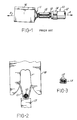
- Figure 1 is a plan view of a conventional crimp-type terminal.
- Figure 2 is a diagrammatic view showing conventional tooling used in the crimping of a terminal.
- Figure 3 is a cross-sectional view showing a conventional terminal after crimping.
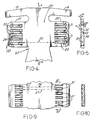
- Figure 4 is a partial bottom view showing a flat blank according to the present invention.
- Figure 5 is a side view of the blank shown in Figure 4.
- Figure 6 is a cross-sectional view of a terminal according to the present invention prior to crimping.
- Figure 7 is a plan view of a crimped terminal according to the present invention.
- Figure 8 is a cross-sectional view of the terminal of Figure 7 after crimping, taken along lines 8-8 of Figure 7.
- Figure 9 is a partial bottom view of an alternative embodiment of the conductor grips of the present invention.
- Figure 10 is a side cross-sectional view of the conductor grip along lines 10-10 of Figure 9.
- Multi conductor wire 10 is joined to a terminal 11.
- Multi conductor wire 10 includes an insulation covering 12 containing wire strands 13.
- Terminal 11 includes insulator grips 14 for gripping insulation 12 and conductor grips 15 for gripping strands 13.
- conductor grips 15 By crimping conductor grips 15 around wire strands 13, a cavity is formed which firmly retains wire strands 13 providing electrical continuity with terminal 11.
- Terminal 11 further includes connection means such as a box-type connector 16 for interconnecting with the mating terminal such as a blade terminal of an electrical device or another connection wire.
- connection means such as a box-type connector 16 for interconnecting with the mating terminal such as a blade terminal of an electrical device or another connection wire.
- Insulator grip 14 and conductor grips 15 grasp multi conductor wire 10 as a result of crimping.
- multi conductor wire strands 13 are laid within terminal 11 and the two are then placed on an anvil 17 with the conductor grips located below a punch 18.
- punch 18 and anvil 17 are quickly brought together.
- An upper curved surface within punch 18 crimps the grips of terminal 11 onto multi conductor wire strands 13.
- wire strands 13 are tightly retained within conductor grips 15 after crimping. Nevertheless, subsequent flexing of the multi conductor wire and other forces applied to conductor grips 15 can eventually result in a weakened connection and relative motion.
- FIG. 4 An improved connection is obtained using a terminal body 20 shown in Figure 4 which is formed from a flat, conductive metal blank.
- Insulator grips 14 extend from a central blank portion 25 substantially perpendicularly to longitudinal axis A of terminal body 20.
- a conductor grip 21 and a conductor grip 22 extend from central blank portion 25 substantially perpendicularly to longitudinal axis A.
- Figure 4 is a bottom view of terminal body 20, i.e., opposite from the side which receives the multi conductor wire.
- a pair of contact areas 23 and 24 come into contact after crimping.
- a plurality of grooves 30 are provided in conductor grip 21 and a plurality of grooves 31 are provided in conductor grip 22 such that grooves 30 and 31 pass through contact areas 23 and 24 in a direction perpendicular to longitudinal axis A.
- the ends of insulator grips 14 and conductor grips 21 and 22 are coined to facilitate crimping as is known in the art.
- Figure 5 is a side view of conductor grip 22.
- Grooves 31 have a depth "d" approximately equal to one-third the total width of conductor grip 22.
- Each groove 30 and 31 consists of a channel which may be stamped or otherwise formed in the terminal body.
- Each groove has a bottom surface 32 and side surfaces 33 sloping up to an intermediate surface 34. Bottom surfaces 32 and intermediate surfaces 34 all have a width "w" to facilitate interlocking of the grooves as will be described below.
- the terminal body of Figure 4 can be formed by any known process, such as by stamping. Respective grooves 30 and 31 are colinear but offset as shown by line 35. After formation of the flat terminal body, insulator grips 14 and conductor grips 21 and 22 are bent upward for the crimping process, for example, by rolling, such that grooves 30 and 31 are on the outside surface as shown in Figure 6. Interconnect means, such as socket 40 for a slip-on terminal, are formed by any suitable method. Any other interconnect means may alternatively be employed in the present invention, such as eyelets.
- Figure 7 shows a completed terminal after crimping.
- grooves 30 become interlocked with grooves 31, i.e., conductor grips 21 and 22 shift axially to permit the nesting of the grooves.
- the nested grooves provide mechanical locking which prevents movement of the conductor grips thereby maintaining the grasping force on conductors 13.
- conductors 13 are firmly held against the conductor body. The mechanical interlocking of grooves 30 and 31 insures that the firm contact is maintained over time.
- Figure 9 shows an alternative embodiment wherein grooves 31' are offset from grooves 30. As shown by lines 36 and 37, the respective grooves are interleaved when the grooves are first formed in the terminal body. Once again, the grooves are comprised of channels that may be stamped or otherwise formed in the terminal body. In this embodiment, grooves 31' do not extend all the way to the coined ends of conductor grips 21 and 22, thereby reducing wear on the surfaces of the crimping tools (i.e., punch) that would otherwise be caused by the groove edges at the coined ends.
- the crimping tools i.e., punch
Landscapes
- Connections Effected By Soldering, Adhesion, Or Permanent Deformation (AREA)
- Multi-Conductor Connections (AREA)
Claims (3)
- Crimp-Kabelschuh (11) zum Eincrimpen eines längs einer Achse ausgerichteten Litzenkabels (10) und zur Verbindung mit einem passenden Gegenschuh einer elektrischen Vorrichtung, wobei besagter Kabelschuh einen Kabelschuhkörper (20) aufweist, mit:dadurch gekennzeichnet, daßeinem flachen Stanzteil mit einem mittleren Stanzteilabschnitt (25);einer Isolatorklemme (14), die sich vom einen Ende des besagten mittleren Stanzteilabschnittes (25) aus im wesentlichen senkrecht zu besagter Achse erstreckt, zwecks Festklemmen eines isolierten Abschnittes des besagten Litzenkabels;Verbindermitteln (40), welche am anderen Ende des besagten mittleren Stanzteilabschnittes angeformt sind, zur Verbindung mit besagtem passendem Gegenschuh; und miteinem Paar Leiterklemmen (21, 22), welche sich von besagtem mittlerem Stanzteilabschnitt (25) aus zwischen besagter Isolatorklemme (14) und besagten Verbindermitteln und im wesentlichen senkrecht zu besagter Achse erstrecken, wobei besagte Leiterklemmen je eine Oberseite aufweisen, die nach dem Crimpen mit einem abisolierten Abschnitt des besagten Litzenkabels in Kontakt steht, wobei besagte Leiterklemmen auch je eine Unterseite haben, die beim Crimpen in entsprechenden Kontaktbereichen (23, 24) zur Anlage an der anderen Unterseite kommt;besagte Leiterklemmen (21, 22) in besagten Kontaktbereichen (23, 24) derselben Verriegelungsnuten (30, 31) aufweisen, die beim Crimpen miteinander in Eingriff treten, um so die Bewegung der besagten Leiterklemmen entlang besagter Achse nach dem Crimpen zu verringern, wobei besagte Verriegelungsnuten (30, 31) im wesentlichen senkrecht zu besagter Achse liegen und jeweils Nuten (30, 31) auf einer der besagten Leiterklemmen vor dem Crimpen den Gegennuten auf der anderen der besagten Leiterklemmen gegenüber versetzt sind.
- Kabelschuh nach Anspruch 1, worin besagte Nuten (30, 31) von Kanälen gebildet werden, die in besagte Leiterklemmen (21, 22) eingeformt sind.
- Elektrisches Verbindersystem mit einem isolierten Litzenkabel (10) mit einer Achse und mit einem abisolierten Ende, und mit einem Crimp-Kabelschuh (11) nach Anspruch 1 oder Anspruch 2, der so aufgecrimpt ist, daß er besagtes Litzenkabel festklemmt, wobei seine Isolatorklemme (14) die Kabelisolation (12) einklemmt, und wobei seine Leiterklemmen (21, 22) so gecrimpt sind, daß sie den abisolierten Abschnitt des besagten Kabels mit ihrer jeweiligen Oberseite einklemmen, und daß ihre jeweiligen Unterseiten in Eingriff miteinander stehen und ihre jeweiligen Nuten (30, 31) ineinander verriegelt sind.
Applications Claiming Priority (2)
| Application Number | Priority Date | Filing Date | Title |
|---|---|---|---|
| US4308593A | 1993-04-05 | 1993-04-05 | |
| US43085 | 1993-04-05 |
Publications (2)
| Publication Number | Publication Date |
|---|---|
| EP0619623A1 EP0619623A1 (de) | 1994-10-12 |
| EP0619623B1 true EP0619623B1 (de) | 1998-07-08 |
Family
ID=21925423
Family Applications (1)
| Application Number | Title | Priority Date | Filing Date |
|---|---|---|---|
| EP94301832A Expired - Lifetime EP0619623B1 (de) | 1993-04-05 | 1994-03-15 | Verpresste Leiterklemme |
Country Status (5)
| Country | Link |
|---|---|
| US (1) | US5425662A (de) |
| EP (1) | EP0619623B1 (de) |
| JP (1) | JP3429357B2 (de) |
| CA (1) | CA2120470A1 (de) |
| DE (1) | DE69411431T2 (de) |
Families Citing this family (8)
| Publication number | Priority date | Publication date | Assignee | Title |
|---|---|---|---|---|
| DE19549174A1 (de) * | 1995-10-28 | 1997-07-03 | Bosch Gmbh Robert | Kontaktelement mit Crimpabschnitt |
| DE102004043774B4 (de) * | 2004-09-10 | 2006-09-28 | Schulte-Elektrotechnik Gmbh & Co. Kg | Kontakthülse für den Anschluss wahlweise einer oder zweier Litzenleitungen |
| DE102006045567A1 (de) * | 2006-09-25 | 2008-04-24 | Tyco Electronics Amp Gmbh | Crimpstabilisierung |
| JP5362296B2 (ja) * | 2008-09-03 | 2013-12-11 | 矢崎総業株式会社 | 端子金具 |
| US8052492B2 (en) * | 2008-11-13 | 2011-11-08 | Delphi Technologies, Inc. | Multi-level electrical terminal crimp |
| JP5650381B2 (ja) * | 2009-04-07 | 2015-01-07 | 矢崎総業株式会社 | 圧着端子 |
| JP5464744B2 (ja) * | 2010-03-12 | 2014-04-09 | 日本航空電子工業株式会社 | コンタクト |
| JP2023521922A (ja) * | 2020-04-20 | 2023-05-25 | タイコエレクトロニクス フランス エスアーエス | 圧着端子 |
Family Cites Families (14)
| Publication number | Priority date | Publication date | Assignee | Title |
|---|---|---|---|---|
| US2821011A (en) * | 1952-03-25 | 1958-01-28 | Thomas A Sanders | Method for compression splicing of wires |
| NL111930C (de) * | 1956-08-16 | |||
| US2992404A (en) * | 1957-03-14 | 1961-07-11 | Berg Quentin | Electrical disconnect |
| US3137925A (en) * | 1959-05-29 | 1964-06-23 | Amp Inc | Method of splicing insulated conductors |
| GB954618A (en) * | 1961-12-06 | 1964-04-08 | Amp Inc | Electrical connection |
| US3387080A (en) * | 1966-07-25 | 1968-06-04 | Burndy Corp | Splice connector with locking insert |
| US3761872A (en) * | 1972-01-20 | 1973-09-25 | Thomas & Betts Corp | Brazed seam ferrule |
| US3735331A (en) * | 1972-04-19 | 1973-05-22 | Ark Les Switch Corp | Electrical connector |
| US3889048A (en) * | 1972-10-04 | 1975-06-10 | Erico Prod Inc | Electrical connector and clip therefor having barbs to ensure proper preassembly |
| US3990143A (en) * | 1974-06-21 | 1976-11-09 | Amp Incorporated | Method for terminating an electrical wire in an open barrel terminal |
| US4165148A (en) * | 1978-07-19 | 1979-08-21 | Square D Company | Compressible electrical connector with positive mechanical lock |
| GB2041794A (en) * | 1979-02-20 | 1980-09-17 | Bicc Burndy Ltd | Improvements in or relating to ferrules |
| US4692122A (en) * | 1986-10-06 | 1987-09-08 | Minnesota Mining And Manufacturing Company | Electrical terminal |
| US4815200A (en) * | 1987-11-30 | 1989-03-28 | Yazaki Corporation | Method for improving accuracy of connections to electrical terminal |
-
1994
- 1994-03-15 EP EP94301832A patent/EP0619623B1/de not_active Expired - Lifetime
- 1994-03-15 DE DE69411431T patent/DE69411431T2/de not_active Expired - Fee Related
- 1994-03-29 CA CA002120470A patent/CA2120470A1/en not_active Abandoned
- 1994-04-04 JP JP06625794A patent/JP3429357B2/ja not_active Expired - Fee Related
- 1994-09-26 US US08/312,494 patent/US5425662A/en not_active Expired - Fee Related
Also Published As
| Publication number | Publication date |
|---|---|
| DE69411431D1 (de) | 1998-08-13 |
| EP0619623A1 (de) | 1994-10-12 |
| JPH076800A (ja) | 1995-01-10 |
| JP3429357B2 (ja) | 2003-07-22 |
| DE69411431T2 (de) | 1998-11-05 |
| CA2120470A1 (en) | 1994-10-06 |
| US5425662A (en) | 1995-06-20 |
Similar Documents
| Publication | Publication Date | Title |
|---|---|---|
| KR950004365B1 (ko) | 전기접촉부재 | |
| US6749457B2 (en) | Crimp terminal | |
| AU737947B2 (en) | Improved two-piece male pin terminal connector | |
| US2600012A (en) | Electrical connector | |
| EP0499140B1 (de) | Vollständig schliessbarer H-förmiger Verbinder | |
| US2680235A (en) | Electrical connector | |
| EP0944130A2 (de) | Quetschverbindung | |
| EP1503453B1 (de) | H-förmiger Abzweigquetschverbinder | |
| US5338233A (en) | Structure for electrically connecting a terminal and a wire | |
| US5897394A (en) | Conductor connection terminal and method of connection | |
| US4921442A (en) | Housing for flat power cable connector | |
| EP0619623B1 (de) | Verpresste Leiterklemme | |
| US4867700A (en) | Wave crimp for flat power cable termination | |
| US5415015A (en) | Electrical terminal crimping tool | |
| EP0649186B1 (de) | Elektrische Anschlussklemme zum Aufpressen an einen Leiter | |
| JPH05198320A (ja) | 楔形コネクタ | |
| US4938713A (en) | Electrical terminal for wave crimp termination of flat power cable | |
| WO1986001941A1 (en) | Electrical connector for stranded wires | |
| JPH0572053U (ja) | ワイヤ圧着端子 | |
| EP0102156B1 (de) | Anschlusselement mit Isolationsverschiebung für einen elektrischen Verbinder und Umgebungsabdichtungsmittel dafür | |
| JP3523074B2 (ja) | 圧接端子 | |
| US4565001A (en) | Method of making crimp connect terminals | |
| KR940003483B1 (ko) | 평면형 전기케이블용 전환어댑터 및 그 케이블의 종단방법 | |
| JP2594055Y2 (ja) | 圧接ジョイントコネクタ | |
| US6296512B1 (en) | Press-connecting terminal |
Legal Events
| Date | Code | Title | Description |
|---|---|---|---|
| PUAI | Public reference made under article 153(3) epc to a published international application that has entered the european phase |
Free format text: ORIGINAL CODE: 0009012 |
|
| AK | Designated contracting states |
Kind code of ref document: A1 Designated state(s): DE FR GB |
|
| K1C1 | Correction of patent application (title page) published |
Effective date: 19941012 |
|
| 17P | Request for examination filed |
Effective date: 19950302 |
|
| 17Q | First examination report despatched |
Effective date: 19960301 |
|
| GRAG | Despatch of communication of intention to grant |
Free format text: ORIGINAL CODE: EPIDOS AGRA |
|
| GRAG | Despatch of communication of intention to grant |
Free format text: ORIGINAL CODE: EPIDOS AGRA |
|
| GRAH | Despatch of communication of intention to grant a patent |
Free format text: ORIGINAL CODE: EPIDOS IGRA |
|
| GRAH | Despatch of communication of intention to grant a patent |
Free format text: ORIGINAL CODE: EPIDOS IGRA |
|
| GRAA | (expected) grant |
Free format text: ORIGINAL CODE: 0009210 |
|
| AK | Designated contracting states |
Kind code of ref document: B1 Designated state(s): DE FR GB |
|
| PG25 | Lapsed in a contracting state [announced via postgrant information from national office to epo] |
Ref country code: FR Free format text: LAPSE BECAUSE OF FAILURE TO SUBMIT A TRANSLATION OF THE DESCRIPTION OR TO PAY THE FEE WITHIN THE PRESCRIBED TIME-LIMIT Effective date: 19980708 |
|
| RAP1 | Party data changed (applicant data changed or rights of an application transferred) |
Owner name: FORD FRANCE S. A. Owner name: FORD-WERKE AKTIENGESELLSCHAFT Owner name: FORD MOTOR COMPANY LIMITED |
|
| REF | Corresponds to: |
Ref document number: 69411431 Country of ref document: DE Date of ref document: 19980813 |
|
| EN | Fr: translation not filed | ||
| REG | Reference to a national code |
Ref country code: GB Ref legal event code: 746 Effective date: 19990216 |
|
| PLBE | No opposition filed within time limit |
Free format text: ORIGINAL CODE: 0009261 |
|
| STAA | Information on the status of an ep patent application or granted ep patent |
Free format text: STATUS: NO OPPOSITION FILED WITHIN TIME LIMIT |
|
| 26N | No opposition filed | ||
| REG | Reference to a national code |
Ref country code: GB Ref legal event code: IF02 |
|
| PGFP | Annual fee paid to national office [announced via postgrant information from national office to epo] |
Ref country code: GB Payment date: 20040205 Year of fee payment: 11 |
|
| PGFP | Annual fee paid to national office [announced via postgrant information from national office to epo] |
Ref country code: DE Payment date: 20040331 Year of fee payment: 11 |
|
| PG25 | Lapsed in a contracting state [announced via postgrant information from national office to epo] |
Ref country code: GB Free format text: LAPSE BECAUSE OF NON-PAYMENT OF DUE FEES Effective date: 20050315 |
|
| PG25 | Lapsed in a contracting state [announced via postgrant information from national office to epo] |
Ref country code: DE Free format text: LAPSE BECAUSE OF NON-PAYMENT OF DUE FEES Effective date: 20051001 |
|
| GBPC | Gb: european patent ceased through non-payment of renewal fee |
Effective date: 20050315 |