EP0619264B1 - Anordnung zum Ankuppeln eines Seiles einer Hebevorrichtung an ein Fertigteil - Google Patents
Anordnung zum Ankuppeln eines Seiles einer Hebevorrichtung an ein Fertigteil Download PDFInfo
- Publication number
- EP0619264B1 EP0619264B1 EP94104937A EP94104937A EP0619264B1 EP 0619264 B1 EP0619264 B1 EP 0619264B1 EP 94104937 A EP94104937 A EP 94104937A EP 94104937 A EP94104937 A EP 94104937A EP 0619264 B1 EP0619264 B1 EP 0619264B1
- Authority
- EP
- European Patent Office
- Prior art keywords
- cable
- arrangement according
- plate
- finished part
- section
- Prior art date
- Legal status (The legal status is an assumption and is not a legal conclusion. Google has not performed a legal analysis and makes no representation as to the accuracy of the status listed.)
- Expired - Lifetime
Links
- 230000008878 coupling Effects 0.000 title description 3
- 238000010168 coupling process Methods 0.000 title description 3
- 238000005859 coupling reaction Methods 0.000 title description 3
- 239000011178 precast concrete Substances 0.000 claims abstract description 6
- 239000004567 concrete Substances 0.000 abstract description 9
- 238000005452 bending Methods 0.000 description 11
- 230000006978 adaptation Effects 0.000 description 1
- 230000001419 dependent effect Effects 0.000 description 1
- 230000002349 favourable effect Effects 0.000 description 1
- 239000000463 material Substances 0.000 description 1
- 239000007787 solid Substances 0.000 description 1
Images



Classifications
-
- B—PERFORMING OPERATIONS; TRANSPORTING
- B66—HOISTING; LIFTING; HAULING
- B66C—CRANES; LOAD-ENGAGING ELEMENTS OR DEVICES FOR CRANES, CAPSTANS, WINCHES, OR TACKLES
- B66C1/00—Load-engaging elements or devices attached to lifting or lowering gear of cranes or adapted for connection therewith for transmitting lifting forces to articles or groups of articles
- B66C1/10—Load-engaging elements or devices attached to lifting or lowering gear of cranes or adapted for connection therewith for transmitting lifting forces to articles or groups of articles by mechanical means
- B66C1/12—Slings comprising chains, wires, ropes, or bands; Nets
-
- B—PERFORMING OPERATIONS; TRANSPORTING
- B66—HOISTING; LIFTING; HAULING
- B66C—CRANES; LOAD-ENGAGING ELEMENTS OR DEVICES FOR CRANES, CAPSTANS, WINCHES, OR TACKLES
- B66C1/00—Load-engaging elements or devices attached to lifting or lowering gear of cranes or adapted for connection therewith for transmitting lifting forces to articles or groups of articles
- B66C1/10—Load-engaging elements or devices attached to lifting or lowering gear of cranes or adapted for connection therewith for transmitting lifting forces to articles or groups of articles by mechanical means
- B66C1/62—Load-engaging elements or devices attached to lifting or lowering gear of cranes or adapted for connection therewith for transmitting lifting forces to articles or groups of articles by mechanical means comprising article-engaging members of a shape complementary to that of the articles to be handled
- B66C1/66—Load-engaging elements or devices attached to lifting or lowering gear of cranes or adapted for connection therewith for transmitting lifting forces to articles or groups of articles by mechanical means comprising article-engaging members of a shape complementary to that of the articles to be handled for engaging holes, recesses, or abutments on articles specially provided for facilitating handling thereof
- B66C1/666—Load-engaging elements or devices attached to lifting or lowering gear of cranes or adapted for connection therewith for transmitting lifting forces to articles or groups of articles by mechanical means comprising article-engaging members of a shape complementary to that of the articles to be handled for engaging holes, recesses, or abutments on articles specially provided for facilitating handling thereof for connection to anchor inserts embedded in concrete structures
-
- E—FIXED CONSTRUCTIONS
- E04—BUILDING
- E04G—SCAFFOLDING; FORMS; SHUTTERING; BUILDING IMPLEMENTS OR AIDS, OR THEIR USE; HANDLING BUILDING MATERIALS ON THE SITE; REPAIRING, BREAKING-UP OR OTHER WORK ON EXISTING BUILDINGS
- E04G21/00—Preparing, conveying, or working-up building materials or building elements in situ; Other devices or measures for constructional work
- E04G21/14—Conveying or assembling building elements
- E04G21/142—Means in or on the elements for connecting same to handling apparatus
-
- F—MECHANICAL ENGINEERING; LIGHTING; HEATING; WEAPONS; BLASTING
- F16—ENGINEERING ELEMENTS AND UNITS; GENERAL MEASURES FOR PRODUCING AND MAINTAINING EFFECTIVE FUNCTIONING OF MACHINES OR INSTALLATIONS; THERMAL INSULATION IN GENERAL
- F16G—BELTS, CABLES, OR ROPES, PREDOMINANTLY USED FOR DRIVING PURPOSES; CHAINS; FITTINGS PREDOMINANTLY USED THEREFOR
- F16G11/00—Means for fastening cables or ropes to one another or to other objects; Caps or sleeves for fixing on cables or ropes
- F16G11/04—Means for fastening cables or ropes to one another or to other objects; Caps or sleeves for fixing on cables or ropes with wedging action, e.g. friction clamps
- F16G11/044—Means for fastening cables or ropes to one another or to other objects; Caps or sleeves for fixing on cables or ropes with wedging action, e.g. friction clamps friction clamps deforming the cable, wire, rope or cord
- F16G11/048—Means for fastening cables or ropes to one another or to other objects; Caps or sleeves for fixing on cables or ropes with wedging action, e.g. friction clamps friction clamps deforming the cable, wire, rope or cord by moving a surface into the cable
-
- F—MECHANICAL ENGINEERING; LIGHTING; HEATING; WEAPONS; BLASTING
- F16—ENGINEERING ELEMENTS AND UNITS; GENERAL MEASURES FOR PRODUCING AND MAINTAINING EFFECTIVE FUNCTIONING OF MACHINES OR INSTALLATIONS; THERMAL INSULATION IN GENERAL
- F16G—BELTS, CABLES, OR ROPES, PREDOMINANTLY USED FOR DRIVING PURPOSES; CHAINS; FITTINGS PREDOMINANTLY USED THEREFOR
- F16G11/00—Means for fastening cables or ropes to one another or to other objects; Caps or sleeves for fixing on cables or ropes
- F16G11/06—Means for fastening cables or ropes to one another or to other objects; Caps or sleeves for fixing on cables or ropes with laterally-arranged screws
Definitions
- the invention relates to an arrangement for coupling a rope of a lifting device to a prefabricated part to be lifted or transported, in particular a prefabricated concrete part, according to the features of the preamble of claim 1.
- a known arrangement of this type (EP-A 0 161 652, DE-A-3 204 930) consists of an eyebolt which can be screwed into the precast concrete element and has an annular element which can be rotated relative to the threaded bolt screwed into the precast concrete element. At the outer end of the threaded bolt there is a holding member which supports the ring element. As a result of the rotatability of the ring element, this adapts to the direction of pull in the case of inclined pulls without the threaded bolt twisting in the finished part. As a result, excessive stresses caused by inclined pulls are largely avoided.
- the threaded bolt which cannot be rotated in the finished part, acts as a tie rod and is screwed into a sleeve concreted into the finished part, above which a support plate is provided which is formed in one piece with the threaded bolt.
- the 360 ° rotating eyebolt has one Above the threaded bolt extending transverse opening into which a part of the lifting device, for example an intermediate member in the form of a solid ring or a rope loop, engages.
- a disadvantage of this known embodiment is that the point of application of the lifting force in the case of an oblique pull lies at a relatively large distance from the surface of the finished part to be moved, so that in the case of an oblique and transverse pull, parts of the device, such as, in particular, the eyebolt, the threaded bolt and the threaded sleeve, considerable bending forces are exposed, which do not exclude the risk of kinking of the threaded sleeve or the tie rod in the event of transverse loading.
- the known device must accordingly be oversized accordingly for safety reasons.
- the invention has for its object to provide an arrangement of the generic type while avoiding the disadvantages of the known device, in which the stresses on bending, in particular the tie rod screwed into the cast-in threaded sleeve is optimally low at diagonal and transverse pulls and designed so is that the forces occurring when lifting the load have the smallest possible distance from the surface of the load to be lifted, and a point-like attack of the lifting force on the device which is dependent on the direction of pull is avoided.
- the actual receptacle for the lifting rope or an intermediate member of the lifting device i.e. the receptacle for the rope guide
- the tie rod i.e. the receptacle for the rope guide
- the receptacle for the cable guide is formed, for example, by a flat lower surface so that it can rest directly on the surface of the load, that is to say on the finished part surface, and the lifting rope is approximately parallel and in about an arcuate, preferably circular section of 180 ° is carried out in the immediate vicinity of the surface of the finished part, especially in the case of lifting forces which act parallel or slightly obliquely to the finished part surface, the tie rod and threaded sleeve are subjected to minimal bending stress, the load-bearing capacity of the sleeve and the device itself being considerably improved.
- the receptacle is designed, for example, as a plate-like plate, in which part of its circumference, preferably of 180 °, is designed as a section for a cable guide, in such a way that the cable is guided in this section, a sufficient result is obtained Large supporting surface of the device on the surface of the finished part, which means that bending moments that occur can be absorbed by the threaded sleeve in the finished part, the tie rod and by the supporting force on the finished part surface.
- the recording can also be used as a semi-oval plate a section for the cable guide or in a similar form. The bending capacity of the threaded sleeve or the tie rod therefore need not be fully exploited.
- the cable guide section of approximately 180 ° is advantageously formed on the circumference of the plate and lies centrally to a hole provided in the plate for the passage of the tie rod.
- the rope can be guided in the immediate vicinity of the surface of the finished part in a preferably semicircular arc around the circumference of the plate, which can itself be approximately semicircular.
- This cable guide on the end face of the receptacle designed as a plate allows the smallest possible distance between the cable and the finished part surface.
- the mounting plate can be made comparatively low, since it is only stressed by greatly reduced tensile and bending forces.
- a very advantageous further embodiment is obtained if the plate-shaped receptacle with its section for guiding the rope for its deflection from the direction parallel to the surface of the finished part in an upward outer pulling direction is assigned corresponding deflection means.
- corresponding deflection surfaces can advantageously be provided on the plate-shaped receptacle with its section for the cable guide at the two end regions of the cable guide section.
- these upward deflecting surfaces are arranged at the ends of a web, which preferably is approximately diagonal to the cable guide section 7 and above the plate and is integrally formed therewith.
- a perfect guidance of the rope is achieved, in particular in the case of an upward pull, in which the rope, in addition to its horizontal looping of the plate, is guided upwards in a predeterminable arc as a result of the predetermined, precisely defined deflecting surfaces, without the risk of being too strong Curvature or even the kinking of the rope.
- These deflecting surfaces are advantageously formed by the ends of the crosspiece, which project beyond the end regions of the cable guide section on both sides to such an extent that the cable is in perfect and complete contact in the region of these deflecting points.
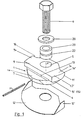
- FIG. 1 shows the arrangement for coupling a rope 10 (FIG. 2) to a lifting device as a whole together with tie rod 6, a threaded bolt which is screwed into a threaded sleeve 19 (FIGS. 2 and 3) cast into the prefabricated part 2 .
- the tie rod 6 passes through a bore 5 receptacle 1 for guiding the rope.
- this receptacle is designed as a plate-shaped plate 1, which consists of a lower plate part 1 a and an upper web 9.
- intermediate rings can be between the receptacle 1 and the tie rod 6 as required 20 and / or adapters 23 may be provided for adaptation to different sizes of the tie rod 6.
- the tie rod 6 required in each case can be adapted to the same size of the threaded sleeve 19 embedded in concrete, as is shown in FIG. 12 with four different tie rod sizes.
- Fig. 1 With 12 in Fig. 1 is a lower cover of the flat base 4 of the plate-shaped receptacle 1, which is also penetrated by the tie rod 6.
- the receptacle 1 for guiding the cable 10 which is designed in a simple manner as a plate, is supported on the surface 2 'of the prefabricated part 2 by the tie rod 6 and is rotatably mounted through 360 ° such that it can adjust itself to the corresponding direction of pull of the cable.
- the receptacle 1, which is designed as a plate is designed for direct bearing on the surface 2 'of the finished part 2, in such a way that the section 7, which is attached to the receptacle 1, preferably on its circumference, is at least approximately parallel with the attached rope 10 and lies directly next to or above the surface 2 'of the finished part.
- the base surface 4 of the receptacle designed as a plate 1 is a flat surface which, in the assembled state with the cover 12 interposed, lies directly on the finished part surface 2 'and parallel to it. Perpendicular to this flat base 4 is the bore 5, which penetrates the plate 1 and receives the tie rod 6.
- the rope guide section 7 can be provided with a concavely curved contact surface for the rope according to the curvature and thickness of the rope.
- the lower cover 12 has upright lateral guide surfaces 12 'which can also extend over the front area of the cable guide section 7 in order to hold the cable securely, in particular when the device is being assembled or disassembled.
- the receptacle 1 As a result of the design of the receptacle 1 as a flat, 360 ° rotatable plate with a cable guide section 7 on its circumference, which lies directly on the finished surface 2 ', the cable is guided directly on the concrete surface 2' and parallel to it, so that Practically no bending stresses act on the tie rod 6 and the threaded sleeve 19, which considerably improves the load-bearing capacity of the threaded sleeve and the receptacle 1 itself, especially since the tensile forces acting in the semicircular section of the rope 10 are applied to the semicircular rope guide section 7 with a comparatively low surface pressure.
- the plate 1 is therefore advantageously subjected to compressive forces in an advantageous manner and can accordingly be designed comparatively simply and optimally, in particular in a way that saves material and weight.
- these diametrically opposed, upward deflecting surfaces 11, 11 ' are arranged at the ends of the web 9 lying diagonally to the cable guide section 7.
- This web 9 is located on the top of the plate 1 and is formed in one piece with it, so that the plate 1 and thus the receptacle itself is additionally reinforced and forms a stable device part which is massive against compressive forces.
- the web 9 is also designed such that it projects beyond the plate 1 at the mutually opposite end regions 7a of the cable guide section 7, the projecting undersides of the web 9 each forming boundary surfaces 15, 15 'which run parallel to the concrete surface 2' and which extend into the upward direction pass over curved deflection surfaces 11, 11 '.
- An essential feature lies in the fact that the centers of the deflecting surfaces 11, 11 'which lead upward in the shape of a circular arc are offset with respect to the axis 5' of the bore 5 in such a way that the additional tensile and bending forces on the threaded sleeve 19 even under tensile and oblique loading and the tie rod 6 can be kept optimally low.
- a tunnel-like recess 17 is provided on the plate 1 for the cable, in which the cable guide section 7 is located.
- This tunnel-like recess 17 surrounds the rope in such a way that it is guided in a form-fitting manner and is preferably held in such a way that it cannot become detached from the device even when the device is being installed or removed.
- the tunnel-like recess 17 is also designed so that it can support the plate 1 when tipping forces occur on the concrete surface 2 '.
- the tunnel-like recess 17 is brought down to the flat base 4 of the plate 1 and is formed in the lower region as a support surface 18.
- the cable is completely surrounded except for its underside by the plate 1, whereby the special design of the front underside of the plate as a support surface 18 provides a favorable support for the plate on the finished part surface 2 '.
- This tunnel-like encirclement of the cable guide advantageously increases the lever arm of the supporting force in the area of the concrete surface.
- the plate 1 can also be made oval. 5 and 6 it is shown that the front part 17 'of the plate 1 delimiting the tunnel-like recess 17 has an oval projection projecting from the circular shape has through which the actual support surface 18 is enlarged. Despite the tunnel-like recess 17, the rope itself can be exchanged without any problems and is captively connected to the device. At the same time, it is prevented that the rope can lose its end position within the rope guide 7.
- the receptacle 1 in the form of a plate for the cable guide can be produced together with the web 9 with its deflecting surfaces 11, 11 'and the boundary surfaces 15, 15' as a whole, including the tunnel-like recess, as a cast part or forged part.
- the offset of the centers 24 of the upward deflecting surfaces 11, 11 ' is designed so that it is optimal for all directions of force. This offset depends on the rope diameter and the force application angles; its optimal absolute size can be determined in a simple manner, for example empirically. It is essential that, as a result of this offset, the additional tensile and bending stress of the tie rod 6 and the cast-in sleeve 19 is minimized in any direction of pull.
- the cable deflection through the guide 7 practically directly on the concrete surface causes in transverse pull that the plate and the tie rod are minimally stressed. If the tensile force acts parallel to the concrete surface, the effective lever arm only corresponds to half the rope diameter.
- an additional bore 13 is provided in the plate 1 at an angle to the axis 5 'of the bore 5, which serves to receive a locking pin 14.
- This locking pin 14 engages in an annular recess 22 of one of the adapters 23 which are used depending on the diameter of the tie rod 6 used (FIG. 12).
Landscapes
- Engineering & Computer Science (AREA)
- Mechanical Engineering (AREA)
- General Engineering & Computer Science (AREA)
- Architecture (AREA)
- Civil Engineering (AREA)
- Structural Engineering (AREA)
- Load-Engaging Elements For Cranes (AREA)
- Laying Of Electric Cables Or Lines Outside (AREA)
- Conveying And Assembling Of Building Elements In Situ (AREA)
- Types And Forms Of Lifts (AREA)
- Lift-Guide Devices, And Elevator Ropes And Cables (AREA)
Description
- Die Erfindung betrifft eine Anordnung zum Ankuppeln eines Seiles einer Hebevorrichtung an ein anzuhebendes oder zu transportierendes Fertigteil, insbesondere Betonfertigteil, gemäß den Merkmalen des Gattungsbegriffes des Anspruches 1.
- Eine bekannte Anordnung dieser Art (EP-A 0 161 652, DE-A-3 204 930) besteht aus einer Ringschraube, die sich in den Betonfertigteil einschrauben läßt und ein Ringelement besitzt, das gegenüber dem in den Betonfertigteil eingeschraubten Gewindebolzen verdrehbar ist. Am äußeren Ende des Gewindebolzens befindet sich ein Halteglied, das das Ringelement abstützt. Infolge der Verdrehbarkeit des Ringelementes paßt sich dieses bei Schrägzügen der Zugrichtung an, ohne daß sich der Gewindebolzen im Fertigteil verdreht. Dadurch werden Überbeanspruchungen durch Schrägzüge weitgehend vermieden. Der unverdrehbar im Fertigteil sitzende Gewindebolzen wirkt als Zuganker und ist in eine in das Fertigteil einbetonierte Hülse eingeschraubt, oberhalb der eine Stützplatte vorgesehen ist, die mit dem Gewindebolzen einstückig ausgebildet ist. Die um 360° drehbare Ringschraube hat eine oberhalb des Gewindebolzens sich erstreckende, quer liegende Öffnung, in die ein Teil der Hebevorrichtung , beispielsweise ein Zwischenglied in der Form eines massiven Ringes oder einer Seilschlaufe, eingreift.
- Nachteilig bei dieser bekannten Ausführung ist, daß der Angriffspunkt der Hebekraft bei Schrägzug mit relativ großem Abstand von der Oberfläche des fortzubewegenden Fertigteiles liegt, so daß bei Schräg- und Querzug Teile der Vorrichtung, wie insbesondere die Ringschraube, der Gewindebolzen und die Gewindehülse, erheblichen Biegekräften ausgesetzt sind, die bei Querbeanspruchung sogar die Gefahr der Abknickung der Gewindehülse bzw. des Zugankers nicht ausschließen. Die bekannte Vorrichtung muß demgemäß aus Sicherheitsgründen entsprechend überdimensioniert werden. Weiter ist nachteilig, daß das ovale, nach Art eines Handgriffes ausgebildete Ringelement mit seiner gegenüber der Plattenoberfläche sehr hoch liegenden, ovalen Aufnahmeöffnung für das Zwischenglied bzw. eine Seilschlaufe selbst je nach Angriffspunkt der Hebekraft unterschiedlichen Zug-, Biege- und Querkräften ausgesetzt ist und demgemäß entsprechend dimensioniert werden muß.
- Der Erfindung liegt die Aufgabe zugrunde, eine Anordnung der gattungsgemäßen Art unter Vermeidung der Nachteile der bekannten Vorrichtung zu schaffen, bei der die Beanspruchungen auf Biegung, insbesondere des in die einbetonierte Gewindehülse eingeschraubten Zugankers bei Schräg- und und Querzügen optimal gering ist und die so gestaltet ist, daß die beim Heben der Last auftretenden Kräfte einen kleinstmöglichen Abstand von der Oberfläche der anzuhebenden Last haben, sowie ein von der Zugrichtung abhängiger, punktförmiger Angriff der Hebekraft an der Vorrichtung vermieden ist.
- Diese Aufgabe wird bei einer Anordnung mit den Merkmalen des Gattungsbegriffes des Anspruches 1 durch die Merkmale seines kennzeichnenden Teiles gelöst.
- Dadurch, daß bei der erfindungsgemäßen Lösung die eigentliche Aufnahme für das Hebeseil oder ein Zwischenglied der Hebevorrichtung, also die Aufnahme zur Seilführung, infolge Abstützung durch den Zuganker drehbar abgestützt ist, kann sie sich in bekannter Weise um 360° drehen und sich somit auf die jeweilige Zugrichtung einstellen. Da jedoch die Aufnahme für die Seilführung beispielsweise durch eine plane Unterfläche so ausgebildet ist, daß sie unmittelbar auf der Oberfläche der Last, also auf der Fertigteiloberfläche, aufliegen kann, und das Hebeseil um einen bogenförmigen, vorzugsweise kreisförmigen Abschnitt von 180° annähernd parallel und in unmittelbarer Nähe neben der Oberfläche des Fertigteils geführt ist, werden insbesondere bei Hebekräften, die parallel oder geringfügig schräg zur Fertigteiloberfläche wirken, Zuganker und Gewindehülse minimal auf Biegung beansprucht, wobei die Trägfähigkeit der Hülse und der Vorrichtung selbst erheblich verbessert werden.
- Wenn in weiterer Ausbildung der Erfindung die Aufnahme als beispielsweise tellerartige Platte ausgeführt ist, bei der ein Teil ihres Umfanges, vorzugsweise von 180°, als Abschnitt für eine Seilführung ausgebildet ist, derart, daß das Seil in diesem Abschnitt geführt ist, ergibt sich eine ausreichend große Absützfläche der Vorrichtung an der Fertigteiloberfläche, wodurch auftretende Biegemomente über die Gewindehülse im Fertigteil, den Zuganker und durch die Abstützkraft an der Fertigteiloberfläche aufgenommen werden können. Die Aufnahme kann auch als halbovale Platte mit einem Abschnitt für die Seilführung oder in einer ähnlichen Form ausgeführt sein. Die Biegetragfähigkeit der Gewindehülse bzw. des Zugankers braucht somit nicht voll ausgenutzt zu werden.
- Vorteilhaft ist der Seilführungsabschnitt von etwa 180° am Umfang der Platte ausgebildet und liegt zentrisch zu einer in der Platte vorgesehenen Bohrung für den Durchtritt des Zugankers. Hierdurch kann das Seil in unmittelbarer Nähe der Oberfläche des Fertigteiles in einem vorzugsweise halbkreisförmigen Bogen um dem Umfang der Platte, die selbst etwa halbkreisförmig ausgebildet sein kann, geführt werden. Diese Seilführung an der Stirnseite der als Platte ausgebildeten Aufnahme ermöglicht einen kleinstmöglichen Abstand zwischen Seil und Fertigteiloberfläche. Außerdem kann die Aufnahmeplatte vergleichsweise niedrig ausgeführt werden, da sie nur von stark reduzierten Zug- und Biegekräften beansprucht wird.
- Eine sehr vorteilhafte weitere Ausgestaltung ergibt sich, wenn der plattenförmigen Aufnahme mit ihrem Abschnitt für die Führung des Seiles zu dessen Umlenkung von der Richtung parallel zur Oberfläche des Fertigteiles in eine nach oben gerichtete äußere Zugrichtung entsprechende Umlenkmittel zugeordnet sind. Hierzu können vorteilhaft an der plattenförmigen Aufnahme mit ihrem Abschnitt für die Seilführung an den beiden Endbereichen des Seilführungsabschnittes entsprechende Umlenkflächen vorgesehen sein. Hierdurch wird das etwa parallel und mit minimalem Abstand von der Fertigteiloberfläche geführte Seil in Richtung zur Hebevorrichtung, also nach oben hin, umgelenkt. Diese nach oben gerichteten Umlenkflächen sind bei einer einfachen Ausführungsform der Anordnung an den Enden eines Steges angeordnet, der vorzugsweise annähernd diagonal zum Seilführungsabschnitt 7 und oberhalb der Platte liegt und einstückig mit dieser ausgebildet ist. Hierdurch wird eine einwandfreie Führung des Seiles, insbesondere bei aufwärts gerichtetem Zug, erreicht, bei der das Seil außer seiner horizontalen Umschlingung der Platte infolge der vorgegebenen, genau definierten Umlenkflächen in einem vorbestimmbaren Bogen nach oben geführt wird, ohne daß dabei die Gefahr einer zu starken Krümmung oder gar die der Abknickung des Seiles besteht. Vorteilhaft werden diese Umlenkflächen durch die Enden des Quersteges gebildet, die die Endbereiche des Seilführungsabschnittes beidseitig so weit überragen, daß eine einwandfreie und vollständige Anlage des Seiles im Bereich dieser Umlenkstellen gegeben ist.
- Die Erfindung wird nachstehend anhand der Zeichnungen näher erläutert. Diese zeigen:
- Fig. 1
- eine Explosivdarstellung einer Ausführungsform der erfindungsgemäßen Anordnung,
- Fig. 2
- in Seitenansicht, teilweise geschnitten, die Anordnung nach Fig. 1, die mittels Zugankers auf der Oberfläche einer Betonfertigplatte befestigt ist,
- Fig. 3
- dieselbe Anordnung, jedoch in Ansicht des Pfeiles III,
- Fig. 4
- eine Draufsicht auf die Anordnung nach Fig. 2,
- Fig. 5
- eine abgewandelte Ausführung der als Platte ausgebildeten Aufnahme in Ansicht von unten,
- Fig. 6
- eine Ansicht von oben auf die plattenförmige Aufnahme der Fig. 5,
- Fig. 7
- einen Schnitt nach Linie VII-VII in Fig. 5,
- Fig. 8
- einen Schnitt nach Linie VIII-VIII in Fig. 6,
- Fig. 9
- zeigt eine etwas abgeänderte Ausführung der Platte in Draufsicht,
- Fig. 10
- eine Ansicht in Richtung des Pfeiles X in Fig. 9,
- Fig. 11
- eine Ansicht in Richtung Pfeil XI in Fig. 9 und
- Fig. 12
- verschiedene Ausführungen des Zugankers für verschiedene Laststufen für ein und dieselbe Größe der Gewindehülse im Betonfertigteil sowie eine Ausführung des mit den Paßstücken zusammenwirkenden Sicherungsstiftes.
- Die Explosivdarstellung nach Fig. 1 zeigt die Anordnung zum Ankuppeln eines Seiles 10 (Fig. 2) an eine Hebevorrichtung als ganzes samt Zuganker 6, einem Gewindebolzen, der in eine in das Fertigteil 2 eingegossene Gewindehülse 19 (Fig. 2 und 3) eingeschraubt wird. Der Zuganker 6 durchgreift eine Bohrung 5 Aufnahme 1 für die Führung des Seiles. Diese Aufnahme ist, wie aus den Fig. 1 bis 10 hervorgeht, als tellerförmige Platte 1 ausgebildet, die aus einem unteren Plattenteil 1a und einem oberen Steg 9 besteht. Wie aus Fig. 1 ersichtlich, können zwischen der Aufnahme 1 und dem Zuganker 6 nach Bedarf Zwischenringe 20 und/oder Paßstücke 23 zwecks Anpassung an verschiedene Größen des Zugankers 6 vorgesehen sein. Dadurch kann bei verschiedenen Lastfällen der jeweils erforderliche Zuganker 6 auf ein und dieselbe Größe der einbetonierten Gewindehülse 19 angepaßt werden, wie dies in Fig. 12 an vier unterschiedlichen Zugankergrößen dargestellt ist.
- Mit 12 ist in Fig. 1 eine untere Abdeckung der plan ausgebildeten Grundfläche 4 der plattenförmigen Aufnahme 1 bezeichnet, die gleichfalls vom Zuganker 6 durchdrungen wird.
- Die in einfacher Weise als Platte ausgebildete Aufnahme 1 zur Führung des Seiles 10 ist auf der Oberfläche 2' des Fertigteiles 2 durch den Zuganker 6 abgestützt und um 360° drehbar gelagert, derart, daß sie sich jeweils auf die entsprechende Zugrichtung des Seiles einstellen kann.
- Nach der Erfindung ist die als Platte ausgebildete Aufnahme 1 zur direkten Auflage auf der Oberfläche 2' des Fertigteiles 2 ausgebildet, und zwar derart, daß der an der Aufnahme 1, vorzugsweise an deren Umfang, angebrachte Abschnitt 7 mit dem anliegenden Seil 10 wenigstens annähernd parallel und unmittelbar neben bzw. oberhalb der Oberfläche 2' des Fertigteiles liegt. Hierzu ist die Grundfläche 4 der als Platte 1 ausgebildeten Aufnahme eine plane Fläche, die im montierten Zustand unter Zwischenlage der Abdeckung 12 unmittelbar auf der Fertigteiloberfläche 2' und parallel zu dieser liegt. Senkrecht zu dieser planen Grundfläche 4 befindet sich die Bohrung 5, die die Platte 1 durchdringt und den Zuganker 6 aufnimmt.
- Zentrisch zur Bohrung 5 ist am Umfang der Platte 1 der Seilführungsabschnitt 7 vorgesehen, der über einen Winkel von 180° reicht. Um diesen Abschnitt 7 ist das Seil 10 geführt; es liegt somit an der Stirnseite der tellerartigen Platte 1 im montierten Zustand an, wie dies aus den Fig. 2 bis 4 ersichtlich ist.
- Um eine sichere Führung des Seiles 10 in diesem Bereich zu erhalten, kann der Seilführungsabschnitt 7 entsprechend der Krümmung und Dicke des Seiles mit einer konkav gekrümmten Anlagefläche für das Seil versehen sein. Die untere Abdeckung 12 hat hochkant gestellte seitliche Führungsflächen 12', die auch bis über den vorderen Bereich des Seilführungsabschnittes 7 verlaufen können, um das Seil, insbesondere bei der Montage oder Demontage der Vorrichtung, sicher zu haltern.
- Infolge der Ausbildung der Aufnahme 1 als flache, um 360° drehbare, mit einem Seilführungsabschnitt 7 an ihrem Umfang versehene Platte, die unmittelbar auf der Fertigteiloberfläche 2' aufliegt, wird das Seil direkt an der Betonoberfläche 2' und parallel zu dieser geführt, so daß praktisch keine Biegebeanspruchungen auf den Zuganker 6 und die Gewindehülse 19 einwirken, wodurch die Tragfähigkeit der Gewindehülse und der Aufnahme 1 selbst erheblich verbessert werden, zumal die in dem halbkreisförmig geführten Abschnitt des Seiles 10 wirkenden Zugkräfte mit vergleichsweise niedriger Flächenpressung an dem halbkreisförmigen Seilführungsabschnitt 7 anliegen. Die Platte 1 ist daher im wesentlichen in vorteilhafter Weise Druckkräften ausgesetzt und kann demgemäß vergleichsweise einfach gestaltet und optimal, insbesondere material- und gewichtsparend dimensioniert werden.
- Um bei allen möglichen Belastungsrichtungen die wirksamen Kräfte zu minimieren und zu hohe Beanspruchungen des Seiles selbst, insbesondere dessen Abknickung bei schräg aufwärtsgerichtetem Zug zu vermeiden, ist an den beiden Endbereichen 7a des Seilführungsabschnittes 7 an der Platte 1 je eine Umlenkfläche 11 bzw. 11' vorhanden, die das Seil 10 von der Fertigteiloberfläche 2' weg nach oben in Richtung zur Hebevorrichtung führt.
- In den dargestellten Ausführungsbeispielen sind diese diametral einander gegenüberliegenden, nach oben weisenden Umlenkflächen 11, 11' an den Enden des diagonal zum Seilführungsabschnitt 7 liegenden Steges 9 angeordnet. Dieser Steg 9 befindet sich auf der Oberseite der Platte 1 und ist einstückig mit dieser ausgebildet, so daß die Platte 1 und damit die Aufnahme selbst zusätzlich verstärkt wird und einen stabilen, gegen Druckkräfte massiven Vorrichtungsteil bildet. Der Steg 9 ist ferner so ausgebildet, daß er die Platte 1 an den einander gegenüberliegenden Endbereichen 7a des Seilführungsabschnittes 7 überragt, wobei jeweils die überstehenden Unterseiten des Steges 9 parallel zur Betonoberfläche 2' verlaufende Begrenzungsflächen 15, 15' bilden, die in die nach oben gebogen verlaufenden Umlenkflächen 11, 11' übergehen. Ein wesentliches Merkmal liegt darin, daß die Zentren der annähernd kreisbogenförmig nach oben führenden Umlenkflächen 11, 11' gegenüber der Achse 5' der Bohrung 5 versetzt sind, derart, daß auch unter Zug- und Schrägbeanspruchung die zusätzlichen Zug- und Biegekräfte auf die Gewindehülse 19 und den Zuganker 6 optimal gering gehalten werden.
- Durch diesen Versatz der Umlenkflächen 11 und 11' und ihrer rückseitigen Abschlußkanten 16 bzw. 16' wird die Beanspruchung des Zugankers 6, insbesondere auf Zug und Biegung, und zwar für alle auftretenden Lastfälle in Lastrichtung optimal minimiert, wobei durch die Abrundung der im Bogen nach oben verlaufenden Umlenkflächen 11, 11' beim Anheben scharfe Abknickungen des Seiles vermieden werden. Zweckmäßig verlaufen die Abschlußkanten 16, 16' der Umlenkflächen 11, 11' parallel zu dem Durchmesser 7', der den Halbkreis des Seilführungsabschnittes 7 begrenzt.
- Bei der Ausführung nach den Fig. 5 bis 8 ist eine tunnelartige Ausnehmung 17 an der Platte 1 für das Seil vorgesehen, in der sich der Seilführungsabschnitt 7 befindet. Diese tunnelartige Ausnehmung 17 umschließt das Seil derart, daß es formschlüssig geführt und vorzugsweise derart gehaltert ist, daß es sich auch bei Montage oder Demontage der Vorrichtung nicht von dieser lösen kann.
- Die tunnelartige Ausnehmung 17 ist ferner so gestaltet, daß sie die Platte 1 bei auftretenden Kippkräften auf der Betonoberfläche 2' abzustützen vermag. Zu diesem Zweck ist die tunnelartige Ausnehmung 17 bis zur planen Grundfläche 4 der Platte 1 heruntergeführt und im unteren Bereich als Abstützfläche 18 ausgebildet. Auf diese Weise ist das Seil bis auf seine Unterseite von der Platte 1 vollständig umgeben, wobei durch die besondere Ausbildung der vorderen Unterseite der Platte als Abstützfläche 18 eine günstige Abstützung der Platte auf der Fertigteiloberfläche 2' erreicht wird. Durch diese tunnelartige Umfassung der Seilführung wird der Hebelarm der Abstützkraft im Bereich der Betonoberfläche vorteilhaft vergrößert.
- Zur Vergrößerung des Hebelarms der Abstützkraft kann die Platte 1 auch oval ausgeführt werden. In den Fig. 5 und 6 ist dargestellt, daß der der die tunnelartige Ausnehmung 17 begrenzende vordere Teil 17' der Platte 1 einen gegenüber der Kreisform vorspringenden ovalen Ansatz hat, durch welchen die eigentliche Abstützflache 18 vergrößert wird. Das Seil selbst kann trotz der tunnelartigen Ausnehmung 17 problemlos ausgewechselt werden und ist mit der Vorrichtung unverlierbar verbunden. Gleichzeitig wird verhindert, daß das Seil seine stirnseitige Lage innerhalb der Seilführung 7 verlieren kann.
- Die Aufnahme 1 in Form einer Platte für die Seilführung kann samt Steg 9 mit seinen Umlenkflächen 11, 11' und den Begrenzungsflächen 15, 15' als ganzes unter Einbeziehung der tunnelartigen Ausnehmung als Gußteil oder Schmiedeteil hergestellt werden.
- Der Versatz der Zentren 24 der nach oben führenden Umlenkflächen 11, 11' ist so ausgelegt, daß er für alle Kraftrichtungen optimal ist. Dieser Versatz ist abhängig vom Seildurchmesser und den Kraftangriffswinkeln; seine optimale absolute Größe kann in einfacher Weise, beispielsweise empirisch, ermittelt werden. Wesentlich ist, daß infolge dieses Versatzes bei jeder beliebigen Zugrichtung die zusätzliche Zug- und Biegebeanspruchung des Zugankers 6 und der eingegossenen Hülse 19 minimiert wird. Die Seilumlenkung durch die Führung 7 praktisch direkt an der Betonoberfläche bewirkt bei Querzug, daß die Platte und der Zuganker minimal beansprucht werden. Wirkt die Zugkraft parallel zur Betonoberfläche, entspricht der wirksame Hebelarm nur der Hälfte des Seildurchmessers.
- Wie die Fig. 1 und 9 bis 11 zeigen, ist in der Platte 1 winklig zur Achse 5' der Bohrung 5 eine zusätzliche Bohrung 13 vorgesehen, die zur Aufnahme eines Sicherungsstiftes 14 dient. Dieser Sicherungsstift 14 greift in eine ringförmige Ausnehmung 22 eines der Paßstücke 23 ein, die je nach Durchmesser des verwendeten Zugankers 6 eingesetzt werden (Fig. 12).
Claims (15)
- Anordnung zum Ankuppeln eines Seiles einer Hebevorrichtung an ein Fertigteil, insbesondere Betonfertigteil, mit einer Aufnahme für das Seil, die auf der Fertigteiloberfläche mit einem Zuganker abgestützt und drehbar gelagert ist,
dadurch gekennzeichnet, daß die Aufnahme (1) zur Auflage auf der Fertigteiloberfläche (2) ausgebildet ist und ein an der Aufnahme (1) befindlicher Abschnitt (7) für die Führung des Seiles (10) angeordnet ist, der wenigstens annähernd parallel zur Oberfläche (2') des Fertigteiles (2) und unmittelbar neben dieser vorgesehen ist. - Anordnung nach Anspruch 1,
dadurch gekennzeichnet, daß die Aufnahme (1) als Platte und der Abschnitt (7) zur Führung des Seiles (10) bogenförmig ausgebildet ist. - Anordnung nach einem der Ansprüche 1 oder 2,
dadurch gekennzeichnet, daß die Aufnahme (1) senkrecht zu ihrer planen Grundfläche (4) eine Bohrung (5) zur Aufnahme des Zugankers (6) aufweist. - Anordnung nach einem der Ansprüche 1 bis 3,
dadurch gekennzeichnet, daß der Seilführungsabschnitt (7) zentrisch zur Bohrung (5) am Umfang der Platte (1) vorgesehen ist und wenigstens annähernd über einen Winkel von 180° an der annähernd halbkreisförmigen oder halbovalen Platte ausgebildet ist. - Anordnung nach einem der Ansprüche 1 bis 4,
dadurch gekennzeichnet, daß versetzt zur Achse (5') der Bohrung (5) Mittel (11, 11') zur Umlenkung des Seiles (10) von der Richtung parallel zur Oberfläche(2') des Fertigteiles (2) nach oben in die äußere Zugrichtung vorgesehen sind. - Anordnung nach einem der Ansprüche 1 bis 5,
dadurch gekennzeichnet, daß die Platte (1) an den beiden Endbereichen (7a) des Seilführungsabschnittes (7) Umlenkflächen (11, 11') aufweist, derart, daß das Seil (10) von der Fertigteiloberfläche (2') weg nach oben in Richtung zur Hebevorrichtung geführt ist. - Anordnung nach einem der Ansprüche 1 bis 6,
dadurch gekennzeichnet, daß die nach oben gerichteten Umlenkflächen (11, 11') an den Enden eines über dem Seilführungsabschnitt (7) liegenden Steges (9) vorgesehen sind. - Anordnung nach Anspruch 7,
dadurch gekennzeichnet, daß der Steg (9) auf der Oberseite der Platte (1) angeordnet und mit dieser einstückig ausgebildet ist und die einander gegenüberliegenden Endbereiche (7a) des Seilführungsabschnittes (7) überragt, und daß ferner jeweils an der Unterseite der beiden überstehenden Teile des Steges (9) die nach oben abgebogenen Umlenkflächen (11, 11') sowie diesen vorgelagerte, die Seilführung sichernde Begrenzungsflächen (15, 15') vorgesehen sind. - Anordnung nach einem der Ansprüche 1 bis 8,
dadurch gekennzeichnet, daß die Zentren (24) der nach oben führenden Umlenkflächen (11, 11') gegenüber der Achse (5') der Bohrung (5) versetzt sind. - Anordnung nach Anspruch 9,
dadurch gekennzeichnet, daß die Abschlußkanten (16, 16') der Umlenkflächen (11, 11') parallel zu dem Durchmesser (7') liegen, der den Halbkreis des Seilführungsabschnittes (7) begrenzt. - Anordnung nach einem der Ansprüche 1 bis 10,
dadurch gekennzeichnet, daß der Seilführungsabschnitt (7) als tunnelartige Ausnehmung (17) der Platte (1) ausgebildet ist, derart, daß das Seil (10) in der Ausnehmung (17) formschlüssig gehalten ist. - Anordnung nach Anspruch 11,
dadurch gekennzeichnet, daß die tunnelartige Ausnehmung (17) bis zu der Grundfläche (4) der plattenförmigen Aufnahme (1) heruntergeführt ist und am unteren Ende als Abstützfläche (18) ausgebildet ist. - Anordnung nach einem der Ansprüche 1 bis 12,
dadurch gekennzeichnet, daß zwischen der Platte (1) und der Fertigteiloberfläche (2') eine vorzugsweise dünnwandige Abdeckung (12) vorgesehen ist. - Anordnung nach einem der Ansprüche 1 bis 13,
dadurch gekennzeichnet, daß die Platte (1) im Winkel zur Bohrung (5) eine zusätzliche Bohrung (13) zur Aufnahme eines Sicherungsstiftes (14) aufweist. - Anordnung nach einem der Ansprüche 1 bis 14,
dadurch gekennzeichnet, daß für ein und dieselbe Gewindehülse (19) Zuganker unterschiedlichen Durchmessers verwendbar sind, wobei Zuganker mit kleinerem Durchmesser mit entsprechenden Paßstücken (23) versehen sind und die Paßstücke eine ringförmige Ausnehmung (22) für einen Sicherungsstift (14) aufweisen.
Applications Claiming Priority (2)
| Application Number | Priority Date | Filing Date | Title |
|---|---|---|---|
| DE4311757A DE4311757A1 (de) | 1993-04-08 | 1993-04-08 | Vorrichtung zum Ankuppeln eines Seiles einer Hebevorrichtung an ein Fertigteil |
| DE4311757 | 1993-04-08 |
Publications (2)
| Publication Number | Publication Date |
|---|---|
| EP0619264A1 EP0619264A1 (de) | 1994-10-12 |
| EP0619264B1 true EP0619264B1 (de) | 1997-05-28 |
Family
ID=6485176
Family Applications (1)
| Application Number | Title | Priority Date | Filing Date |
|---|---|---|---|
| EP94104937A Expired - Lifetime EP0619264B1 (de) | 1993-04-08 | 1994-03-29 | Anordnung zum Ankuppeln eines Seiles einer Hebevorrichtung an ein Fertigteil |
Country Status (4)
| Country | Link |
|---|---|
| US (1) | US5560664A (de) |
| EP (1) | EP0619264B1 (de) |
| AT (1) | ATE153632T1 (de) |
| DE (2) | DE4311757A1 (de) |
Families Citing this family (7)
| Publication number | Priority date | Publication date | Assignee | Title |
|---|---|---|---|---|
| US6267422B1 (en) * | 1999-06-23 | 2001-07-31 | Cbc Industries, Inc. | Side mount hoist ring |
| RU2285774C2 (ru) * | 2003-12-10 | 2006-10-20 | Государственное образовательное учреждение высшего профессионального образования "Южно-Российский государственный технический университет (Новочеркасский политехнический институт)" ГОУ ВПО ЮРГТУ (НПИ) | Бетонное изделие и устройство для его строповки |
| US7984534B2 (en) * | 2007-01-04 | 2011-07-26 | Duggan Daniel C | Cable restraint clip |
| CN101857165A (zh) * | 2010-06-11 | 2010-10-13 | 林成富 | 增加负荷式铝合金压制钢丝绳索具 |
| DE102013002734B4 (de) * | 2013-02-19 | 2015-03-05 | Firep Rebar Technology Gmbh | Ankerkopf für einen Zuganker und Ankermutter für einen Ankerkopf eines Zugankers |
| ES2862138T3 (es) | 2014-10-22 | 2021-10-07 | Erico Int Corp | Conjunto de riostra y elemento de fijación para rigidizar una barra de suspensión |
| US12435831B2 (en) * | 2022-01-18 | 2025-10-07 | Anchor Ring Solutions, Llc | Construction anchor apparatus, system and methodology |
Family Cites Families (14)
| Publication number | Priority date | Publication date | Assignee | Title |
|---|---|---|---|---|
| US3297293A (en) * | 1965-01-13 | 1967-01-10 | American Drill Bushing Company | Fastening device |
| US3371951A (en) * | 1966-12-19 | 1968-03-05 | John G. Bryant | Material handling fittings |
| US3492033A (en) * | 1968-09-18 | 1970-01-27 | Charles R Mueller & Sons Inc | Clevis assembly |
| US3628820A (en) * | 1969-12-18 | 1971-12-21 | Leland F Blatt | Swivel-type hoist ring |
| US3905633A (en) * | 1974-09-30 | 1975-09-16 | Caterpillar Tractor Co | Swivel mounted lifting eye for engines |
| GB2040872A (en) * | 1979-01-03 | 1980-09-03 | Oceanic Contractors | Sling engagement boss |
| DE3204930C2 (de) * | 1982-02-12 | 1986-06-12 | Gebr. Eickhoff Maschinenfabrik U. Eisengiesserei Mbh, 4630 Bochum | Vorrichtung zum Transportieren oder Aufhängen von Maschinenteilen |
| DE8307694U1 (de) * | 1983-03-16 | 1983-08-11 | Siemens AG, 1000 Berlin und 8000 München | Schraubbare anhebevorrichtung |
| DE3329374C2 (de) * | 1983-08-13 | 1985-06-13 | Ernst Dr.-Ing. 4300 Essen Haeussler | Hilfsvorrichtung für die Manipulation eines Stahlbetonfertigteils |
| DE8414736U1 (de) * | 1984-05-15 | 1984-08-16 | Pfeifer Seil- Und Hebetechnik Gmbh & Co, 8940 Memmingen | Ringschraube |
| EP0208028A1 (de) * | 1985-07-08 | 1987-01-14 | Pmb Systems Engineering Limited | Hebevorrichtung und Prüfeinrichtung |
| US5125861A (en) * | 1990-08-20 | 1992-06-30 | Freeman Lewis G | Lifting eyebolt assembly |
| US5286130A (en) * | 1992-12-22 | 1994-02-15 | Mueller Charles R | Clevis assembly |
| GB2411997B (en) * | 2004-03-10 | 2007-08-29 | Advanced Analysis And Integrat | Methods and apparatus for product authentication |
-
1993
- 1993-04-08 DE DE4311757A patent/DE4311757A1/de not_active Withdrawn
-
1994
- 1994-03-29 AT AT94104937T patent/ATE153632T1/de not_active IP Right Cessation
- 1994-03-29 DE DE59402875T patent/DE59402875D1/de not_active Expired - Lifetime
- 1994-03-29 EP EP94104937A patent/EP0619264B1/de not_active Expired - Lifetime
- 1994-04-08 US US08/225,720 patent/US5560664A/en not_active Expired - Lifetime
Also Published As
| Publication number | Publication date |
|---|---|
| DE59402875D1 (de) | 1997-07-03 |
| US5560664A (en) | 1996-10-01 |
| EP0619264A1 (de) | 1994-10-12 |
| DE4311757A1 (de) | 1994-10-13 |
| ATE153632T1 (de) | 1997-06-15 |
Similar Documents
| Publication | Publication Date | Title |
|---|---|---|
| DE2755280A1 (de) | Schwenkbare schaekelverbindung | |
| DE3942383C2 (de) | Spannvorrichtung | |
| DE10100993C2 (de) | Einrichtung zum Verstellen der Länge eines als Endlosschlinge ausgebildeten Anschlagmittels und Vorrichtung zum Heben von Lasten | |
| DE3642248A1 (de) | Kranausleger mit in verschiedenen winkeln daran anbringbarer verlaengerung | |
| DE69115406T2 (de) | Mobiles Gerät zum Wiegen einer Ladung | |
| DE19802187A1 (de) | Vorrichtung zum Abspannen einer Superlift-Einrichtung eines Teleskopkranes | |
| DE20015556U1 (de) | In Verbindung mit Gliederketten einsetzbares Bauteil | |
| EP0619264A1 (de) | Vorrichtung zum Ankuppeln eines Seiles einer Hebevorrichtung an ein Fertigteil | |
| DE69331062T2 (de) | Vorhängeschloss | |
| EP0381941B1 (de) | Ständer für einen Bandförderer | |
| DE2623898C3 (de) | Aufhängevorrichtung für langgestreckte Gegenstände | |
| EP2408706B1 (de) | Anschlagelement und kombination aus einem anschlagelement und einem befestigungsmittel | |
| DE2826541A1 (de) | Lasthaken | |
| DD224012A1 (de) | Wippwerk fuer auslegerkrane, insbesondere mit teleskopausleger | |
| AT502333A1 (de) | Kippbares metallurgisches gefäss | |
| EP2174904B1 (de) | Vorrichtung zum Anschlagen einer Kette in einem Flurförderzeug | |
| EP0066567A2 (de) | Auf einem Lastfahrzeug anbringbarer Ladekran | |
| DE3734919A1 (de) | Ausleger mit horizontaler seilabspannung | |
| DE2833815A1 (de) | Klammerschrauben-verbindungselement | |
| DE2302315A1 (de) | Mast fuer hochspannungsleitung mit mindestens einem ausleger | |
| EP0040289A1 (de) | Spanneinrichtung für einen Senkrechtförderer, insbesondere ein Becherwerk | |
| EP0121767B1 (de) | Schraubbare Anhebevorrichtung | |
| DE29810777U1 (de) | Kettenförderer | |
| AT410437B (de) | Maststützeinrichtung | |
| DE1756375C3 (de) | Derrick-Kran, insbesondere für Schiffe |
Legal Events
| Date | Code | Title | Description |
|---|---|---|---|
| PUAI | Public reference made under article 153(3) epc to a published international application that has entered the european phase |
Free format text: ORIGINAL CODE: 0009012 |
|
| AK | Designated contracting states |
Kind code of ref document: A1 Designated state(s): AT BE CH DE DK ES FR GB LI NL SE |
|
| 17P | Request for examination filed |
Effective date: 19940929 |
|
| GRAG | Despatch of communication of intention to grant |
Free format text: ORIGINAL CODE: EPIDOS AGRA |
|
| 17Q | First examination report despatched |
Effective date: 19960722 |
|
| GRAH | Despatch of communication of intention to grant a patent |
Free format text: ORIGINAL CODE: EPIDOS IGRA |
|
| GRAH | Despatch of communication of intention to grant a patent |
Free format text: ORIGINAL CODE: EPIDOS IGRA |
|
| RAP1 | Party data changed (applicant data changed or rights of an application transferred) |
Owner name: HALFEN GMBH & CO. KOMMANDITGESELLSCHAFT |
|
| GRAA | (expected) grant |
Free format text: ORIGINAL CODE: 0009210 |
|
| AK | Designated contracting states |
Kind code of ref document: B1 Designated state(s): AT BE CH DE DK ES FR GB LI NL SE |
|
| PG25 | Lapsed in a contracting state [announced via postgrant information from national office to epo] |
Ref country code: ES Free format text: THE PATENT HAS BEEN ANNULLED BY A DECISION OF A NATIONAL AUTHORITY Effective date: 19970528 Ref country code: DK Effective date: 19970528 |
|
| REF | Corresponds to: |
Ref document number: 153632 Country of ref document: AT Date of ref document: 19970615 Kind code of ref document: T |
|
| REG | Reference to a national code |
Ref country code: CH Ref legal event code: EP |
|
| GBT | Gb: translation of ep patent filed (gb section 77(6)(a)/1977) |
Effective date: 19970528 |
|
| ET | Fr: translation filed | ||
| REF | Corresponds to: |
Ref document number: 59402875 Country of ref document: DE Date of ref document: 19970703 |
|
| PG25 | Lapsed in a contracting state [announced via postgrant information from national office to epo] |
Ref country code: SE Effective date: 19970828 |
|
| PG25 | Lapsed in a contracting state [announced via postgrant information from national office to epo] |
Ref country code: AT Free format text: LAPSE BECAUSE OF NON-PAYMENT OF DUE FEES Effective date: 19980329 |
|
| PG25 | Lapsed in a contracting state [announced via postgrant information from national office to epo] |
Ref country code: LI Free format text: LAPSE BECAUSE OF NON-PAYMENT OF DUE FEES Effective date: 19980331 Ref country code: CH Free format text: LAPSE BECAUSE OF NON-PAYMENT OF DUE FEES Effective date: 19980331 Ref country code: BE Free format text: LAPSE BECAUSE OF NON-PAYMENT OF DUE FEES Effective date: 19980331 |
|
| PLBE | No opposition filed within time limit |
Free format text: ORIGINAL CODE: 0009261 |
|
| STAA | Information on the status of an ep patent application or granted ep patent |
Free format text: STATUS: NO OPPOSITION FILED WITHIN TIME LIMIT |
|
| 26N | No opposition filed | ||
| BERE | Be: lapsed |
Owner name: HALFEN G.M.B.H. & CO. K.G. Effective date: 19980331 |
|
| REG | Reference to a national code |
Ref country code: CH Ref legal event code: PL |
|
| REG | Reference to a national code |
Ref country code: GB Ref legal event code: IF02 |
|
| REG | Reference to a national code |
Ref country code: GB Ref legal event code: 732E |
|
| REG | Reference to a national code |
Ref country code: FR Ref legal event code: TP |
|
| NLT1 | Nl: modifications of names registered in virtue of documents presented to the patent office pursuant to art. 16 a, paragraph 1 |
Owner name: HALFEN GMBH |
|
| PGFP | Annual fee paid to national office [announced via postgrant information from national office to epo] |
Ref country code: GB Payment date: 20130321 Year of fee payment: 20 Ref country code: DE Payment date: 20130321 Year of fee payment: 20 Ref country code: FR Payment date: 20130408 Year of fee payment: 20 |
|
| PGFP | Annual fee paid to national office [announced via postgrant information from national office to epo] |
Ref country code: NL Payment date: 20130320 Year of fee payment: 20 |
|
| REG | Reference to a national code |
Ref country code: NL Ref legal event code: V4 Effective date: 20140329 Ref country code: DE Ref legal event code: R071 Ref document number: 59402875 Country of ref document: DE |
|
| REG | Reference to a national code |
Ref country code: GB Ref legal event code: PE20 Expiry date: 20140328 |
|
| PG25 | Lapsed in a contracting state [announced via postgrant information from national office to epo] |
Ref country code: GB Free format text: LAPSE BECAUSE OF EXPIRATION OF PROTECTION Effective date: 20140328 |
|
| PG25 | Lapsed in a contracting state [announced via postgrant information from national office to epo] |
Ref country code: DE Free format text: LAPSE BECAUSE OF EXPIRATION OF PROTECTION Effective date: 20140401 |