EP0618740A2 - Appareil de reproduction d'images tridimensionnelles - Google Patents
Appareil de reproduction d'images tridimensionnelles Download PDFInfo
- Publication number
- EP0618740A2 EP0618740A2 EP94400667A EP94400667A EP0618740A2 EP 0618740 A2 EP0618740 A2 EP 0618740A2 EP 94400667 A EP94400667 A EP 94400667A EP 94400667 A EP94400667 A EP 94400667A EP 0618740 A2 EP0618740 A2 EP 0618740A2
- Authority
- EP
- European Patent Office
- Prior art keywords
- images
- pixels
- printing
- image
- printed
- Prior art date
- Legal status (The legal status is an assumption and is not a legal conclusion. Google has not performed a legal analysis and makes no representation as to the accuracy of the status listed.)
- Ceased
Links
Images


Classifications
-
- G—PHYSICS
- G06—COMPUTING; CALCULATING OR COUNTING
- G06K—GRAPHICAL DATA READING; PRESENTATION OF DATA; RECORD CARRIERS; HANDLING RECORD CARRIERS
- G06K15/00—Arrangements for producing a permanent visual presentation of the output data, e.g. computer output printers
- G06K15/02—Arrangements for producing a permanent visual presentation of the output data, e.g. computer output printers using printers
- G06K15/12—Arrangements for producing a permanent visual presentation of the output data, e.g. computer output printers using printers by photographic printing, e.g. by laser printers
-
- H—ELECTRICITY
- H04—ELECTRIC COMMUNICATION TECHNIQUE
- H04N—PICTORIAL COMMUNICATION, e.g. TELEVISION
- H04N1/00—Scanning, transmission or reproduction of documents or the like, e.g. facsimile transmission; Details thereof
- H04N1/21—Intermediate information storage
-
- H—ELECTRICITY
- H04—ELECTRIC COMMUNICATION TECHNIQUE
- H04N—PICTORIAL COMMUNICATION, e.g. TELEVISION
- H04N1/00—Scanning, transmission or reproduction of documents or the like, e.g. facsimile transmission; Details thereof
- H04N1/00127—Connection or combination of a still picture apparatus with another apparatus, e.g. for storage, processing or transmission of still picture signals or of information associated with a still picture
- H04N1/00132—Connection or combination of a still picture apparatus with another apparatus, e.g. for storage, processing or transmission of still picture signals or of information associated with a still picture in a digital photofinishing system, i.e. a system where digital photographic images undergo typical photofinishing processing, e.g. printing ordering
- H04N1/00185—Image output
- H04N1/00201—Creation of a lenticular or stereo hardcopy image
-
- H—ELECTRICITY
- H04—ELECTRIC COMMUNICATION TECHNIQUE
- H04N—PICTORIAL COMMUNICATION, e.g. TELEVISION
- H04N1/00—Scanning, transmission or reproduction of documents or the like, e.g. facsimile transmission; Details thereof
- H04N1/23—Reproducing arrangements
Definitions
- the present invention relates to an image output apparatus, and more particularly to an image output apparatus for outputting a three-dimensional image.
- a method known as the multi-view three-dimensional picture display method is given in U.S. Pat. No. 3895867 in which pictures are taken with a camera using a photographic film which will accept a plurality of images which are shifted with respect to each other only by the parallax in perspective between a pair of views.
- the negative imprinted on this film is then used to make a combined image by going from a plurality of points via this lenticular lens. This image is then printed. If this printed image is then viewed via the same lenticular lens, an image which appears to be three-dimensional can then be viewed without the aid of glasses.
- a method is put forward where an item such as a lenticular lens made up from a large number of rows of semi- cylindrical lenses is used. When a large number of images arranged along a first direction are then viewed, only one of these images is selected to be expanded from its compressed size for viewing so that a three-dimensional visual effect results.
- This kind of display method is put forward in, for example, in Television Association Magazine Vol. 45, No. 11, pp1472 to 1474 (1991) entitled 50-inch multi-vision three-dimensional television without glasses.
- n cameras are used to pick up images of the target (object) from different perspectives.
- n pixels will correspond to one pitch p (the width of the lens taken along the direction at right angles to the generating line for a single semi-cylindrical lens) of the lenticular lens, and just one of these n pixels will correspond to each of the n cameras.
- p the width of the lens taken along the direction at right angles to the generating line for a single semi-cylindrical lens
- just one of these n pixels will correspond to each of the n cameras.
- (n-1) of the frames taken by each camera can be discarded, i.e. (n-1) pixels are cancelled out.
- FIG. 11a is an outline cut-away view of one part of lenticular lens sheet 120 made up of an arrangement of lenticular lenses consisting of a plurality of semi-cylindrical lenses 101, 102, 103, ... placed on the front surface of a light diffusion type display board 110 for displaying, for example, n images to be described in the following.
- FIG. 11c shows each of the pixels and their rows for the images taken by the plurality of cameras (in the example in FIG. 11 there are four cameras, 131 to 134) i.e. pixels A11, A12, ... A36 for camera 131, pixels B11, B12, ...
- FIG. 11b shows the arrangement of each of the pixels for images displayed within a single pitch of each of the semi-cylindrical lenses as viewed from below (from the display board side) of the lenticular lens sheet 120 in FIG. 11a.
- the only pixels which are selected for displaying from within one pitch of the semi-cylindrical lens 101 are the column of A11, A21, A31, ... from the pixels coming from camera 131, the column of B12, B22, B31,...from the pixels coming from camera 132, the column of C13, C23, C33, ... from the pixels coming from camera 133 and the row of D14, D24, D34, ... from the pixels coming from camera 134. These are then displayed in rows at the display board 110 as is shown in FIG. 11b.
- the only pixels which are selected for displaying from within one pitch of the semi-cylindrical lens 102 are the column of A15, A25, A35, ...
- images from each of the plurality (four) of cameras 131 to 134 are now displayed at the display board 110 of the lenticular lens sheet 120. If these images displayed on the display board 110 are then viewed via each of the semi-cylindrical lenses 101, 102, 103, ... , it is possible to see different images for each of the different perspectives LA to LD. i.e. an image photographed by camera 131 can be viewed at perspective LA, an image photographed by camera 132 can be viewed at perspective LB, an image photographed by camera 133 can be viewed at perspective LC and an image photographed by camera 134 can be viewed at perspective LD.
- thinning out is carried out for each of the pixels when images from each of the cameras 131 to 134 are displayed at the display board 110.
- the image is enlarged in a direction which is at right angles to the direction of the generating lines for each of the semi-cylindrical lenses 101, 102, 103, ... shown in FIG. 11 which make up the lenticular lens.
- a lenticular lens sheet having these kinds of characteristics an image having a height to width ratio of 1:1 can be obtained as for a normal display apparatus.
- a three-dimensional display apparatus employing a method for structuring more detailed images where the pixels are arranged in rows is described in Laid-open publication Hei 3-97390.
- pixel data for n source images are gathered in 1/n parcels by cancelling out to get a source size image.
- cancelling out is carried out and n differing pixels are lined up every one pitch in the horizontal direction (i.e. in a direction perpendicular to that of the generating lines for the lenticular lens).
- the same pixels are then repeatedly lined up n times in the lengthwise direction of the lenticular lens (i.e. the direction of the generating lines) so as to give a method with an n x n image size.
- FIG. 12a is a cut-away outline of the surface of one part of the same lenticular lens sheet 120 as in FIG. 11a
- FIG. 12c in the same way as FIG. 11c, is a view of each of the pixels and rows for the images taken by, for example, the four cameras 131 to 134
- FIG. 12b shows the arrangement (i.e. the arrangement when viewed from the lower surface of the lenticular lens sheet 120) of each of the pixels to give an n x n image size.
- each of the pixels displayed from within one pitch p of the semi-cylindrical lens 101 are, as is shown in FIG. 12b, the pixel row A11, A21, A31, ... , the row B11, B21, B31, ... , the row C11, C21, C31, ... and the row D11, D21, D31, ... which have been selected from the pixels in FIG. 12c coming from the cameras 131 to 134.
- these pixels are repeated in groups of n (which in this case is 4) along the direction of the generating lines (i.e. the longitudinal direction) of the respective semi-cylindrical lenses. i.e.
- the pixels are repeatedly displayed n times along the longitudinal direction of the lenticular lenses so as to give an n x n image size.
- the image size becomes large when compared with that for normal display apparatus.
- the apparatus therefore has to be made large in order to display the whole of an image and the large volume of data is difficult to handle. It is also not possible to achieve a density which is high when compared with normal display apparatus.
- the image is also enlarged in a direction which is at right angles to the direction of the generating lines for the semi-cylindrical lenses so as to give the same resolution in the direction of the generating lines for the semi-cylindrical lenses and in the direction which is at right angles to the direction of the generating lines and this also causes deterioration in the picture quality.
- the present invention sets out to solve the problems encountered in the prior art, its object is to provide an image output apparatus which is capable of returning one image from a row of images in one direction to the size of the original source image when viewed via an item such as a lenticular lens in such a manner so as to make a picture display with little deterioration in picture quality possible.
- an image output apparatus for printing images, in which a plurality of images are superimposed and printed in one direction, and one of the plurality of images is displayed when being observed, comprising: an image synthesizing means for synthesizing the plurality of images; a print means for printing the synthesized images on one surface of a lenticular sheet having lenticular lenses on the other surface; a detection means for detecting a position of the lenticular sheet; and a control means for controlling the print means.
- the position of the lenticular sheet and/or an output of the print means are controlled on the basis of the detection result of the detection means, and pixels at the same position of the plurality images obtained by a plurality of image pickup devices are printed in correspondence with a plurality of unit lenses which form the lenticular lenses.
- the detection means may comprise: a projection portion for projecting a ray of light to the lenticular lenses; and an optical detection means for detecting an amount of transmissive and/or reflective light relative to the lenticular lenses whereby the position of the lenticular sheet may be detected on the basis of the amount of light detected by the optical detection portion.
- an image output apparatus for printing images by superimposition printing a plurality of images in a first direction in such a manner that one of these images is displayed through lenticular lenses when being observed, comprising: a printer for printing the images; and a controller for controlling the printer, wherein a large number of pixels are printed per unit length of the first direction by printing the pixels so as to be superimposed by making a feed for each pixel in the first direction smaller than the size of the pixel in the first direction while the plurality of pixels are being superimposition printed.
- an image output apparatus for printing images by superimposition printing a plurality of images in a first direction in such a manner that one of the images is displayed through lenticular lenses when being observed, comprising: a printer for printing the images; and a controller for controlling the printer, wherein a large number of pixels are printed per unit length of the first direction by shortening the length of the pixels in the first direction to make the pixels narrow, and reducing the feed for these pixels in the first direction by an amount corresponding to the extent to which the pixels were made narrow while the plurality of pixels are being superimposition printed.
- the pitch p corresponds to a pitch of the lenticular lenses.
- the feed s is changeable and printing is also possible at a different pitch p.
- an image printing apparatus for printing images by superimposition printing a plurality of images in a first direction in such a manner that one of the plurality of images is displayed through lenticular lenses when the images are observed, comprising: a printer for printing the images; and a controller for controlling the printer, wherein a large number of pixels are printed per unit length of the first direction, and the feed for each pixel is corrected and then printed when the enlargement rate of the image in the direction which is at right angles to the first direction is different to that for the image which has been displayed in the first direction while the plurality of pixels are being superimposition printed.
- the image output apparatus in the present invention by making the feed and size of each pixel in the first direction smaller so as to superimpose the pixels when printing while the plurality of images are being superimposition printed, or by narrowing the shape of the images in this first direction and then reducing the feed for each pixel by the portion by which each of the pixels have been narrowed, it is possible to make the number of pixels per unit length of this first direction large.
- the feed for each pixel is changed and the shape of the pixels is narrowed along the first direction so that a large number of pixels can be printed per unit length of this first direction.
- Correction (re-sizing) is therefore carried out on the feed for the pixels in this first direction before printing, which will remove distortions in the height-width ratio of the viewed image.
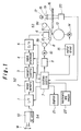
- n images are superimposition printed on, for example, a lenticular lens sheet 16 along a first direction of a lenticular lens. If these images are then viewed via the lenticular lens, an image which is selected from these n images is seen as having returned to the size of the original.
- this printing apparatus is made up of an image printer 53 for printing the images and a computer 52 for controlling the image printer 53. As is described below, while the plurality of images is being superimposition printed, the lengths of these pixels may be shortened in a first direction and printed so as these images are overlaid or superimposed.
- each of the pixels printed while the plurality of images are being superimposition printed may be flattened so as to become narrower and the length of the pixel in the first direction may therefore be reduced. This would mean that by reducing the unit length of the pixels in the first direction, the number of pixels may be increased.
- FIG. 2 is a perspective view of the structure in FIG. 1 being applied to an actual system.
- a print image which appears to be three-dimensional is printed directly onto the lenticular lens sheet described previously
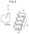
- FIG. 3 shows the single still camera 51 in the same figure each time it is shifted along the direction indicated by the arrow M.
- the image data recorded in the IC memory card 54 for the n times which images were taken is then read in by the system computer 52 in FIG. 2 (i.e. a main processor for example, which functions as the system control circuit 7 in FIG. 1). After this data which has been read in has been processed to give a picture output for outputting on the computer 52 (for example, the kind of rearrangement of the picture data described in the following), the image data are sent to the printer 53 for printing.
- This printer 53 may, for example, be a heat sensitivesublimation type image printer with a thermal line head.
- the algorithm for rearranging the image data in the computer 52 for this embodiment of the present invention is the same as the method described in Television Association Magazine Vol. 45, No. 11 entitled 50-inch multi-vision three-dimensional television not requiring glasses with the exception of the following point.
- the size of a pixel for printing for a single unit head is then txw.
- FIG. 4(a) shows the flat arrangement for each of the unit heads h in the line head H
- FIG. 4(b) shows each of the pixels g printed by the same line head H.
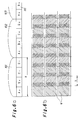
- FIG. 5(a) and FIG. 5(b) printing is carried out by superimposing images in the row direction (i.e. the direction at right angles to the generating lines) of the semi-cylindrical lenticular lens so that the number of pixels per unit length is increased (the resolving power is increased).
- FIG. 5(a) shows the flat arrangement for each of the unit heads h in the line head H
- FIG. 5(b) shows each of the pixels g printed by the same line head H.
- the superimposed printing of the image is then achieved by making the feed pitch s smaller than the width w of the unit head h (pixel size in the aforementioned first direction) and the head pitch q (s ⁇ w, s ⁇ q).
- a group of n pixels (image elements) can be repeatedly overlaid (multi-superimposed) within one pitch p between the semi-cylindrical shaped lenses 101, 102, 103, ... when printed.
- Printing according to this embodiment corresponding to the case shown in FIG. 11(a) and (b) and FIG. 12(a) and (b) is shown in FIG. 6 (a) and (b). Namely, as is shown in FIG. 6(b), by superimposing each of the pixels laid in the pitch p between each of the semi-cylindrical shaped lenses the resolution can be increased. Therefore, according to the printing apparatus for this embodiment, printing may be carried out without cancellation of the pixels which occurred in the aforementioned prior art or with reducing the amount of the cancellation.
- the feed for the lenticular lens sheet at the image printer 53 may be decided at the computer 52 by setting up means for measuring the pitch p between the lenticular lenses at the printer 53 or by transmitting data for the lenticular lens pitch p and the size w of the pixels in the first direction between the computer 52 and the image printer 53.
- n compressed square pixels are gathered from different perspectives by the electronic still camera source 51, they can be lined up within one pitch p of the lenticular lens for outputting.
- just the pixel within the one pitch for this particular direction will be selected from within the one pitch, and a picture will be displayed resembling that originally taken by the source.
- FIG. 9(a) to (d) a third embodiment is shown in FIG. 9(a) to (d) where the image resolution is improved without the occurrence of distortion by combining a method of correcting of the height to width radio of the image with the method described above.
- the feed pitch s for the line head is reduced in the way described above (or a flat head is used) and reducing is carried out (for example, 1/k times) in the first direction (i.e., the direction at right angles to the generating lines of the lens ).
- the pixels for this reduced image are then distributed in such a manner that underneath the lenticular lens there is a pixel for each pitch p of the semi- cylindrical shaped lens.
- this third embodiment for example, if the number of pixels is increased n/k times, printed so that the image is then enlarged by a lenticular lens, it is possible to correct (re-size) the height/width ratio of the image to be the same as that of the original image.
- correction was carried out on distortion which occurred when the image was sampled in a square grating manner and the feed pitch s was reduced.
- correction of distortion can be carried out by applying the same principles when the height/width ratio is not that of a square grating.
- image data stored in the IC card 54 for the electron still camera 51 is provided to the image data digital I/F circuit 1.
- This image data is sent to the image memory 2 via the I/F circuit 1.
- the image memory 2 keeps the image data which it receives until the latter part of the processing for the image data acquired previously has been carried out.
- the image data held in the image memory 2 is then read out by the memory controller 3.
- the readout at this time is composed of the images which were taken from n different perspectives. Their reading out is then controlled so as the pixels are arranged in rows with each row corresponding to each different perspective being arranged within one pitch p of the lenticular lens. Control is carried out during the readout so that the image data is read out in the necessary order for the scanning direction of the line head of the image printer 53 and the predetermined signal processing at the frontend signal processing circuit 4.
- Predetermined signal processing for example, color signal conversion (R,G, B to Y, M and C conversion) is then carried out by the signal processing circuit 4 on the image data provided via the memory controller 3.
- the output from the signal processing circuit 4 is then converted to an analog signal by the D/A converter 5 before being sent to the image printer 53.
- the data sent to the image printer 53 is then sent to the thermal head 6 of the sublimation method printer described previously.
- a lenticular lens sheet 16 is provided at the image printer 53.
- the side of the lenticular lens sheet 16 on which the image is to be printed (the display side) is set to face the side of the thermal heads 6 before this lenticular lens sheet 16 is sent to the platen roller 13 by a supply means which is not shown in the figure.
- the platen roller 13, the lenticular lens sheet 16, a ribbon 8 soaked in sublimation paint and the thermal heads 6 are positioned next to each other in that order.
- This ribbon 8 is supported on both sides of the thermal head 6 by guides 12, and is wound from the supply reel 9a onto the takeup reel 9b.
- the winding on of the ribbon 8 onto the take wheel is carried out by a motor 10 which is operated accordingto a drive signal sent from the drive circuit 11.
- the platen roller 13 is also driven by a platen motor 14 which is under the control of the motor driver 15. Accordingly, the thermal head 6 imparts a heat to the ribbon whereby a paint or pigment impregnated to the ribbon is thermally transferred directly to the lenticular sheet 16.
- This motor driver 15 is under the control of items such as a system control circuit 7 which may be, for example, a CPU (central processing unit) and is as such controlled so that the platen motor 14, i.e., the platen roller 13 is sent a distance equal to the feed pitch s for the lenticular lens sheet 16 in this embodiment described previously.
- a system control circuit 7 which may be, for example, a CPU (central processing unit) and is as such controlled so that the platen motor 14, i.e., the platen roller 13 is sent a distance equal to the feed pitch s for the lenticular lens sheet 16 in this embodiment described previously.
- the printer 53 is controlled according to the control sequence in FIG. 10 at the system control circuit 7.
- step S1 a list of the image data (data sampled at a height : width ratio of a : 1) which comes from the IC memory card 54 via the I/F circuit 1 is displayed as a whole, for example, on the display 21 of the computer 52 in FIG. 2. Then, n images are selected from the contents of the list for the memory card 54 using the keyboard and the mouse 22 so that a three-dimensional print can be made (images are selected for superimposition printing).
- step S3 data such as the pitch p for the lenticular lens sheet 16 currently being used, the permitted values for the feed pitch s, and the head pitch q is read out from the image printer 53 connected in the system.
- step S5 it is then determined whether the feed pitch s falls within the permitted limits or not. If the answer in step S5 is no, then the process proceeds to step S2, and if the answer is yes, the process proceeds to step S6.
- step S6 The re-sizing of the height is then carried out in step S6, i.e., the height is re-sized so that the height to width ratio of the sampling of the source image becomes q/p. Specifically, the number of pixels in the height direction is made to be a x p/q.
- Rows in the image are interchanged in step S7, and data is then outputted to the image printer 53 in step S8.
- the system control circuit 7 detects the lens pitch p of the semi-cylindrical lenses for the lenticular lens sheet 16, and then carries out the control of items such as the feed pitch s of the of the lenticular lens sheet 16 based on this detection signal.
- a light source 17, slit 18 lens 19 and a photosensor 20 are set up as the detecting means for detecting the positions of each of the semi-cylindrical lenses on the lenticular lens sheet 16.
- this light source 17 passes through the slit 18 so as to form a narrow light beam.
- This light beam is then made to be a parallel light beam by the lens 19 and is projected at the lenticular lens sheet 16.
- This projected light is then converged by each of the semi-cylindrical shaped lenses on the lenticular lens sheet 16 and is then inputted to the photosensor 20.
- the center of the photosensor 20 and the center of a semi-cylindrical shaped lens coincides, the amount of light inputted to the photosensor 20 becomes a maximum and the photosensor detection output is also large. In this way, the position of each of the semi-cylindrical lenses on the lenticular lens sheet can be detected.
- the feed for the lenticular lens sheet 16 is known by the system control circuit 7 so as to coincide with the position of each of the semi-cylindrical lenses.
- detection has been carried out using the light from the light source 17 which passes through the lenticular lens sheet 16, but the light which is reflected by the convex surfaces of each of the semi-cylindrical lenses on the lenticular lens sheet could also be used.
- the printing apparatus in this embodiment if the size of the feed for pixels in a first direction is reduced while a number of images are being superimposed and printed and these pixels are superimposed and printed, and if the shape of each of the pixel is made narrower in this first direction, the feed for each of the pixels in this first direction can be reduced by this narrowed amount.
- the number of pixels for each of the unit lengths of the pixels in this first direction can therefore be increased, and the resolution when viewing takes place in the direction for which the density of pixels is low in the enlarged image is increased.
- a printing apparatus can be realized which is versatile and is suitable for displaying directional images at a high resolution.
Applications Claiming Priority (2)
| Application Number | Priority Date | Filing Date | Title |
|---|---|---|---|
| JP69828/93 | 1993-03-29 | ||
| JP5069828A JPH06278318A (ja) | 1993-03-29 | 1993-03-29 | プリント装置 |
Publications (2)
| Publication Number | Publication Date |
|---|---|
| EP0618740A2 true EP0618740A2 (fr) | 1994-10-05 |
| EP0618740A3 EP0618740A3 (fr) | 1995-05-03 |
Family
ID=13414023
Family Applications (1)
| Application Number | Title | Priority Date | Filing Date |
|---|---|---|---|
| EP94400667A Ceased EP0618740A3 (fr) | 1993-03-29 | 1994-03-29 | Appareil de reproduction d'images tridimensionnelles. |
Country Status (4)
| Country | Link |
|---|---|
| US (1) | US5557413A (fr) |
| EP (1) | EP0618740A3 (fr) |
| JP (1) | JPH06278318A (fr) |
| KR (1) | KR940022343A (fr) |
Cited By (2)
| Publication number | Priority date | Publication date | Assignee | Title |
|---|---|---|---|---|
| EP0772797A1 (fr) * | 1994-05-03 | 1997-05-14 | National Graphics, Inc. | Procede de production de separations lithographiques multidimensionnelles exemptes d'interferences moirees |
| CN103707649A (zh) * | 2012-09-28 | 2014-04-09 | 诚研科技股份有限公司 | 打印立体照片的打印装置及其相关方法 |
Families Citing this family (17)
| Publication number | Priority date | Publication date | Assignee | Title |
|---|---|---|---|---|
| EP0764288A2 (fr) * | 1994-06-04 | 1997-03-26 | De Montfort University | Formation d'images visuelles |
| JP3352879B2 (ja) * | 1995-11-10 | 2002-12-03 | 松下電器産業株式会社 | 画像記録装置、画像データ記録方法およびレンチキュラーシート |
| US5731883A (en) * | 1996-04-10 | 1998-03-24 | Eastman Kodak Company | Apparatus and method for producing integral image elements |
| US5859957A (en) * | 1996-08-02 | 1999-01-12 | Enrique; Vial C. | Method and devices for the generation of printed images which define patterns to be used in graphic information |
| EP0891075A3 (fr) * | 1997-06-09 | 2002-03-06 | Seiko Epson Corporation | Appareil et procédé de traitement d'images, et dispositif et procédé d'évaluation d'images |
| AU9717798A (en) * | 1998-01-13 | 1999-08-05 | Sony Electronics Inc. | System and method for enabling manipulation of graphic images to form a graphic image |
| GB2333215B (en) | 1998-01-13 | 2002-05-08 | Sony Electronics Inc | Systems and methods for enabling manipulation of a plurality of graphic images on a display screen |
| US6374121B1 (en) | 1998-01-13 | 2002-04-16 | Sony Corporation | System and method for enabling automatic performance of instrument functions |
| US7274430B2 (en) * | 1998-02-20 | 2007-09-25 | Carl Zeiss Smt Ag | Optical arrangement and projection exposure system for microlithography with passive thermal compensation |
| US5956069A (en) * | 1998-04-29 | 1999-09-21 | Eastman Kodak Company | Skewed pressure rollers |
| US6177217B1 (en) | 1999-07-23 | 2001-01-23 | Eastman Kodak Company | Method and apparatus for precise positioning of arrays with periodic structures |
| US6200713B1 (en) | 1999-07-23 | 2001-03-13 | Eastman Kodak Company | Method and apparatus for locating arrays with periodic structures relative to composite images |
| TW488147B (en) * | 2000-01-26 | 2002-05-21 | Umax Data Systems Inc | Close loop control apparatus and method for a scanner |
| US7593132B2 (en) * | 2004-09-30 | 2009-09-22 | Lexmark International, Inc. | Method for calibrating printing of lenticular images to lenticular media |
| DE102005039113A1 (de) * | 2005-08-18 | 2007-02-22 | Zintzmeyer, Jörg | Mikro-Refraktionsbild |
| TWI357857B (en) * | 2009-09-10 | 2012-02-11 | Hiti Digital Inc | Method for printing a stereograph and related prin |
| JP6268794B2 (ja) * | 2013-08-02 | 2018-01-31 | セイコーエプソン株式会社 | 三次元画像表示用のプログラム及び印刷装置 |
Citations (3)
| Publication number | Priority date | Publication date | Assignee | Title |
|---|---|---|---|---|
| US3895867A (en) * | 1971-08-12 | 1975-07-22 | Dimensional Dev Corp | Three dimensional pictures and method of composing them |
| EP0566125A1 (fr) * | 1992-04-15 | 1993-10-20 | Fuji Photo Film Co., Ltd. | Méthode et appareil d'enregistrement d'images stéréoscopiques |
| EP0570806A2 (fr) * | 1992-05-19 | 1993-11-24 | Eastman Kodak Company | Méthode et système pour l'optimisation d'images tridimensionnelles par ajustement de l'espacement d'impression |
Family Cites Families (4)
| Publication number | Priority date | Publication date | Assignee | Title |
|---|---|---|---|---|
| JPH0287792A (ja) * | 1988-09-26 | 1990-03-28 | Nippon Hoso Kyokai <Nhk> | 投写型立体テレビジョン装置 |
| US5113213A (en) * | 1989-01-13 | 1992-05-12 | Sandor Ellen R | Computer-generated autostereography method and apparatus |
| JP2744478B2 (ja) * | 1989-09-11 | 1998-04-28 | 日本電信電話株式会社 | 立体表示装置 |
| US5028950A (en) * | 1990-02-20 | 1991-07-02 | Lentec Corporation | Dual stage 3D printer |
-
1993
- 1993-03-29 JP JP5069828A patent/JPH06278318A/ja not_active Withdrawn
-
1994
- 1994-03-25 KR KR1019940006087A patent/KR940022343A/ko not_active Application Discontinuation
- 1994-03-25 US US08/217,743 patent/US5557413A/en not_active Expired - Fee Related
- 1994-03-29 EP EP94400667A patent/EP0618740A3/fr not_active Ceased
Patent Citations (3)
| Publication number | Priority date | Publication date | Assignee | Title |
|---|---|---|---|---|
| US3895867A (en) * | 1971-08-12 | 1975-07-22 | Dimensional Dev Corp | Three dimensional pictures and method of composing them |
| EP0566125A1 (fr) * | 1992-04-15 | 1993-10-20 | Fuji Photo Film Co., Ltd. | Méthode et appareil d'enregistrement d'images stéréoscopiques |
| EP0570806A2 (fr) * | 1992-05-19 | 1993-11-24 | Eastman Kodak Company | Méthode et système pour l'optimisation d'images tridimensionnelles par ajustement de l'espacement d'impression |
Cited By (4)
| Publication number | Priority date | Publication date | Assignee | Title |
|---|---|---|---|---|
| EP0772797A1 (fr) * | 1994-05-03 | 1997-05-14 | National Graphics, Inc. | Procede de production de separations lithographiques multidimensionnelles exemptes d'interferences moirees |
| EP0772797A4 (fr) * | 1994-05-03 | 1998-09-09 | Nat Graphics Inc | Procede de production de separations lithographiques multidimensionnelles exemptes d'interferences moirees |
| EP1296508A1 (fr) * | 1994-05-03 | 2003-03-26 | National Graphics, Inc. | Procédé de production de séparations lithographiques multidimensionnelles exemptes d'interférences moirées |
| CN103707649A (zh) * | 2012-09-28 | 2014-04-09 | 诚研科技股份有限公司 | 打印立体照片的打印装置及其相关方法 |
Also Published As
| Publication number | Publication date |
|---|---|
| EP0618740A3 (fr) | 1995-05-03 |
| JPH06278318A (ja) | 1994-10-04 |
| US5557413A (en) | 1996-09-17 |
| KR940022343A (ko) | 1994-10-20 |
Similar Documents
| Publication | Publication Date | Title |
|---|---|---|
| US5557413A (en) | Image output apparatus | |
| US7239420B2 (en) | Corresponding lenticular imaging | |
| US5184227A (en) | Photographic printer with index print generation | |
| US5528420A (en) | Method of and apparatus for outputting images | |
| EP0560180A2 (fr) | Procédé et dispositif pour l'enregistrement d'images stéréoscopiques et matériaux de copie à éléments lenticulaires à cet effet | |
| US5519794A (en) | Computer-generated autostereography method and apparatus | |
| JPH1118097A (ja) | 撮像装置及び撮像方法及びその撮像方法を記録した記録媒体 | |
| JPH077617A (ja) | 色値処理方法および処理装置 | |
| US7042483B2 (en) | Apparatus and method for printing using a light emissive array | |
| US20020009699A1 (en) | Data receiving device and image forming apparatus using same | |
| US5182652A (en) | High resolution thermal printing by imaging a hard copy image in vertical and horizontal increments smaller than the pixel pitch of a video imager array | |
| US5877807A (en) | Optoelectronic colored image converter | |
| WO1987003767A1 (fr) | Procede d'enregistrement d'une image | |
| US20050271292A1 (en) | Lenticular imaging file manipulation method | |
| JP3321941B2 (ja) | 画像合成装置 | |
| JPH07295177A (ja) | イメージプリント | |
| US6636330B2 (en) | Image display apparatus or image printing apparatus | |
| JPH09224180A (ja) | 撮像装置 | |
| JPH06233198A (ja) | 複数のイメージセンサを持つ画像入力装置 | |
| JP2716979B2 (ja) | ブレ画像の処理方法及びそれを実施するための装置 | |
| JP3035964B2 (ja) | プリント装置 | |
| US4994921A (en) | Halftone imaging system and method | |
| JP2851623B2 (ja) | 画像処理装置 | |
| JPH077618A (ja) | 色値処理方法および装置 | |
| KR100743073B1 (ko) | 디지털 화상 데이터의 작성 및 표시하는 방법, 및 디지털화상 데이터 작성 시스템 |
Legal Events
| Date | Code | Title | Description |
|---|---|---|---|
| PUAI | Public reference made under article 153(3) epc to a published international application that has entered the european phase |
Free format text: ORIGINAL CODE: 0009012 |
|
| AK | Designated contracting states |
Kind code of ref document: A2 Designated state(s): DE FR GB |
|
| PUAL | Search report despatched |
Free format text: ORIGINAL CODE: 0009013 |
|
| AK | Designated contracting states |
Kind code of ref document: A3 Designated state(s): DE FR GB |
|
| 17P | Request for examination filed |
Effective date: 19951009 |
|
| 17Q | First examination report despatched |
Effective date: 19970305 |
|
| STAA | Information on the status of an ep patent application or granted ep patent |
Free format text: STATUS: THE APPLICATION HAS BEEN REFUSED |
|
| 18R | Application refused |
Effective date: 20000806 |