EP0618459A2 - Système pour arrêrer des véhicules sur une position exacte - Google Patents
Système pour arrêrer des véhicules sur une position exacte Download PDFInfo
- Publication number
- EP0618459A2 EP0618459A2 EP94103070A EP94103070A EP0618459A2 EP 0618459 A2 EP0618459 A2 EP 0618459A2 EP 94103070 A EP94103070 A EP 94103070A EP 94103070 A EP94103070 A EP 94103070A EP 0618459 A2 EP0618459 A2 EP 0618459A2
- Authority
- EP
- European Patent Office
- Prior art keywords
- speed
- identification mark
- location
- train
- vehicle
- Prior art date
- Legal status (The legal status is an assumption and is not a legal conclusion. Google has not performed a legal analysis and makes no representation as to the accuracy of the status listed.)
- Withdrawn
Links
- 230000004044 response Effects 0.000 claims description 14
- 238000011156 evaluation Methods 0.000 claims description 7
- 230000010363 phase shift Effects 0.000 claims description 6
- 230000005540 biological transmission Effects 0.000 claims description 3
- 238000005096 rolling process Methods 0.000 description 5
- WSMQKESQZFQMFW-UHFFFAOYSA-N 5-methyl-pyrazole-3-carboxylic acid Chemical compound CC1=CC(C(O)=O)=NN1 WSMQKESQZFQMFW-UHFFFAOYSA-N 0.000 description 1
- 230000009471 action Effects 0.000 description 1
- 238000013459 approach Methods 0.000 description 1
- 230000004888 barrier function Effects 0.000 description 1
- 230000008901 benefit Effects 0.000 description 1
- 230000008878 coupling Effects 0.000 description 1
- 238000010168 coupling process Methods 0.000 description 1
- 238000005859 coupling reaction Methods 0.000 description 1
- 238000006073 displacement reaction Methods 0.000 description 1
- 230000000694 effects Effects 0.000 description 1
- GQYHUHYESMUTHG-UHFFFAOYSA-N lithium niobate Chemical compound [Li+].[O-][Nb](=O)=O GQYHUHYESMUTHG-UHFFFAOYSA-N 0.000 description 1
- 239000000463 material Substances 0.000 description 1
- 238000001208 nuclear magnetic resonance pulse sequence Methods 0.000 description 1
- 230000000737 periodic effect Effects 0.000 description 1
- 230000011664 signaling Effects 0.000 description 1
- 239000000758 substrate Substances 0.000 description 1
Images


Classifications
-
- B—PERFORMING OPERATIONS; TRANSPORTING
- B61—RAILWAYS
- B61L—GUIDING RAILWAY TRAFFIC; ENSURING THE SAFETY OF RAILWAY TRAFFIC
- B61L25/00—Recording or indicating positions or identities of vehicles or trains or setting of track apparatus
- B61L25/02—Indicating or recording positions or identities of vehicles or trains
- B61L25/021—Measuring and recording of train speed
-
- B—PERFORMING OPERATIONS; TRANSPORTING
- B61—RAILWAYS
- B61L—GUIDING RAILWAY TRAFFIC; ENSURING THE SAFETY OF RAILWAY TRAFFIC
- B61L15/00—Indicators provided on the vehicle or train for signalling purposes
- B61L15/0062—On-board target speed calculation or supervision
-
- B—PERFORMING OPERATIONS; TRANSPORTING
- B61—RAILWAYS
- B61L—GUIDING RAILWAY TRAFFIC; ENSURING THE SAFETY OF RAILWAY TRAFFIC
- B61L25/00—Recording or indicating positions or identities of vehicles or trains or setting of track apparatus
- B61L25/02—Indicating or recording positions or identities of vehicles or trains
- B61L25/025—Absolute localisation, e.g. providing geodetic coordinates
-
- G—PHYSICS
- G01—MEASURING; TESTING
- G01S—RADIO DIRECTION-FINDING; RADIO NAVIGATION; DETERMINING DISTANCE OR VELOCITY BY USE OF RADIO WAVES; LOCATING OR PRESENCE-DETECTING BY USE OF THE REFLECTION OR RERADIATION OF RADIO WAVES; ANALOGOUS ARRANGEMENTS USING OTHER WAVES
- G01S13/00—Systems using the reflection or reradiation of radio waves, e.g. radar systems; Analogous systems using reflection or reradiation of waves whose nature or wavelength is irrelevant or unspecified
- G01S13/74—Systems using reradiation of radio waves, e.g. secondary radar systems; Analogous systems
- G01S13/75—Systems using reradiation of radio waves, e.g. secondary radar systems; Analogous systems using transponders powered from received waves, e.g. using passive transponders, or using passive reflectors
- G01S13/751—Systems using reradiation of radio waves, e.g. secondary radar systems; Analogous systems using transponders powered from received waves, e.g. using passive transponders, or using passive reflectors wherein the responder or reflector radiates a coded signal
- G01S13/755—Systems using reradiation of radio waves, e.g. secondary radar systems; Analogous systems using transponders powered from received waves, e.g. using passive transponders, or using passive reflectors wherein the responder or reflector radiates a coded signal using delay lines, e.g. acoustic delay lines
-
- G—PHYSICS
- G01—MEASURING; TESTING
- G01S—RADIO DIRECTION-FINDING; RADIO NAVIGATION; DETERMINING DISTANCE OR VELOCITY BY USE OF RADIO WAVES; LOCATING OR PRESENCE-DETECTING BY USE OF THE REFLECTION OR RERADIATION OF RADIO WAVES; ANALOGOUS ARRANGEMENTS USING OTHER WAVES
- G01S13/00—Systems using the reflection or reradiation of radio waves, e.g. radar systems; Analogous systems using reflection or reradiation of waves whose nature or wavelength is irrelevant or unspecified
- G01S13/02—Systems using reflection of radio waves, e.g. primary radar systems; Analogous systems
- G01S13/50—Systems of measurement based on relative movement of target
- G01S13/505—Systems of measurement based on relative movement of target using Doppler effect for determining closest range to a target or corresponding time, e.g. miss-distance indicator
-
- G—PHYSICS
- G01—MEASURING; TESTING
- G01S—RADIO DIRECTION-FINDING; RADIO NAVIGATION; DETERMINING DISTANCE OR VELOCITY BY USE OF RADIO WAVES; LOCATING OR PRESENCE-DETECTING BY USE OF THE REFLECTION OR RERADIATION OF RADIO WAVES; ANALOGOUS ARRANGEMENTS USING OTHER WAVES
- G01S13/00—Systems using the reflection or reradiation of radio waves, e.g. radar systems; Analogous systems using reflection or reradiation of waves whose nature or wavelength is irrelevant or unspecified
- G01S13/88—Radar or analogous systems specially adapted for specific applications
Definitions
- the present invention relates to a system for target braking of vehicles, in particular trains.
- identification marks so-called ID tags
- JD tags special surface wave components
- a photolithographically applied stripe structure is located on the surface of the substrate body denoted by 2, which is preferably made of piezoelectrically strongly coupling material such as lithium niobate, tantalate and the like.
- the part of this stripe structure denoted by 3 is the digital converter, to the electrical connections of which the dipoles of the antenna 4 are connected.
- the stripe structure of the reflector is denoted by 5.
- reflector structure 5 has several 100 reflector strips arranged in a periodic sequence, from which the large number of coding possibilities can be seen.
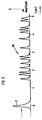
- FIG. 3 shows the pulse sequence 10 (envelope curve) contained in the impulse response of the identification mark 1, which is the response of the coding of the reflector structure 5 to a received burst 11.
- such identification marks are installed at corresponding distances from one another in front of the stop for the train in the track area or also on the tunnel wall.
- each identification mark of such a braking section has its own coding, i.e. is unmistakable with the other identification marks in this section.
- the e.g. the train entering the station runs over it or runs along this sequence of identification marks.
- a program can be calculated or determined in advance from the operating data of the train, according to which the train is more or less decelerated from one identification mark to another when it enters the station, for example.
- the program is selected so that the incoming train can be braked continuously from full speed with a given, in particular the greatest possible deceleration, without the tire of the railroad wheel slipping on the rail at any moment, ie sliding friction occurs.
- the latter would not only wear the tire surfaces considerably more, but due to the undefined nature of the sliding friction, the train would come to a standstill at a very different location than the one specified.
- each individual identification mark can be clearly recognized from the moving train and the current position of the moving train is thus known.
- the speed of the train over ground can also be precisely determined with high accuracy, namely free of any inaccuracies due to slippage, which are inevitable when measuring the driving speed from the rotational speed of the rolling wheel.
- the speed determined exactly with the aid of the identification marks can be used to instantly determine whether the rolling wheel is currently slipping. It only needs the one with the rolling one Wheel determined speed can be compared with the exactly measured value and the difference results as slip.
- the present invention can not only be used in railway operations, but can also be used in other modes of transport in comparable cases. In this respect, the description given below for implementing the invention can then be readily applied to such comparable cases.
- the evaluation method used in accordance with the invention provides for burst pulses 11 to be emitted by a pulse transmitter of a correspondingly high carrier frequency.
- This burst pulse is received by the surface wave structure 3, 5 of the identification mark 1 via the antenna 4 of the identification mark 1 and converted into a characteristic pulse response signal 10 by the latter.
- the characteristic of the impulse response signal depends on the chosen structure of the reflector 5 of the identification mark.
- the impulse response signal sent back from the identification tag to the evaluation device contains further information besides the coding of the reflector. Since the pulse transmitter and impulse response evaluation device attached to the moving train approaches the identification mark at the speed of the train, a Doppler frequency shift occurs in the carrier frequency of the pulse response signal (from which the relative speed between the train and the identification mark can be determined).
- the absolute speed of the train can be easily calculated from the measured relative speed, and without any slip error.
- Exactly when the train passes the respective identification mark as a waypoint can be determined from the course of the measured Doppler frequency shift.
- the zero crossing of the Doppler frequency shift is the location of the waypoint.
- the Doppler shift can be determined and evaluated as a frequency shift or (with correspondingly small values) as a phase shift with respect to a reference phase.
- the invention thus relates to the measures to calculate the course of the relative speed between the identification / way mark and the transmitting / receiving antenna of the transmitting / evaluating device from the Doppler frequency / phase shift of the carrier frequency of the pulse response signal or a part thereof, and thus both to determine true speed as well as the exact position of the train (or other vehicle).
- the coincidence of the position of the train with the position identified by the identification mark is determined with the aid of the zero crossing of the Doppler frequency / phase shift of the carrier frequency of the response signal (or a part thereof).
- the distance between the transmission / reception antenna for the impulse response signal, which is mechanically coupled to the train, and the identification mark when passing over it, if this value is not known in any case, can also be calculated from the Doppler frequency / phase shift. If this distance value is known, the reliability and accuracy of the system according to the invention can be checked at any time by measuring the same as described above from the agreement of the measured value and the known value.
- the exact position of the position of the identification mark as a way mark relative to the train is calculated from the ratio between the speed of the train and its relative speed.
- the direction of the respective connecting line between the identification mark and the transmitting / receiving antenna is calculated from these two speeds at each location on the movement path of the evaluation device.
- the location of the waypoint results from the intersection of this connecting line from different positions of the train, that is, positions of the transmitting / receiving antenna.
- this location also results from the intersection of at least one of these connecting lines with the plumb line described above or with the straight line running parallel to the carriageway, which has the already mentioned plumb line distance between the antenna and the mark when the vehicle passes over it.
- the distance between the identification mark can be calculated as the intersection of the above connecting lines.
- Figure 1 the sectional view of Figure 1 is attached.
- This figure shows the designation 1, which has just been queried, as a way mark in the track area.
- the rail is 29 and a wagon wheel is designated 30.
- Further identification marks as way marks are designated 1 ', 1' '. There can be no confusion, since each of the identification marks emits its own coded, that is, unmistakable impulse response signal when queried.
- the transmission / reception antenna of the evaluation device 8 is designated by 9. Corresponding to the travel path of the car 31 with the wheels 3, this antenna 9 moves on the movement path 20 parallel to the rail 29.
- the vertical distance that is to say the distance between the antenna 9 and the identification mark 1 when it is passed over it, is designated by a. If an interrogation pulse is sent at the moment of the position of the antenna 9 relative to the identification mark 1, a relative speed V rel corresponding to the connecting beam r 1 occurs as the Doppler displacement speed. This speed value is measured as a frequency or phase shift between at least two pulse response signals that are interrogated and received briefly in succession.
- the angle ⁇ is the directional angle of the connecting line r1.
- the coding of the identification mark used as a way mark contains the respectively assigned position number in the sequence of a plurality of way marks arranged at a distance from one another.
- a sequence of waymarks is preferably provided in the braking area in front of a station.
- Such markers can also be provided elsewhere on the route, for example to measure the speed of the train without slippage.
- the identification marks with surface wave structures used as waymarks are passive components that do not require any power supply. Only their range of action is relatively limited, which is an advantage in the present case, namely that interference from the environment is practically excluded.
Landscapes
- Engineering & Computer Science (AREA)
- Mechanical Engineering (AREA)
- Radar, Positioning & Navigation (AREA)
- Remote Sensing (AREA)
- Computer Networks & Wireless Communication (AREA)
- Physics & Mathematics (AREA)
- General Physics & Mathematics (AREA)
- Train Traffic Observation, Control, And Security (AREA)
- Electric Propulsion And Braking For Vehicles (AREA)
Applications Claiming Priority (2)
| Application Number | Priority Date | Filing Date | Title |
|---|---|---|---|
| DE4310610 | 1993-03-31 | ||
| DE4310610A DE4310610A1 (de) | 1993-03-31 | 1993-03-31 | System zur Zielbremsung von Fahrzeugen |
Publications (2)
| Publication Number | Publication Date |
|---|---|
| EP0618459A2 true EP0618459A2 (fr) | 1994-10-05 |
| EP0618459A3 EP0618459A3 (fr) | 1995-08-16 |
Family
ID=6484415
Family Applications (1)
| Application Number | Title | Priority Date | Filing Date |
|---|---|---|---|
| EP94103070A Withdrawn EP0618459A3 (fr) | 1993-03-31 | 1994-03-01 | Système pour arrêrer des véhicules sur une position exacte. |
Country Status (3)
| Country | Link |
|---|---|
| US (1) | US5436631A (fr) |
| EP (1) | EP0618459A3 (fr) |
| DE (1) | DE4310610A1 (fr) |
Cited By (1)
| Publication number | Priority date | Publication date | Assignee | Title |
|---|---|---|---|---|
| WO2015043974A1 (fr) * | 2013-09-30 | 2015-04-02 | Siemens Aktiengesellschaft | Détermination de position d'un véhicule ferroviaire |
Families Citing this family (17)
| Publication number | Priority date | Publication date | Assignee | Title |
|---|---|---|---|---|
| EP0667537A3 (fr) * | 1993-10-04 | 1996-07-17 | Texas Instruments Deutschland | Positionnement avec transpondeurs "RF-ID". |
| DE4336896C2 (de) * | 1993-10-28 | 1995-08-31 | Siemens Ag | Verfahren zur Energieversorgung von mit akustischen Oberflächenwellen arbeitenden und mit aktiver Elektronik beschalteten Identifizierungsmarken |
| DE4405647C2 (de) * | 1994-02-22 | 1999-04-15 | Siemens Ag | Mit akustischen Oberflächenwellen arbeitende Identifizierungsmarke |
| DE19534229A1 (de) | 1995-09-15 | 1997-03-20 | Licentia Gmbh | Transponderanordnung |
| US6760712B1 (en) * | 1997-12-29 | 2004-07-06 | General Electric Company | Automatic train handling controller |
| US6511023B2 (en) * | 1999-01-22 | 2003-01-28 | Sydney Allen Harland | Automated railway monitoring system |
| DE19909479A1 (de) * | 1999-02-09 | 2000-08-10 | Krause Johann A | Verfahren zur Positionsermittlung und/oder Steuerung ortsveränderlicher Komponenten von zum Beispiel Bearbeitungseinrichtungen und Vorrichtung zur Durchführung des Verfahrens |
| DE19911369C2 (de) | 1999-03-15 | 2003-04-03 | Nanotron Ges Fuer Mikrotechnik | Oberflächen-Wellen-Wandler-Einrichtung sowie Identifikationssystem hiermit |
| DE19962472C2 (de) * | 1999-12-22 | 2002-08-01 | Daimler Chrysler Ag | Vorrichtung zur Bestimmung einer Abstandsänderung zweier Seiten eines Körpers, insbesondere eines Karosserieteils eines Fahrzeugs |
| WO2002029435A1 (fr) * | 2000-10-04 | 2002-04-11 | Siemens Aktiengesellschaft | Procede et dispositif de mesure radio du mouvement d'au moins un objet |
| DE10245149A1 (de) * | 2002-09-27 | 2004-04-08 | Maurer Söhne Gmbh & Co. Kg | Bremse und Verfahren zur Regelung der Bremskraft einer Bremse |
| AU2003902168A0 (en) * | 2003-05-07 | 2003-05-22 | Central Queensland University | A control system for operating long vehicles |
| FR2905105B1 (fr) * | 2006-08-25 | 2008-11-21 | Alstom Transport Sa | Dispositif de commande regulee de vehicule a precision recentree. |
| CN102328651B (zh) * | 2011-07-26 | 2013-08-14 | 郑州三瑞共和科技有限公司 | 一种列车中首先发生紧急制动作用的车辆快速定位方法 |
| DE102011118147A1 (de) * | 2011-11-10 | 2013-05-16 | Gm Global Technology Operations, Llc | Verfahren zum Ermitteln einer Geschwindigkeit eines Fahrzeugs und Fahrzeug |
| US10279823B2 (en) * | 2016-08-08 | 2019-05-07 | General Electric Company | System for controlling or monitoring a vehicle system along a route |
| DE102021206165A1 (de) * | 2021-06-16 | 2022-12-22 | Pepperl+Fuchs Se | Messeinrichtung und messverfahren |
Citations (2)
| Publication number | Priority date | Publication date | Assignee | Title |
|---|---|---|---|---|
| US4703327A (en) * | 1985-10-31 | 1987-10-27 | X-Cyte, Inc. | Interrogator/receiver system for use with a remote transponder |
| US4739329A (en) * | 1986-04-16 | 1988-04-19 | Motorola, Inc. | Scaler scoring system |
Family Cites Families (17)
| Publication number | Priority date | Publication date | Assignee | Title |
|---|---|---|---|---|
| GB1479616A (en) * | 1974-10-15 | 1977-07-13 | Standard Telephones Cables Ltd | Train position indication |
| US4096477A (en) * | 1975-10-06 | 1978-06-20 | Northwestern University | Identification system using coded passive transponders |
| DE2632902A1 (de) * | 1976-07-21 | 1978-01-26 | Siemens Ag | Flaechenstrahlerantenne fuer ein abfragegeraet auf einem schienenfahrzeug |
| DE2942933A1 (de) * | 1979-10-24 | 1981-05-21 | Licentia Patent-Verwaltungs-Gmbh, 6000 Frankfurt | Vorrichtung zur weg-/geschwindigkeitsmessung schienengebundener fahrzeuge |
| DE3043461A1 (de) * | 1980-11-18 | 1982-07-08 | Licentia Patent-Verwaltungs-Gmbh, 6000 Frankfurt | Verfahren zur entfernungsmessung zwischen einem spurgebundenen fahrzeug und einer ortsfesten station |
| GB2093593A (en) * | 1981-02-20 | 1982-09-02 | Coal Industry Patents Ltd | Method of and equipment for sensing speed of travel |
| DE3345707A1 (de) * | 1983-12-17 | 1985-06-27 | Brown, Boveri & Cie Ag, 6800 Mannheim | Sicherheitseinrichtung |
| AU565454B2 (en) * | 1984-10-09 | 1987-09-17 | X-Cyte Inc. | Saw transponder |
| FR2592959B1 (fr) * | 1986-01-15 | 1988-09-09 | Jeumont Schneider | Cinemometre radar a effet doppler |
| JPS63136199A (ja) * | 1986-11-27 | 1988-06-08 | 住友電気工業株式会社 | 路側ビ−コン方式 |
| US4899158A (en) * | 1987-09-26 | 1990-02-06 | Matsushita Electric Works, Ltd. | Moving object discriminating system |
| DE3821215C2 (de) * | 1988-06-23 | 1993-11-18 | Deutsche Aerospace | Geschwindigkeits-Wegstrecken-Sensor für Kraftfahrzeuganordnungen |
| DE3828447C2 (de) * | 1988-08-22 | 1998-03-12 | Eisenmann Kg Maschbau | Optische Leitvorrichtung für fahrerlose Transportsysteme |
| DE4012668A1 (de) * | 1990-04-20 | 1991-10-31 | W & M Engineering & Automation | Rocar-steuerung |
| FR2672026B1 (fr) * | 1991-01-24 | 1993-05-21 | Aigle Azur Concept | Dispositif de controle automatique de vitesse d'arret, et d'aide a la conduite du vehicule, notamment ferroviaire. |
| DE4117157A1 (de) * | 1991-05-25 | 1993-03-25 | Telefunken Systemtechnik | Elektromagnetische einweisevorrichtung |
| IL98498A (en) * | 1991-06-14 | 1994-01-25 | Vardi Shlomo | Electro-optical monitoring system for vehicles |
-
1993
- 1993-03-31 DE DE4310610A patent/DE4310610A1/de not_active Withdrawn
-
1994
- 1994-03-01 EP EP94103070A patent/EP0618459A3/fr not_active Withdrawn
- 1994-03-08 US US08/207,162 patent/US5436631A/en not_active Expired - Fee Related
Patent Citations (2)
| Publication number | Priority date | Publication date | Assignee | Title |
|---|---|---|---|---|
| US4703327A (en) * | 1985-10-31 | 1987-10-27 | X-Cyte, Inc. | Interrogator/receiver system for use with a remote transponder |
| US4739329A (en) * | 1986-04-16 | 1988-04-19 | Motorola, Inc. | Scaler scoring system |
Non-Patent Citations (1)
| Title |
|---|
| REVUE GENERALE DES CHEMINS DE FER, Nr. 12, Dezember 1990 PARIS FR, Seiten 5-20, XP 000208705 A. BLANC 'le controle de vitesse' * |
Cited By (1)
| Publication number | Priority date | Publication date | Assignee | Title |
|---|---|---|---|---|
| WO2015043974A1 (fr) * | 2013-09-30 | 2015-04-02 | Siemens Aktiengesellschaft | Détermination de position d'un véhicule ferroviaire |
Also Published As
| Publication number | Publication date |
|---|---|
| DE4310610A1 (de) | 1994-10-06 |
| EP0618459A3 (fr) | 1995-08-16 |
| US5436631A (en) | 1995-07-25 |
Similar Documents
| Publication | Publication Date | Title |
|---|---|---|
| EP0618459A2 (fr) | Système pour arrêrer des véhicules sur une position exacte | |
| EP1701287B1 (fr) | Système d'identification et procédé de détection d'informations de mouvement | |
| EP2537044B1 (fr) | Détecteur radar intégré dans la chaussée | |
| DD292880A5 (de) | Steuerungssystem fuer die abfolge mehrerer eisenbahnzuege auf einem netz | |
| DE2430378B2 (de) | Automatische gleislose Flurförderanlage | |
| DE2124089C3 (de) | Einrichtung bei Schienenbahnen zur Informationsübertragung von der Strecke auf die Fahrzeuge | |
| EP0715579B1 (fr) | Systeme de liberation de l'ouverture des portes de vehicules sur rails | |
| EP4077098A1 (fr) | Procédé et système de surveillance pour déterminer une position d'un véhicule ferroviaire | |
| WO1996014626A1 (fr) | Procede pour determiner la position d'un vehicule sur une route | |
| DE4411125A1 (de) | Informationssystem | |
| EP3515787A1 (fr) | Procédé de détermination de la position d'un véhicule ferroviaire et véhicule ferroviaire avec système de détermination de position | |
| DE3200811A1 (de) | Einrichtung zur bestimmung des standortes eines spurgefuehrten fahrzeugs | |
| DE102009015540A1 (de) | Verfahren und Vorrichtung zur Geschwindigkeitsüberwachung | |
| WO2008006803A1 (fr) | Système, en particulier système de trafic ferroviaire à petite distance, et procédé pour la détection du trajet côté véhicule pour un tel système | |
| EP0403954B1 (fr) | Dispositif de signalisation de voie libre pour les chemins de fer | |
| EP1447679B1 (fr) | Dispositif et procédé pour mesurer la distance entre deux points d'un objet, en particulier pour mesurer le diamètre d'une roue d'un véhicule ferroviaire | |
| EP0618460A2 (fr) | Système pour la détermination de la position et/ou de la vitesse d'un objet en utilisant un marqueur d'identification à ondes de surface, à utiliser notamment dans les systèmes de chargement et déplacement | |
| DE3207092A1 (de) | Positionierungsvorrichtung fuer ein schienengebundenes fahrzeug, vorzugsweise einen kran | |
| EP0374294A1 (fr) | Dispositif de transmission d'information à un véhicule à voie de guidage | |
| EP3795449A1 (fr) | Procédé amélioré de localisation, en particulier d'un véhicule ferroviaire et dispositif de localisation approprié | |
| DE2739231C3 (de) | Einrichtung zur Eigenortung spurgebundener Fahrzeuge | |
| DE3300429A1 (de) | Einrichtung zur zuglaengenmessung | |
| DE2942933A1 (de) | Vorrichtung zur weg-/geschwindigkeitsmessung schienengebundener fahrzeuge | |
| DE1930641C3 (de) | Einrichtung zur Fahrortermittlung für Schienenfahrzeuge | |
| DE3235733A1 (de) | Einrichtung zur gleisfreimeldung |
Legal Events
| Date | Code | Title | Description |
|---|---|---|---|
| PUAI | Public reference made under article 153(3) epc to a published international application that has entered the european phase |
Free format text: ORIGINAL CODE: 0009012 |
|
| AK | Designated contracting states |
Kind code of ref document: A2 Designated state(s): AT CH DE DK ES FR GB IT LI NL SE |
|
| PUAL | Search report despatched |
Free format text: ORIGINAL CODE: 0009013 |
|
| AK | Designated contracting states |
Kind code of ref document: A3 Designated state(s): AT CH DE DK ES FR GB IT LI NL SE |
|
| 17P | Request for examination filed |
Effective date: 19960205 |
|
| STAA | Information on the status of an ep patent application or granted ep patent |
Free format text: STATUS: THE APPLICATION IS DEEMED TO BE WITHDRAWN |
|
| 18D | Application deemed to be withdrawn |
Effective date: 19971001 |