EP0618147B1 - Selbstreinigender Luftpumpenspender - Google Patents
Selbstreinigender Luftpumpenspender Download PDFInfo
- Publication number
- EP0618147B1 EP0618147B1 EP93306716A EP93306716A EP0618147B1 EP 0618147 B1 EP0618147 B1 EP 0618147B1 EP 93306716 A EP93306716 A EP 93306716A EP 93306716 A EP93306716 A EP 93306716A EP 0618147 B1 EP0618147 B1 EP 0618147B1
- Authority
- EP
- European Patent Office
- Prior art keywords
- liquid
- air
- exit port
- chamber
- piston
- Prior art date
- Legal status (The legal status is an assumption and is not a legal conclusion. Google has not performed a legal analysis and makes no representation as to the accuracy of the status listed.)
- Expired - Lifetime
Links
- 238000010926 purge Methods 0.000 title abstract description 10
- 239000007788 liquid Substances 0.000 claims abstract description 218
- 230000009471 action Effects 0.000 claims abstract description 11
- 239000007921 spray Substances 0.000 claims abstract description 11
- 230000000694 effects Effects 0.000 claims description 6
- 238000004891 communication Methods 0.000 claims description 3
- 230000002829 reductive effect Effects 0.000 claims description 2
- 230000004044 response Effects 0.000 claims description 2
- 238000011144 upstream manufacturing Methods 0.000 claims description 2
- 239000000203 mixture Substances 0.000 abstract description 10
- 238000009472 formulation Methods 0.000 abstract description 7
- XLYOFNOQVPJJNP-UHFFFAOYSA-N water Substances O XLYOFNOQVPJJNP-UHFFFAOYSA-N 0.000 abstract description 5
- 239000000443 aerosol Substances 0.000 abstract 1
- 239000003570 air Substances 0.000 description 181
- 239000012530 fluid Substances 0.000 description 14
- 238000007789 sealing Methods 0.000 description 8
- 230000008901 benefit Effects 0.000 description 5
- 239000012855 volatile organic compound Substances 0.000 description 5
- 230000002093 peripheral effect Effects 0.000 description 4
- 230000002441 reversible effect Effects 0.000 description 4
- LFQSCWFLJHTTHZ-UHFFFAOYSA-N Ethanol Chemical compound CCO LFQSCWFLJHTTHZ-UHFFFAOYSA-N 0.000 description 2
- 239000012080 ambient air Substances 0.000 description 2
- 238000010586 diagram Methods 0.000 description 2
- 230000007613 environmental effect Effects 0.000 description 2
- 230000001939 inductive effect Effects 0.000 description 2
- 230000000670 limiting effect Effects 0.000 description 2
- 239000003380 propellant Substances 0.000 description 2
- 230000009467 reduction Effects 0.000 description 2
- 239000007787 solid Substances 0.000 description 2
- 150000001875 compounds Chemical class 0.000 description 1
- 238000010276 construction Methods 0.000 description 1
- 230000000994 depressogenic effect Effects 0.000 description 1
- 238000001704 evaporation Methods 0.000 description 1
- 230000008020 evaporation Effects 0.000 description 1
- 239000006260 foam Substances 0.000 description 1
- 239000008266 hair spray Substances 0.000 description 1
- 230000003993 interaction Effects 0.000 description 1
- 230000007246 mechanism Effects 0.000 description 1
- 238000000034 method Methods 0.000 description 1
- 230000004048 modification Effects 0.000 description 1
- 238000012986 modification Methods 0.000 description 1
- 230000036961 partial effect Effects 0.000 description 1
- 230000035515 penetration Effects 0.000 description 1
- 230000037452 priming Effects 0.000 description 1
- 230000008569 process Effects 0.000 description 1
- 230000000717 retained effect Effects 0.000 description 1
- 230000000630 rising effect Effects 0.000 description 1
- 238000000926 separation method Methods 0.000 description 1
- 239000002904 solvent Substances 0.000 description 1
Images


Classifications
-
- B—PERFORMING OPERATIONS; TRANSPORTING
- B05—SPRAYING OR ATOMISING IN GENERAL; APPLYING FLUENT MATERIALS TO SURFACES, IN GENERAL
- B05B—SPRAYING APPARATUS; ATOMISING APPARATUS; NOZZLES
- B05B7/00—Spraying apparatus for discharge of liquids or other fluent materials from two or more sources, e.g. of liquid and air, of powder and gas
- B05B7/0018—Spraying apparatus for discharge of liquids or other fluent materials from two or more sources, e.g. of liquid and air, of powder and gas with devices for making foam
- B05B7/0025—Spraying apparatus for discharge of liquids or other fluent materials from two or more sources, e.g. of liquid and air, of powder and gas with devices for making foam with a compressed gas supply
- B05B7/0031—Spraying apparatus for discharge of liquids or other fluent materials from two or more sources, e.g. of liquid and air, of powder and gas with devices for making foam with a compressed gas supply with disturbing means promoting mixing, e.g. balls, crowns
-
- B—PERFORMING OPERATIONS; TRANSPORTING
- B05—SPRAYING OR ATOMISING IN GENERAL; APPLYING FLUENT MATERIALS TO SURFACES, IN GENERAL
- B05B—SPRAYING APPARATUS; ATOMISING APPARATUS; NOZZLES
- B05B11/00—Single-unit hand-held apparatus in which flow of contents is produced by the muscular force of the operator at the moment of use
- B05B11/01—Single-unit hand-held apparatus in which flow of contents is produced by the muscular force of the operator at the moment of use characterised by the means producing the flow
- B05B11/10—Pump arrangements for transferring the contents from the container to a pump chamber by a sucking effect and forcing the contents out through the dispensing nozzle
- B05B11/1001—Piston pumps
- B05B11/1016—Piston pumps the outlet valve having a valve seat located downstream a movable valve element controlled by a pressure actuated controlling element
- B05B11/1019—Piston pumps the outlet valve having a valve seat located downstream a movable valve element controlled by a pressure actuated controlling element the inlet valve moving concurrently with the controlling element during whole pressure and aspiration strokes, e.g. a cage for an inlet valve ball being part of the controlling element
-
- B—PERFORMING OPERATIONS; TRANSPORTING
- B05—SPRAYING OR ATOMISING IN GENERAL; APPLYING FLUENT MATERIALS TO SURFACES, IN GENERAL
- B05B—SPRAYING APPARATUS; ATOMISING APPARATUS; NOZZLES
- B05B11/00—Single-unit hand-held apparatus in which flow of contents is produced by the muscular force of the operator at the moment of use
- B05B11/01—Single-unit hand-held apparatus in which flow of contents is produced by the muscular force of the operator at the moment of use characterised by the means producing the flow
- B05B11/10—Pump arrangements for transferring the contents from the container to a pump chamber by a sucking effect and forcing the contents out through the dispensing nozzle
- B05B11/1087—Combination of liquid and air pumps
-
- B—PERFORMING OPERATIONS; TRANSPORTING
- B05—SPRAYING OR ATOMISING IN GENERAL; APPLYING FLUENT MATERIALS TO SURFACES, IN GENERAL
- B05B—SPRAYING APPARATUS; ATOMISING APPARATUS; NOZZLES
- B05B11/00—Single-unit hand-held apparatus in which flow of contents is produced by the muscular force of the operator at the moment of use
- B05B11/01—Single-unit hand-held apparatus in which flow of contents is produced by the muscular force of the operator at the moment of use characterised by the means producing the flow
- B05B11/10—Pump arrangements for transferring the contents from the container to a pump chamber by a sucking effect and forcing the contents out through the dispensing nozzle
- B05B11/1097—Pump arrangements for transferring the contents from the container to a pump chamber by a sucking effect and forcing the contents out through the dispensing nozzle with means for sucking back the liquid or other fluent material in the nozzle after a dispensing stroke
-
- B—PERFORMING OPERATIONS; TRANSPORTING
- B05—SPRAYING OR ATOMISING IN GENERAL; APPLYING FLUENT MATERIALS TO SURFACES, IN GENERAL
- B05B—SPRAYING APPARATUS; ATOMISING APPARATUS; NOZZLES
- B05B7/00—Spraying apparatus for discharge of liquids or other fluent materials from two or more sources, e.g. of liquid and air, of powder and gas
- B05B7/0018—Spraying apparatus for discharge of liquids or other fluent materials from two or more sources, e.g. of liquid and air, of powder and gas with devices for making foam
- B05B7/0025—Spraying apparatus for discharge of liquids or other fluent materials from two or more sources, e.g. of liquid and air, of powder and gas with devices for making foam with a compressed gas supply
- B05B7/0031—Spraying apparatus for discharge of liquids or other fluent materials from two or more sources, e.g. of liquid and air, of powder and gas with devices for making foam with a compressed gas supply with disturbing means promoting mixing, e.g. balls, crowns
- B05B7/0037—Spraying apparatus for discharge of liquids or other fluent materials from two or more sources, e.g. of liquid and air, of powder and gas with devices for making foam with a compressed gas supply with disturbing means promoting mixing, e.g. balls, crowns including sieves, porous members or the like
-
- G—PHYSICS
- G01—MEASURING; TESTING
- G01F—MEASURING VOLUME, VOLUME FLOW, MASS FLOW OR LIQUID LEVEL; METERING BY VOLUME
- G01F11/00—Apparatus requiring external operation adapted at each repeated and identical operation to measure and separate a predetermined volume of fluid or fluent solid material from a supply or container, without regard to weight, and to deliver it
- G01F11/02—Apparatus requiring external operation adapted at each repeated and identical operation to measure and separate a predetermined volume of fluid or fluent solid material from a supply or container, without regard to weight, and to deliver it with measuring chambers which expand or contract during measurement
- G01F11/021—Apparatus requiring external operation adapted at each repeated and identical operation to measure and separate a predetermined volume of fluid or fluent solid material from a supply or container, without regard to weight, and to deliver it with measuring chambers which expand or contract during measurement of the piston type
- G01F11/025—Apparatus requiring external operation adapted at each repeated and identical operation to measure and separate a predetermined volume of fluid or fluent solid material from a supply or container, without regard to weight, and to deliver it with measuring chambers which expand or contract during measurement of the piston type with manually operated pistons
- G01F11/028—Apparatus requiring external operation adapted at each repeated and identical operation to measure and separate a predetermined volume of fluid or fluent solid material from a supply or container, without regard to weight, and to deliver it with measuring chambers which expand or contract during measurement of the piston type with manually operated pistons the dosing device being provided with a dip tube and fitted to a container, e.g. to a bottleneck
-
- B—PERFORMING OPERATIONS; TRANSPORTING
- B05—SPRAYING OR ATOMISING IN GENERAL; APPLYING FLUENT MATERIALS TO SURFACES, IN GENERAL
- B05B—SPRAYING APPARATUS; ATOMISING APPARATUS; NOZZLES
- B05B1/00—Nozzles, spray heads or other outlets, with or without auxiliary devices such as valves, heating means
- B05B1/34—Nozzles, spray heads or other outlets, with or without auxiliary devices such as valves, heating means designed to influence the nature of flow of the liquid or other fluent material, e.g. to produce swirl
- B05B1/3405—Nozzles, spray heads or other outlets, with or without auxiliary devices such as valves, heating means designed to influence the nature of flow of the liquid or other fluent material, e.g. to produce swirl to produce swirl
- B05B1/341—Nozzles, spray heads or other outlets, with or without auxiliary devices such as valves, heating means designed to influence the nature of flow of the liquid or other fluent material, e.g. to produce swirl to produce swirl before discharging the liquid or other fluent material, e.g. in a swirl chamber upstream the spray outlet
- B05B1/3421—Nozzles, spray heads or other outlets, with or without auxiliary devices such as valves, heating means designed to influence the nature of flow of the liquid or other fluent material, e.g. to produce swirl to produce swirl before discharging the liquid or other fluent material, e.g. in a swirl chamber upstream the spray outlet with channels emerging substantially tangentially in the swirl chamber
- B05B1/3431—Nozzles, spray heads or other outlets, with or without auxiliary devices such as valves, heating means designed to influence the nature of flow of the liquid or other fluent material, e.g. to produce swirl to produce swirl before discharging the liquid or other fluent material, e.g. in a swirl chamber upstream the spray outlet with channels emerging substantially tangentially in the swirl chamber the channels being formed at the interface of cooperating elements, e.g. by means of grooves
- B05B1/3436—Nozzles, spray heads or other outlets, with or without auxiliary devices such as valves, heating means designed to influence the nature of flow of the liquid or other fluent material, e.g. to produce swirl to produce swirl before discharging the liquid or other fluent material, e.g. in a swirl chamber upstream the spray outlet with channels emerging substantially tangentially in the swirl chamber the channels being formed at the interface of cooperating elements, e.g. by means of grooves the interface being a plane perpendicular to the outlet axis
Definitions
- This invention relates to dispensing apparatus for dispensing liquids by pump action as an atomised spray and in particular but not exclusively to apparatus for dispensing water based products.
- pressurised dispensers containing volatile propellants deliver optimum performance for hair sprays and other personal care formulations.
- use of such propellants will be minimized in the near future.
- Pump dispensers are an acceptable alternative, providing that alcohol is used as a solvent of these formulations to minimize the tendency to clog. Nevertheless, alcohol is a volatile organic compound (VOC) and such compounds also create environmental damage. Future VOC standards will limit the use of VOCs.
- VOC volatile organic compound
- VOCs The obvious substitute for VOCs is water. Nevertheless, water based formulations cause known types of pump dispensers to clog, particularly when the formulations contain high percentages of solids.
- a further problem is that the discharge orifice can become obstructed, causing the dispenser to fail.
- a disadvantage of the proposed dispenser is that the air is pumped from a cylinder formed by cap-like handle of the actuating means containing complex multi-component valve structures.
- apparatus for dispensing liquid by pump action as an atomized spray comprising a body defining a first cylinder within which a first piston is reciprocatably located to define a first chamber of variable volume and which in use contains a quantity of liquid to be dispensed; a second cylinder with a second piston to define a second chamber of variable volume which in use contains a quantity of air; actuating means operable during an actuating stroke to effect relative movement between the pistons and respective cylinders in directions such that the volumes of the respective chambers are reduced and during a return stroke to effect return movement to respective rest positions in which the respective chambers are expanded; liquid valve means operable to admit liquid to the first chamber during at least part of the return stroke and release pressurised liquid therefrom during at least part of the actuating stroke, the liquid valve means comprising a liquid exit port for the release of liquid from the first chamber; channel means defining a discharge orifice and a dispensing channel communicating between the liquid exit port and the discharge orifice,
- the second chamber and second piston thereby constitute an air pump which is essentially contained within the body of the apparatus thereby enabling the apparatus to be more compact and avoiding the need for the air pump to be located within an enlarged actuator external to the body.
- the second cylinder is located intermediate the first cylinder and the actuating means and the second piston comprises a hollow upper extension through which a hollow upper extension of the first piston extends whereby the first and second pistons are nested together so as to be axially displaced relative to the body substantially in unison by movement of the actuating means.
- the liquid valve means is operable to close the liquid exit port before completion of the actuating stroke such that during a terminal part of the actuating stroke the release of liquid from the first chamber is arrested.
- the flow of air then continueas after the flow of liquid has ceased in order to purge liquid from the dispensing channel and discharge orifice to thereafter prevent clogging and obstruction.
- the liquid exit port is opened in response to an increase in pressure of liquid within the first chamber, the apparatus further comprising pressure relief means operable to reduce the liquid pressure within the first chamber during the terminal part of the actuating stroke to thereby effect closure of the liquid valve means.
- the liquid valve means comprises an elongate stem having an upper portion extending into the hollow upper extension of the first piston which is movable into and out of engagement with the first piston to close and open the liquid exit port respectively and a lower portion which extends through the first cylinder and includes a lower end which is peripherally engageable with an internal surface of the body thereby normally closing the first chamber, the surface being provided with a recess to allow liquid to by-pass the lower end during the terminal part of the actuating stroke to thereby constitute the pressure relief means.
- An advantage of this arrangement is that the position of the pistons during the actuating stroke at which the liquid flow is replaced by air flow can be easily determined by the position of the recess relative to the axial extent of the first chamber.
- the apparatus may comprise an air valve means operable to release air compressed within the second chamber and comprising an air exit port communicating with the dispensing channel, the air valve means being operable such that the air exit port is open during at least part of the actuating stroke and closed during the return stroke.
- the air valve means and the liquid valve means are co-operable such that on commencement of the terminal part of the actuating stroke the liquid exit port closes and the air exit port opens.
- the air exit port is defined between an annular upper end portion of the hollow upper extension of the first piston and an internal wall of the hollow upper extension of the second piston which are relatively movable to open and close the air exit port and thereby constitute the air valve means.
- liquid exit port is defined by the annular upper end portion of the first piston whereby the air exit port is located immediately adjacent the liquid exit port.
- An advantage of this arrangement is that the air exit port being adjacent to the liquid exit port enables all liquid downstream of the liquid exit port to be purged by the air flow during the terminal portion of the dispensing stroke.
- the air valve means may further comprise an air entry port communicating with the second chamber and which is open at the end of the return stroke to admit air into the second chamber.
- the second chamber is thereby recharged with air in readiness for the next actuation.
- the air conduit means comprises an air conduit defined by the hollow upper extension of the second piston which is continuously in communication with the dispensing channel via a continuously open air exit port whereby air enters the second chamber via the dispensing channel during the return stroke.
- the air exit port is defined between an annular upper end of the hollow upper extension of the first piston and an internal wall of the hollow upper extension of the second piston, the liquid exit port being defined by the annular upper end portion of the hollow upper extension of the first piston whereby the air exit port is located immediately adjacent the liquid exit port.
- An advantage of this arrangement is that the air exit port being located adjacent to the liquid exit port ensures that the discharge channel is fully purged of residual liquid.
- the channel means defines a mixing chamber located downstream of both the air exit port and the liquid exit port, the mixing chamber being upstream of the discharge orifice whereby air and liquid are mixed prior to discharge.
- the air exit port remains continuously open, air is mixed with the liquid during the dispensing stroke thereby assisting in the pressurising and atomising of the liquid.
- the presence of the mixing chamber assists in the entrainment of air bubbles in the liquid prior to discharge.
- the channel means comprises an air channel and a liquid channel formed separately from the air channel, the air channel and the liquid channel extending from their respective air and liquid exit ports to a location immediately adjacent the discharge orifice at which they are joined so as to provide mixing of air and liquid immediately prior to discharge.
- the second cylinder extends vertically and has open upper and lower ends, the inner surface of the second cylinder adjacent the upper end having an air conduit.
- the air conduit can be a horizontally extending groove disposed in the inner surface of the second cylinder.
- the first cylinder has a diameter smaller than that of the second cylinder and has open upper and lower ends, the lower end of the second cylinder merging with the upper end of the first cylinder.
- a third vertical cylinder has a diameter smaller than that of the first cylinder and has an open upper end and a lower end which is closed except for a central opening, the lower end of the first cylinder merging with the upper end of the third cylinder.
- An elongated stem has an upper portion which extends upwardly through the upper end of the second cylinder and has a lower portion which extends downwardly through the first and second cylinders with a lower end which is peripherally engageable with the inner surface of the third cylinder.
- a first piston has an upper hollow extension with an open upper end, the upper portion of the stem extending within and being spaced from the upper extension of the first piston thus defining a liquid conduit therebetween.
- the first piston has a lower extension extending downwardly through the second cylinder into the first cylinder with a lower end which is peripherally engageable with the inner surface of the first cylinder.
- the second piston has a hollow upper section, the upper extension of the first piston extending within and being spaced from the upper section of the second piston, thus defining an air conduit therebetween.
- the second piston has a lower section with an outward extension which is peripherally engageable with the inner wall of the second cylinder.
- a collar covering the upper end of the second cylinder has a central opening through which the upper portion of the stem, the upper extension of the first piston and the upper section of the second piston extend, the collar having an integral vertical wall secured to the outer periphery of the upper end of the second cylinder and extending downwardly in such manner that an air entry channel is formed therebetween.
- the air entry channel and the groove define an air entry port which is open when the outer periphery of the lower end of the lower section is aligned with said groove and which is closed when this outer periphery engages the inner wall of the second cylinder, the air entry port when open interconnecting the air conduit with the air channel.
- Each of the first and second pistons are movable between raised and lowered positions, the first piston and the second piston being engageable with and disengageable from each other, the first and second pistons when disengaged defining an open air exit port and when engaged defining a closed air exit port.
- the stem is movable between raised and lowered positions, the stem and first piston being engageable with and disengageable from each other, the stem and first piston when disengaged defining an open liquid exit port and when engaged defining a closed liquid exit port.
- the upper and lower portions of the stem are co-operable in such manner that the upper end of the lower portion and the lower end of the upper portion can be sealed together to define a closed liquid entry port and can be moved away from each other to define a liquid channel therebetween forming an open liquid entry port.
- the lower portion of the stem can be hollow and open at its bottom end. Biasing means extending within the lower portion and the third cylinder can normally bias the liquid entry port into closed position.
- the apparatus is connected to a suitable container filled with a product to be dispensed.
- a dip tube is connected to the central opening of the third cylinder and extends into the formulation.
- the collar, second piston and the second cylinder define the second chamber, referred to below as an air chamber.
- the first and second pistons, the stem and the first cylinder define a first chamber, referred to below as a liquid chamber, which communicates with the liquid conduit.
- the liquid is incompressible and the pressure in the liquid chamber changes immediately.
- this pressure exceeds the bias force on the stem, the lower portion of the stem moves downward with respect to the first piston, the liquid exit port is opened and the pump dispenses liquid at a predetermined pressure.
- the pressure in the air chamber rises inversely with the reduction in the volume of the air chamber caused by the downward movement of the second piston.
- the first piston moves downward with respect to the second piston, the air exit port opens and air is introduced into the liquid stream.
- the liquid entry port is opened and the pressure in the liquid chamber drops, causing the liquid exit port to close.
- the air exit port remains open and the component in the stream continues to be discharged, so that the dispenser sprays air and purges the external channels of remaining liquid.
- the liquid pressure can be relieved at any point during the downstroke by locating a recess on the inner wall of the third cylinder, disposed in any position between the upper and lower ends of the third cylinder which is selected to define the point at which the liquid pressure is to be relieved.
- a recess on the inner wall of the third cylinder disposed in any position between the upper and lower ends of the third cylinder which is selected to define the point at which the liquid pressure is to be relieved.
- ambient air is allowed to enter the second cylinder via the passages between the collar and the second piston and from there into the head space of the package.
- the liquid chamber is refilled with fluid due to the check valving interaction of the upper and lower portions of the stem. The air is allowed to enter into the air chamber at the top of the return stroke.
- the terminal portion of the liquid channel may extend linearly in line with the discharge orifice.
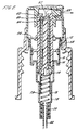
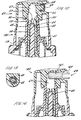
- an air purge pump dispenser 1 comprises a body 71 which is generally tubular and of stepped diameter to define first, second and third cylinders 14, 10 and 18 respectively.
- the second cylinder 10 is uppermost and has open upper and lower ends 2 and 3, and an inner surface 12 which is recessed adjacent the upper end to provide a horizontal groove 12 constituting an air conduit as will be further explained below.
- the first vertical cylinder 14 depends from the second cylinder 10 having a diameter smaller than that of the second cylinder 10 and has open upper and lower ends 4 and 5, the lower end 3 of the second cylinder merging with the upper end of the first cylinder at an inner ledge 16.
- a third vertical cylinder 18 depends from the first cylinder 14 having a diameter smaller than that of the first cylinder 14, and has an open upper end 6 and a lower end 7 which is closed except for a central opening 20.
- the third cylinder 18 has a re-entrant inner wall 21 extending downwardly from the central opening 20, the inner wall having a lower end 8 joined to a lower extension 23 of the third cylinder 18.
- Inner wall 21 and extension 23 are joined at a circular inner groove 25 and the space within extension 23 forms an annular region which supports a spring 36.
- the lower end 5 of the first cylinder 14 merges with the upper end 6 of the third cylinder 18 at an inner ledge 22.
- the third cylinder 18 has an inner surface 9 which is provided with a recess 78 adjacent but above the lower end 7.
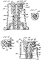
- a two part elongated stem 24,26 has an upper portion 24 which extends upwardly through the upper end 2 of the second cylinder 10 and has a separately formed lower portion 26 which extends downwardly through the first and third cylinders 14 and 18, the lower portion 26 having a lower end 29 which is maintained in peripherally sealing engagement with the inner surface 9 of the third cylinder 18.
- the lower portion 26 of the stem is held in sealing engagement with the upper portion 24 by action of spring 36.
- the lower portion 26 is movable in use out of contact with the upper portion 24, as for example as shown in Figures 1a and 5 to define a liquid entry port 31.
- Sealing engagement is effected between a radially outwardly projecting ring 28 formed integrally with the upper portion 24 and an outwardly and upwardly flaring surface 30 provided on the upper end 33 of the lower portion 26 as shown in Figure 1a so that surface 30 peripherally engages ring 28 in sealing engagement when the liquid entry port 31 is closed and is spaced below ring 28 when the port is open.
- a ring 32 formed integrally with the lower portion 26 projects radially inwardly at the upper end 33 adjacent the surface 30.
- the upper portion 26 has a lower end 37 in which an annular recess 34 is peripherally formed and which receives an uppermost turn 39 of spring 36. This turn 39 is disposed below ring 32 and has a larger diameter.
- the lower end 37 of the upper portion 24 projects through the ring 32 to an extent which is limited by engagement with the uppermost turn 39 in the recess 34 so that the upper and lower portions 24 and 26 of the stem are always retained in sliding engagement whether the liquid entry port is open or closed.
- the recess 34 has spaced vertical conduits 38 for conducting fluid into and out of the liquid entry port 31 when it is open.
- a first piston 41 has a hollow upper extension 40 with an open upper end 43, the upper portion 24 of the stem extending within and being spaced from the upper extension thus defining a liquid conduit 42 therebetween.
- the open upper end 43 of the first piston 41 defines an aperture which is much smaller in cross-section than the size of ring 28 so that excess pressure of liquid in liquid conduit 42 will produce a net downward fore on the upper portion 24 of the stem.
- the first piston 41 has a lower extension 44 extending downwardly through the second cylinder 10 into the first cylinder 14 with a radially enlarged lower end 46 which is maintained in peripherally sealing engagement with the inner surface of the first cylinder. When the first piston 41 is in its fully lowered position as shown in Figure 4, the lower end 46 engages the ledge 22 thereby limiting downward travel of the first piston.
- a second piston 45 has a hollow upper section 48, the upper extension 40 of the first piston 41 extending within and being spaced from the upper section, thus defining an air conduit 50 therebetween.
- the second piston 45 has a lower section 52 with an annular radially outward extension 54 which is peripherally engageable with an inner wall 47 of the second cylinder 10. When the second piston 45 is in its fully lowered position as shown in Figure 4, extension 54 engages ledge 16 thereby limiting downward travel of the second piston.
- a collar 56 covers the upper end of the second cylinder 10 and has a central opening 49 through which the upper portion 24 of the stem, the upper extension 40 of the first piston 41 and the upper section 48 of the second piston 45 extend, the collar having an integral vertical wall 51 secured peripherally to the upper end 2 of the second cylinder 10 and extending downwardly in such manner that an air entry channel 58 is formed therebetween.
- the air entry channel 58 and the groove 12 define an air entry port 53 which is open when the second piston 45 is fully raised in the rest position of Figure 1 in which the outward extension 54 of the second piston 45 is aligned with the groove.
- the air entry port 53 is closed when the outward extension 54 engages the inner wall 47 of the second cylinder 10 when the second piston is moved downwards as shown in Figures 2, 3 and 4.
- the air entry port 53 When the air entry port 53 is open (as in Figure 1) it provides communication between the air entry channel 58 and the air conduit 50.
- the wall 51 is integrally joined to a cup 63 of larger diameter and which is screw threaded for connection to the mouth of a container (not shown)
- first and second pistons 41 and 45 are movable between respective raised and lowered positions.
- the upper ends 60 and 62 of the first piston 41 and the second piston 45 respectively are sealingly engageable with and disengageable from each other; when disengaged, these upper ends define an air exit port 55 communicating with the air conduit 50 which is open as shown in Figure 3.
- the air exit port 55 is closed.
- the stem 24,26 is movable between raised and lowered positions.
- An upper end 64 of the upper portion 24 of the stem and the upper end 60 of the upper extension 40 of the first piston 41 are sealingly engageable with and disengageable from each other; when disengaged as in Figure 2, these upper ends 64 and 60 define an open liquid exit port 57 and when engaged as in Figure 1 the liquid exit port is closed.
- the lower portion 26 of the stem is hollow and open at its bottom end 29.
- the bottom end 29 of the lower portion 26 has a radially outwardly projecting rib 79 which makes sliding contact with the inner wall of the third cylinder 18 so that the lower portion 26 remains spaced from the third cylinder 18 by a small clearance.
- Biasing means in the form of the spring 36 extends within the lower portion 26 and the third cylinder 18 to bias the liquid entry port 31 into its closed position.
- An actuator 65 is fitted onto the upper section 48 of the second piston 45 and defines an actuator chamber 67 communicating with the air exit port 55 and the liquid exit port 57.
- the actuator includes a side mounted nozzle insert 68 defining a fluid discharge orifice 69 communicating with the actuator chamber 67.
- the air purging pump dispenser 1 is connected by means of the threaded cup 63 to a suitable container (not shown) filled with a product.
- a dip tube 66 is connected to the central opening 20 of the third cylinder 18 and extends into the product.
- the first and second pistons 41 and 45 and the second cylinder 10 define an annular air chamber 59.
- the first piston 41, the stem 24,26 and the first cylinder 14 define an annular liquid chamber 61 which communicates with the liquid conduit 42.
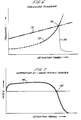
- the pressure in the air chamber 59 increases gradually, rising inversely with the reduction in the volume of the air chamber.
- the pressures in the two chambers 59 and 61 cross over as shown at 74 in Figure 6 so that the pressure in the air chamber thereafter exceeds that in the liquid chamber.
- the rib 79 at the lower end 29 of the lower portion 26 of the stem encounters the recess 78 the liquid pressure in liquid chamber 61 is released by escape of liquid via the recess and the pressure of liquid falls as indicated by curve 75 in Figure 6.
- the position of the recess 78 relative to the third cylinder 18 (or the position of rib 79 relative to the lower portion 26) can be varied to provide a desired position during the downstroke at which crossover occurs.
- Air released under pressure from the air chamber 59 then flows through the air conduit 50, out of the air exit port 55, through the actuator chamber 67 and out of the fluid discharge orifice 69 as shown in Figure 3. Liquid remaining in the actuator chamber 67 and discharge orifice 69 is purged from the actuator 65 by this flow of air.
- the dispenser 1 is then ready for re-use. During extended periods between successive actuations of the dispenser 1, the tendency for liquid in contact with ambient air to evaporate leaving undesirable residues is minimised since the actuator chamber 67 and discharge orifice 69 are purged with a flow of air at the end of each actuation. The dispenser 1 is therefore ready for re-use without the need for cleansing the actuator to remove any residue.
- the dispenser 1 is therefore suitable for use with water based formulations, particularly those containing a high percentage of solids.
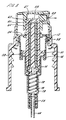
- An alternative dispenser 100 shown in Figure 8 is a modified version of the dispenser 1 of preceding Figures and will be described using corresponding references where appropriate for corresponding features.
- the dispenser 100 is similar to the dispenser 1 of preceding Figures in that it includes first and second pistons 41 and 45 which are slidable in respective cylinders 14 and 10 in order to pressurise volumes of liquid and air respectively within chambers 61 and 59.
- the dispenser 100 however has an air exit port 55 which is maintained permanently open by means of ribs 101 projecting outwardly of the upper end 60 of the first piston 41.
- the ribs 101 are circumferentially spaced about the upper end 60 so as to define therebetween air channels constituting the air exit port 55.
- the dispenser 100 has a second cylinder 10 having an upper end 2 which has the same internal cross-section as the remainder of the second cylinder such that in the rest position of the dispenser 1 in which the second piston is fully raised as shown in Figure 8 the outward extension 54 of the second piston continues to make peripheral sealing contact with the inner wall 47 of the second cylinder.
- Pressurised liquid is then forced out of the liquid chamber 61 via the liquid conduit 42, through the liquid exit port 57 into the actuator chamber 67 where it is turbulently mixed with the flow of air.
- the mixture of air and liquid then emerges from the fluid discharge orifice 69 as an atomised spray.
- Air suction created during the return stroke ensures that the actuator chamber 67 remains free of liquid between successive actuations thereby avoiding the build-up of residues caused by evaporation of the liquid which would otherwise lead to partial obstruction of the actuator or even total clogging.
- the flow of air from the air chamber 59 also serves to purge the actuator chamber 67 of liquid at the final portion of travel during the downstroke when the lower end 29 of the stem lower portion 26 encounters the recess 78 in the third cylinder 18. A sudden drop in liquid pressure at this point results in the flow of liquid being shut off whereas the flow of air continues through the actuator 65 thereby providing a purging action.
- the liquid exit port 57 is defined between the upper end 60 of the first piston 41 and the upper end 64 of the stem upper portion 24 and the air exit port 55 is defined between the upper end 60 of the first piston and the upper end 62 of the second piston. Consequently the air and liquid exit ports 55 and 57 are necessarily in close proximity so that liquid/air mixing commences immediately liquid exits the liquid exit port and also during the return stroke suction is applied in the vicinity of the liquid exit port thereby removing any residual liquid from this region.
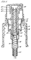
- a further alternative dispenser 120 is shown in Figure 9 and is described using corresponding reference numerals to those of preceding Figures where appropriate for corresponding features.
- the dispenser 120 differs from the dispenser 100 of Figure 8 in the configuration of the upper extension 40 of the first piston 41 and the upper section 48 of the second piston 45 and their relationship with the actuator 65.
- the upper extension 40 of first piston 41 extends upwardly beyond the upper end 62 of the second piston 45 and is sealingly received in the actuator 65.
- the upper extension 40 defines a vertically extending liquid passageway 121 communicating with the liquid conduit 42 via the liquid exit port 57.
- the upper section 40 of the first piston 41 is received as a snug fit within the upper section 48 of the second piston 45 so that in use there is no relative movement between the first and second pistons.
- the upper section 48 of the second piston 45 is provided with grooves facilitating air flow between the upper section 48 and the upper extension 40 so as to communicate between the air conduit 50 and the actuator chamber 67.
- the liquid exit port 57 opens during the downstroke of the dispenser 120 allowing a flow of pressurised liquid to pass through the liquid passageway 121 into the actuator chamber 67 where it is mixed with air delivered under pressure from the air chamber 59 via the air conduit 50.
- the air and liquid mix in the actuator chamber 67 and are dispensed from the fluid discharge orifice 69 as an atomised spray.
- the nozzle insert 68 is provided with swirl inducing grooves 122 extending non-radially from the periphery of the nozzle insert towards the centrally located fluid discharge orifice 69 so as to impart a swirling motion to the dispensed spray thereby assisting in the breakup of liquid droplets.
- a further dispenser 130 is shown in Figures 12 and 13 and is described using corresponding reference numerals to those of preceding Figures where appropriate for corresponding elements.
- the upper section 48 of the second piston 45 is sealingly engaged in the actuator 65 such that the hollow interior of the upper section communicates with the actuator chamber 67.
- the upper section 48 is formed with a radially inwardly projecting shoulder 131 which is engaged by a cooperating shoulder 132 formed externally on the upper extension 40 of the first piston 41 to thereby limit penetration of the first piston within the second piston 45.
- the upper end 60 of the first piston is provided with grooves to allow air to communicate between the air conduit 50 and the actuator chamber 67, the grooves thereby constituting a permanently open air exit port 55.
- the air exit port 55 is thereby located in close proximity with the liquid exit port 57.
- the actuator chamber 67 constitutes a vertically extending cylindrical volume in which air and liquid mix during the dispensing stroke. During the return stroke of the dispenser 130 any residual liquid in the region of the nozzle insert 68 and the orifice 69 is sucked back into the actuator chamber 67 and from there is drawn into the air conduit 50 to be collected in the air chamber 59.
- the location of the air exit port 55 is at the lowermost point of the actuator chamber 67 in which air and liquid are mixed so that residual liquid is efficiently extracted by suction during the return stroke.
- the air exit port 55 is also located in close proximity to the liquid exit port 57 so as to efficiently remove liquid from proximity with the liquid exit port during the return stroke.
- a further alternative dispenser 160 is shown in Figure 14 and is a modification of the dispenser 130 of Figures 12 and 13.
- the apparatus 160 has a porous plug 161 cooperating with a wide bore outlet duct 162 to produce foam when air and liquid are dispensed from the actuator chamber 67.
- the porous plug 161 is formed of wire mesh.
- a further alternative dispenser 140 is shown in Figures 15, 16 and 17 and will be described using corresponding reference numerals to those of preceding Figures where appropriate for corresponding elements.
- the dispenser 140 includes first and second pistons 41 and 45 having the same configuration as those of the dispenser 120 of Figure 9.
- the actuator 65 is however modified such that the upper extension 40 of the first piston 41 has an upwardly extending liquid passageway 121 communicating with a horizontally extending duct 141 defined by the actuator 65 and which is isolated from the flow of air into the actuator from the air conduit 50.
- the horizontal duct 141 communicates with a peripheral channel 142 defined by the nozzle insert 68 and communicating with swirl grooves 122 which in use allow liquid to flow from the peripheral channel through the grooves to a centrally positioned fluid discharge orifice 69 from which liquid is dispensed.
- the actuator 65 further defines a horizontally extending air duct 143 which is in line with the fluid discharge orifice 69 and communicates with the air conduit 50 such that in use a flow of air exits the orifice 69 by flowing directly through the air duct 143. Mixing of air and liquid takes place locally at the fluid discharge orifice 69.
- a further alternative dispenser 150 is shown in Figure 18 and is described using corresponding reference numerals to those of previous Figures for corresponding elements where appropriate.
- the dispenser 150 is similar to the dispenser 140 of Figure 15 but has a modified upper extension 40 to the first piston 41 in that it is shorter in length so as to project to a lesser extent into the actuator 65.
- the upper extension 40 defines a liquid passageway 121 which communicates with an actuator chamber 67 which in turn communicates with a horizontally extending duct 151 which is in line with and communicates with the fluid discharge orifice 69.
- the air conduit 50 extends peripherally of the upper extension 40 and is isolated from the actuator chamber 67.
- the air conduit 50 communicates instead with a peripheral channel 152 extending peripherally of the nozzle insert 68 and communicating with swirl grooves 122 delivering air from the air conduit 50 to the fluid discharge orifice 69. Mixing of air and liquid in use occurs locally at the orifice 69.
- the actuating means is constituted by an actuator 65 of the button type which is manually depressed by finger pressure.
- Alternative embodiments may include a trigger mechanism in which movement of a trigger is coupled to movement of the pistons 41 and 45 by lever action to provide mechanical advantage or for convenience.
Landscapes
- Physics & Mathematics (AREA)
- Fluid Mechanics (AREA)
- General Physics & Mathematics (AREA)
- Containers And Packaging Bodies Having A Special Means To Remove Contents (AREA)
- Nozzles (AREA)
- Medicines That Contain Protein Lipid Enzymes And Other Medicines (AREA)
- Catching Or Destruction (AREA)
Claims (16)
- Abgabevorrichtung (1) zur Abgabe von Flüssigkeit als zerstäubtes Spray durch Pumpwirkung, wobei die Vorrichtung umfaßt: einen Körper (71), der einen ersten Zylinder (14) festlegt, innerhalb welchem ein erster Kolben (41) hin- und herbewegbar angeordnet ist, um eine erste Kammer (61) von veränderlichem Volumen festzulegen, die bei Verwendung eine Menge von abzugebender Flüssigkeit enthält;
einen zweiten Zylinder (10) mit einem zweiten Kolben (45), um eine zweite Kammer (59) von veränderlichem Volumen festzulegen, die bei Verwendung eine Menge an Luft enthält;
Betätigungsmittel (65), die während eines Betätigungshubs betriebsfähig sind, um zwischen den Kolben und jeweiligen Zylindern eine Relativbewegung in Richtungen zu bewirken, so daß die Volumina der jeweiligen Kammern reduziert werden, und während eines Rückkehrhubs betriebsfähig sind, um eine Rückkehrbewegung in jeweilige Ruhepositionen zu bewirken, in denen die jeweiligen Kammern expandiert sind;
Flüssigkeitsventilmittel (28, 30, 60, 64), welche betriebsfähig sind, um während wenigstens einem Teil des Rückkehrhubs Flüssigkeit in die erste Kammer einzulassen und während wenigstens einem Teil des Betätigungshubs unter Druck stehende Flüssigkeit aus dieser freizugeben, wobei die Flüssigkeitsventilmittel eine Flüssigkeitsautrittsöffnung (43) zur Abgabe von Flüssigkeit aus der ersten Kammer umfassen;
Kanalmittel, die eine Abflußöffnung (69) und einen Abgabekanal (67) festlegen, der zwischen der Flüssigkeitsautrittsöffnung und der Abflußöffnung in Verbindung steht,
und Luftleitungsmittel (41, 48), die eine Luftleitung (50) festlegen, die während wenigstens einem Teil des Betätigungshubs zwischen der zweiten Kammer und dem Abgabekanal in Verbindung steht, wodurch bei Verwendung unter Druck gesetzte Luft in der zweiten Kammer über den Kanal durch die Abflußöffnung geleitet wird,
dadurch gekennzeichnet,
daß der zweite Zylinder integral in koaxialer Ausrichtung mit dem ersten Zylinder als Teil des Körpers gebildet ist. - Abgabevorrichtung nach Anspruch 1, bei welcher sich der zweite Zylinder zwischen dem ersten Zylinder und den Betätigungsmitteln befindet und bei welcher der zweite Kolben einen hohlen oberen Fortsatz (48) umfaßt, durch welchen sich ein hohler oberer Fortsatz (40) des ersten Kolbens erstreckt, wobei der erste und zweite Kolben derart ineinandergesteckt sind, daß sie durch die Bewegung der Betätigungsmittel im wesentlichen gemeinsam relativ zu dem Körper axial verlagert werden.
- Abgabevorrichtung nach Anspruch 2, bei welcher die Flüssigkeitsventilmittel betriebsfähig sind, um die Flüssigkeitsautrittsöffnung vor Beendigung des Betätigungshubs zu schließen derart, daß während eines Endabschnitts des Betätigungshubs die Freigabe von Flüssigkeit aus der ersten Kammer angehalten ist.
- Abgabevorrichtung nach Anspruch 3, bei welcher die Flüssigkeitsautrittsöffnung in Antwort auf eine Zunahme im Flüssigkeitsdruck innerhalb der ersten Kammer geöffnet wird, wobei die Vorrichtung ferner Druckentlastungsmittel (78) umfaßt, welche betriebsfähig sind, um den Flüssigkeitsdruck in der ersten Kammer während des Endabschnitts des Betätigungshubs zu vermindern, um dadurch eine Schließung der Flüssigkeitsventilmittel zu bewirken.
- Abgabevorrichtung nach Anspruch 4, bei welcher die Flüssigkeitsventilmittel einen länglichen Schaft (24, 26) umfassen, welcher einen oberen Abschnitt (24) aufweist, der sich in den hohlen oberen Fortsatz (40) des ersten Kolbens erstreckt und in und außer Eingriff mit dem ersten Kolben bewegbar ist, um die Flüssigkeitsautrittsöffnung zu schließen bzw. zu öffnen, sowie einen unteren Abschnitt (26), der sich durch den ersten Zylinder erstreckt und ein unteres Ende (29) umfaßt, welches am Umfang mit einer Innenfläche (9) des Körpers in Eingriff bringbar ist, und dadurch die erste Kammer normalerweise schließt, wobei die Fläche mit einer Ausnehmung (78) versehen ist, um zu ermöglichen, daß Flüssigkeit während des Endabschnitts des Betätigungshubs das untere Ende umgeht, um dadurch die Druckentlastungsmittel zu bilden.
- Abgabevorrichtung nach einem der vorhergehenden Ansprüche, ferner umfassend Luftventilmittel (60, 62), welche betriebsfähig sind, um unter Druck gesetzte Luft in der zweiten Kammer freizugeben und welche eine Luftaustrittsöffnung umfassen, die mit dem Abgabekanal in Verbindung steht, wobei die Luftventilmittel derart betriebsfähig sind, daß die Luftaustrittsöffnung während wenigstens eines Teils des Betätigungshubs offen sind und während dem Rückkehrhub geschlossen sind.
- Abgabevorrichtung nach Anspruch 6, bei welcher die Luftventilmittel und die Flüssigkeitsventilmittel derart zusammenwirken können, daß bei Beginn des Endabschnitts des Betätigungshubs die Flüssigkeitsautrittsöffnung schließt und die Luftaustrittsöffnung öffnet.
- Abgabevorrichtung nach einem der Ansprüche 6 und 7, bei welcher die Luftaustrittsöffnung zwischen einem ringförmigen oberen Endabschnitt (60) des hohlen oberen Fortsatzes (40) des ersten Kolbens und einer Innenwand des hohlen oberen Fortsatzes (48) des zweiten Kolbens festgelegt ist, die relativ bewegbar sind, um die Luftaustrittsöffnung zu öffnen und zu schließen und dadurch die Luftventilmittel bilden.
- Abgabevorrichtung nach Anspruch 8, bei welcher die Flüssigkeitsautrittsöffnung durch den ringförmigen oberen Endabschnitt des ersten Kolbens festgelegt ist, wobei sich die Luftaustrittsöffnung unmittelbar benachbart zu der Flüssigkeitsautrittsöffnung befindet.
- Abgabevorrichtung nach einem der Ansprüche 6 bis 9, bei welcher die Luftventilmittel ferner eine Lufteintrittsöffnung (53) umfassen, die mit der zweiten Kammer in Verbindung steht und die am Ende des Rückkehrhubs geöffnet wird, um Luft in die zweite Kammer einzulassen.
- Abgabevorrichtung nach Anspruch 1, bei welcher die Luftleitungsmittel eine Luftleitung (50) umfassen, die durch den hohlen oberen Fortsatz (48) des zweiten Kolbens festgelegt ist und kontinuierlich über eine kontinuierlich offene Luftaustrittsöffnung (55) mit dem Abgabekanal in Verbindung steht, wodurch Luft während des Rückkehrhubs über den Abgabekanal in die zweite Kammer tritt.
- Abgabevorrichtung nach Anspruch 11, bei welcher die Luftaustrittsöffnung zwischen einem ringförmigen oberen Ende (60) des hohlen oberen Fortsatzes (40) des ersten Kolbens und einer Innenwand des hohlen oberen Abschnitts (48) des zweiten Kolbens festgelegt ist, wobei die Flüssigkeitsautrittsöffnung (57) durch den ringförmigen oberen Endabschnitt des hohlen oberen Fortsatzes (40) des ersten Kolbens festgelegt ist, wobei sich die Luftaustrittsöffnung unmittelbar benachbart zu der Flüssigkeitsautrittsöffnung befindet.
- Abgabevorrichtung nach einem der Ansprüche 11 und 12, bei welcher die Kanalmittel eine Mischkammer (67) festlegen, die sich stromabwärts sowohl der Luftaustrittsöffnung als auch der Flüssigkeitsaustrittsöffnung befindet, wobei sich die Mischkammer stromaufwärts der Abflußöffnung befindet, wodurch Luft und Flüssigkeit vor Abgabe gemischt werden.
- Abgabevorrichtung nach Anspruch 1, bei welcher die Kanalmittel einen Luftkanal und einen Flüssigkeitskanal (121) umfassen, der separat von dem Luftkanal gebildet ist, wobei sich der Luftkanal und der Flüssigkeitskanal von ihrer Luft- bzw. Flüssigkeitsautrittsöffnung zu einem Ort unmittelbar benachbart zu der Abflußöffnung erstrecken, wo sie verbunden sind, um ein Mischen von Luft und Flüssigkeit unmittelbar vor der Abgabe vorzusehen.
- Abgabevorrichtung nach Anspruch 14, bei welcher sich wenigstens ein Endabschnitt (151) des Flüssigkeitskanals linear in Flucht mit der Abgabeöffnung erstreckt.
- Abgabevorrichtung nach Anspruch 11, bei welcher die Kanalmittel einen Betätigungsknopf (65) umfassen, der mit den Kolben zusammenwirkt, um den Abgabekanal (67) festzulegen, wobei der Betätigungsknopf manuell derart verlagerbar ist, daß er den ersten und zweiten Kolben während des Betätigungshubs relativ zu dem Körper bewegt.
Applications Claiming Priority (2)
| Application Number | Priority Date | Filing Date | Title |
|---|---|---|---|
| US08/025,407 US5348189A (en) | 1991-04-10 | 1993-02-26 | Air purge pump dispenser |
| US25407 | 2001-12-19 |
Publications (3)
| Publication Number | Publication Date |
|---|---|
| EP0618147A2 EP0618147A2 (de) | 1994-10-05 |
| EP0618147A3 EP0618147A3 (de) | 1994-12-28 |
| EP0618147B1 true EP0618147B1 (de) | 1997-05-07 |
Family
ID=21825881
Family Applications (1)
| Application Number | Title | Priority Date | Filing Date |
|---|---|---|---|
| EP93306716A Expired - Lifetime EP0618147B1 (de) | 1993-02-26 | 1993-08-24 | Selbstreinigender Luftpumpenspender |
Country Status (7)
| Country | Link |
|---|---|
| US (1) | US5348189A (de) |
| EP (1) | EP0618147B1 (de) |
| JP (1) | JPH06254445A (de) |
| CN (1) | CN1052206C (de) |
| AT (1) | ATE152686T1 (de) |
| DE (1) | DE69310496T2 (de) |
| ES (1) | ES2101236T3 (de) |
Cited By (2)
| Publication number | Priority date | Publication date | Assignee | Title |
|---|---|---|---|---|
| EP0984715B2 (de) † | 1998-03-30 | 2010-01-13 | Deb IP Limited | Flüssigkeitsspender zur erzeugung von schaum |
| US8261950B2 (en) | 2007-10-22 | 2012-09-11 | Georgia-Pacific Consumer Products Lp | Pumping dispenser |
Families Citing this family (86)
| Publication number | Priority date | Publication date | Assignee | Title |
|---|---|---|---|---|
| US7628339B2 (en) | 1991-04-24 | 2009-12-08 | Novartis Pharma Ag | Systems and methods for controlling fluid feed to an aerosol generator |
| US6540154B1 (en) | 1991-04-24 | 2003-04-01 | Aerogen, Inc. | Systems and methods for controlling fluid feed to an aerosol generator |
| US5458289A (en) * | 1993-03-01 | 1995-10-17 | Bespak Plc | Liquid dispensing apparatus with reduced clogging |
| US5445288A (en) * | 1994-04-05 | 1995-08-29 | Sprintvest Corporation Nv | Liquid dispenser for dispensing foam |
| FR2719789B1 (fr) * | 1994-05-10 | 1996-07-05 | Saint Laurent Parfums Yves | Dispositif de distribution d'un produit en mélange avec un fluide, ensemble de distribution comprenant un tel dispositif. |
| US5664706A (en) * | 1994-10-13 | 1997-09-09 | Bespak Plc | Apparatus for dispensing liquid in aerosol spray form |
| US6085740A (en) | 1996-02-21 | 2000-07-11 | Aerogen, Inc. | Liquid dispensing apparatus and methods |
| US6782886B2 (en) | 1995-04-05 | 2004-08-31 | Aerogen, Inc. | Metering pumps for an aerosolizer |
| US5758637A (en) | 1995-08-31 | 1998-06-02 | Aerogen, Inc. | Liquid dispensing apparatus and methods |
| US6050457A (en) * | 1995-12-06 | 2000-04-18 | The Procter & Gamble Company | High pressure manually-actuated spray pump |
| USD396188S (en) | 1996-02-23 | 1998-07-21 | Owens-Illinois Closure Inc. | Liquid dispenser |
| US5785208A (en) * | 1996-04-10 | 1998-07-28 | Calmar Inc. | Precompression pump sprayer having suck-back feature |
| DE19623030A1 (de) * | 1996-06-08 | 1997-12-11 | Pfeiffer Erich Gmbh & Co Kg | Austrag-Einheit für Medien |
| WO1998025111A1 (es) * | 1996-12-05 | 1998-06-11 | Olegnowicz W Jaime | Bomba mecanica impelente de liquidos en forma atomizada, con medios de sello no deslizantes |
| ES2149066B1 (es) * | 1997-04-17 | 2001-05-01 | Bravo Casado Juan | Perfeccionamientos introducidos en la fabricacion de valvulas, de las conocidas como "de bola", destinadas al suministro de toda clase de liquidos. |
| USD441654S1 (en) | 1997-04-18 | 2001-05-08 | Owens-Illinois Closure Inc. | Liquid dispenser |
| DE19723134A1 (de) * | 1997-06-03 | 1998-12-10 | Pfeiffer Erich Gmbh & Co Kg | Austragvorrichtung für Medien |
| US5839617A (en) * | 1997-07-29 | 1998-11-24 | Owens-Illinois Closure Inc. | Pump dispenser |
| GB2337460B (en) * | 1998-05-20 | 2002-12-18 | Susan Ayton | Improvements in or relating to depilatory methods |
| DE19845910A1 (de) * | 1998-10-06 | 2000-04-13 | Pfeiffer Erich Gmbh & Co Kg | Spender für Medien |
| USD419877S (en) * | 1998-12-03 | 2000-02-01 | Owens-Illinois Closure Inc. | Liquid dispenser |
| USD414696S (en) | 1998-12-03 | 1999-10-05 | Owens-Illinois Closure Inc. | Liquid dispenser |
| USD414697S (en) | 1998-12-03 | 1999-10-05 | Owens-Illinois Closure Inc. | Liquid dispenser |
| NL1012419C2 (nl) * | 1999-06-23 | 2000-12-28 | Airspray Nv | Spuitbus voor het afgeven van een vloeistof. |
| US6158625A (en) * | 1999-08-17 | 2000-12-12 | Calmar Inc. | Anti-clog pump sprayer |
| US6235177B1 (en) | 1999-09-09 | 2001-05-22 | Aerogen, Inc. | Method for the construction of an aperture plate for dispensing liquid droplets |
| US6494349B1 (en) | 1999-11-17 | 2002-12-17 | The Gillette Company | Hand-held product dispensers having pressurized delivery |
| EP1118389A1 (de) * | 2000-01-19 | 2001-07-25 | Cws International Ag | Verfahren und Vorrichtung zur kontrollierten Schaumabgabe |
| US7100600B2 (en) | 2001-03-20 | 2006-09-05 | Aerogen, Inc. | Fluid filled ampoules and methods for their use in aerosolizers |
| US6948491B2 (en) | 2001-03-20 | 2005-09-27 | Aerogen, Inc. | Convertible fluid feed system with comformable reservoir and methods |
| MXPA02010884A (es) | 2000-05-05 | 2003-03-27 | Aerogen Ireland Ltd | Aparato y metodo para el suministro de medicamentos al sistema respiratorio. |
| US8336545B2 (en) | 2000-05-05 | 2012-12-25 | Novartis Pharma Ag | Methods and systems for operating an aerosol generator |
| US7971588B2 (en) | 2000-05-05 | 2011-07-05 | Novartis Ag | Methods and systems for operating an aerosol generator |
| US7600511B2 (en) | 2001-11-01 | 2009-10-13 | Novartis Pharma Ag | Apparatus and methods for delivery of medicament to a respiratory system |
| FR2810645B1 (fr) * | 2000-06-22 | 2002-10-25 | Valois Sa | Dispositif de distribution de produit fluide |
| US6446880B1 (en) | 2000-08-02 | 2002-09-10 | S.C. Johnson & Son, Inc. | Replaceable reservoir for an atomizing apparatus |
| US6612468B2 (en) | 2000-09-15 | 2003-09-02 | Rieke Corporation | Dispenser pumps |
| FR2815611B1 (fr) * | 2000-10-23 | 2003-04-11 | Valois Sa | Tete de distribution et distributeur de produit fluide comportant une telle tete de distribution |
| US6536685B2 (en) * | 2001-03-16 | 2003-03-25 | Unilever Home And Personal Care Usa, Division Of Conopco, Inc. | Foamer |
| JP3942020B2 (ja) † | 2002-05-23 | 2007-07-11 | 株式会社吉野工業所 | 蓄圧式ポンプおよびそのモジュール |
| US6732944B2 (en) | 2001-05-02 | 2004-05-11 | Aerogen, Inc. | Base isolated nebulizing device and methods |
| NL1019348C2 (nl) * | 2001-11-12 | 2003-05-13 | Bentfield Europ Bv | Schuimdispenser, huis en voorraadhouder daarvoor. |
| NL1020641C2 (nl) | 2001-11-12 | 2003-05-15 | Bentfield Europ Bv | Dispenser voor afgifte van een vloeistof en huis voor een dergelijke dispenser. |
| FR2832079B1 (fr) * | 2001-11-14 | 2004-07-30 | Valois Sa | Tete de distribution et distributeur de produit fluide comportant une telle tete de distribution |
| EP1471960B1 (de) | 2002-01-07 | 2019-03-13 | Novartis AG | Vorrichtungen zur vernebelung von flüssigkeiten zur inhalation |
| US7677467B2 (en) | 2002-01-07 | 2010-03-16 | Novartis Pharma Ag | Methods and devices for aerosolizing medicament |
| EP1474196B1 (de) | 2002-01-15 | 2016-08-17 | Novartis AG | Verfahren und systeme zum bedienen eines aerosol-erzeugers |
| AU2003256253A1 (en) | 2002-05-20 | 2003-12-02 | Aerogen, Inc. | Aerosol for medical treatment and methods |
| US6644516B1 (en) * | 2002-11-06 | 2003-11-11 | Continental Afa Dispensing Company | Foaming liquid dispenser |
| US20040188473A1 (en) * | 2003-03-25 | 2004-09-30 | Groh David M. | Hand-held product dispensers having pressurized delivery |
| USD515920S1 (en) | 2003-03-25 | 2006-02-28 | The Gillette Company | Hand held product dispenser |
| US8616195B2 (en) | 2003-07-18 | 2013-12-31 | Novartis Ag | Nebuliser for the production of aerosolized medication |
| US7004356B1 (en) * | 2003-07-28 | 2006-02-28 | Joseph S. Kanfer | Foam producing pump with anti-drip feature |
| NL1024350C2 (nl) | 2003-09-23 | 2005-03-24 | R & D Injector Ag | Afgifte-eenheid voor geconcentreerd injecteren. |
| US7290541B2 (en) | 2004-04-20 | 2007-11-06 | Aerogen, Inc. | Aerosol delivery apparatus and method for pressure-assisted breathing systems |
| US7267121B2 (en) | 2004-04-20 | 2007-09-11 | Aerogen, Inc. | Aerosol delivery apparatus and method for pressure-assisted breathing systems |
| US7946291B2 (en) | 2004-04-20 | 2011-05-24 | Novartis Ag | Ventilation systems and methods employing aerosol generators |
| FR2879567B1 (fr) * | 2004-12-17 | 2007-01-26 | Seriplast Sa Sa | Flacon en matiere synthetique equipe d'une pompe |
| US7802701B2 (en) | 2005-01-14 | 2010-09-28 | Rieke Corporation | Up-lock seal for dispenser pump |
| NL1028827C2 (nl) * | 2005-04-20 | 2006-10-23 | Keltec B V | Afgifte-eenheid. |
| CA2504989C (en) * | 2005-04-22 | 2013-03-12 | Gotohti.Com Inc. | Stepped pump foam dispenser |
| US7770874B2 (en) * | 2005-04-22 | 2010-08-10 | Gotohii.com Inc. | Foam pump with spring |
| CA2791887C (en) * | 2005-04-22 | 2014-10-07 | Gotohti.Com Inc. | Foam pump with bellows spring |
| US7337930B2 (en) * | 2005-05-20 | 2008-03-04 | Gotohti.Com Inc. | Foaming pump with improved air inlet valve |
| BRPI0611198B1 (pt) | 2005-05-25 | 2018-02-06 | Aerogen, Inc. | Vibration systems and methods |
| FR2893314B1 (fr) * | 2005-11-16 | 2007-12-21 | Rexam Dispensing Smt Soc Par A | Tete d'actionnement et de distribution pour pompe |
| WO2009038452A1 (en) * | 2007-09-17 | 2009-03-26 | Rexam Airspray N.V. | Foam dispensing assembly |
| FR2933679B1 (fr) * | 2008-07-10 | 2010-09-03 | Valois Sas | Dispositif de distribution de produit fluide. |
| MX2012000698A (es) * | 2009-07-15 | 2012-03-07 | Procter & Gamble | Bomba dispensadora con tubo de inmersion que tiene una porcion de punta mas ancha. |
| WO2011133077A1 (en) | 2010-04-22 | 2011-10-27 | Sca Hygiene Products Ab | Pump soap dispenser |
| EP2484454B1 (de) * | 2011-02-02 | 2014-05-14 | Dispensys AG | Austragvorrichtung für fließfähigen Stoff |
| JP5873247B2 (ja) * | 2011-03-22 | 2016-03-01 | 大和製罐株式会社 | ポンプ式泡吐出容器 |
| US8651328B2 (en) | 2011-07-14 | 2014-02-18 | Georgia-Pacific Consumer Products Lp | Pumping dispenser shield |
| US8814005B2 (en) | 2012-04-27 | 2014-08-26 | Pibed Limited | Foam dispenser |
| FR2990931B1 (fr) * | 2012-05-23 | 2015-07-24 | Rexam Dispensing Sys | Systeme de distribution d’un produit fluide |
| US9220377B2 (en) * | 2012-08-02 | 2015-12-29 | Rubbermaid Commercial Products, Llc | Foam dispensing pump with decompression feature |
| KR102128801B1 (ko) * | 2013-01-31 | 2020-07-01 | 가부시키가이샤 요시노 고교쇼 | 거품 토출기 |
| JP6328418B2 (ja) * | 2013-12-19 | 2018-05-23 | 株式会社ダイゾー | エアゾール製品 |
| CA2837774A1 (en) | 2013-12-20 | 2015-06-20 | Heiner Ophardt | Piston pump with vacuum relief |
| RU2674873C2 (ru) | 2014-05-12 | 2018-12-13 | Деб АйПи Лимитед | Улучшенный пенный насос |
| US10034583B2 (en) | 2016-03-04 | 2018-07-31 | Gpcp Ip Holdings Llc | Dispenser with stroke adjustment capabilities |
| FR3065653B1 (fr) * | 2017-04-27 | 2021-10-22 | Aptar France Sas | Tete de distribution de produit fluide. |
| ES2879863T3 (es) * | 2017-04-27 | 2021-11-23 | Aptar France Sas | Cabezal de dispensación de producto fluido |
| IT201700056451A1 (it) * | 2017-05-24 | 2018-11-24 | Lumson Spa | Contenitore di sostanze fluide con sistema di chiusura ermetica e metodo di utilizzo |
| FR3068624B1 (fr) * | 2017-07-06 | 2021-01-22 | Aptar France Sas | Dispositif de distribution de produit fluide. |
| EP4263065B1 (de) * | 2020-12-15 | 2024-07-17 | Unilever IP Holdings B.V. | Sprühspender |
Family Cites Families (17)
| Publication number | Priority date | Publication date | Assignee | Title |
|---|---|---|---|---|
| US4057176A (en) * | 1975-07-18 | 1977-11-08 | Plastic Research Products, Inc. | Manually operated spray pump |
| IT7620983U1 (it) * | 1976-03-16 | 1977-09-16 | Coster Tecnologie Speciali Spa | Valvola dosatrice per aerosol ad effetto pompante. |
| US4274560A (en) * | 1976-04-30 | 1981-06-23 | Emson Research Incorporated | Atomizing pump dispenser |
| US4089442A (en) * | 1976-09-30 | 1978-05-16 | Ethyl Corporation | Accumulative pressure pump |
| DE2825428A1 (de) * | 1978-06-09 | 1979-12-13 | Seltmann Hans Juergen | Ausgabepumpe, insbesondere zum zerstaeuben von fluessigkeiten |
| US4230242A (en) * | 1979-03-26 | 1980-10-28 | Philip Meshberg | Triple seal valve member for an atomizing pump dispenser |
| DE3315334A1 (de) * | 1983-04-28 | 1984-10-31 | Pfeiffer Erich Gmbh & Co Kg | Zerstaeuber- oder dosierpumpe |
| DE3517558A1 (de) * | 1985-05-15 | 1986-11-20 | Ing. Erich Pfeiffer GmbH & Co KG, 7760 Radolfzell | Handbetaetigte ausgabeeinrichtung fuer medien |
| US4735347A (en) * | 1985-05-28 | 1988-04-05 | Emson Research, Inc. | Single puff atomizing pump dispenser |
| DE3722470A1 (de) * | 1987-07-08 | 1989-01-19 | Pfeiffer Erich Gmbh & Co Kg | Handbetaetigbare austragvorrichtung fuer medien |
| NL8702225A (nl) * | 1987-09-17 | 1989-04-17 | Maria Musilova | Dubbel-effectieve kleine pomp met verstuiveropzetstuk voor spuitflessen. |
| FR2652389B1 (fr) * | 1989-09-26 | 1992-12-04 | Debard Andre | Perfectionnement aux pompes a precompression pour la diffusion d'un liquide. |
| DE4011537A1 (de) * | 1990-04-10 | 1991-10-17 | Pfeiffer Erich Gmbh & Co Kg | Austragvorrichtung fuer mindestens ein medium |
| ES2024213A6 (es) * | 1990-04-26 | 1992-02-16 | Monturas Sa | Perfeccionamientos en el objeto de la patente de invencion 88 03075 por bomba pulverizadora. |
| US5100029A (en) * | 1990-05-22 | 1992-03-31 | Philip Meshberg | Self-purging actuator |
| US5147073A (en) * | 1991-02-11 | 1992-09-15 | Spruhventile Gmbh | Fluid pump dispenser for pharmaceutical use |
| US5163588A (en) * | 1991-04-10 | 1992-11-17 | Bespak Plc | Atomizing pump dispenser for water based formulations |
-
1993
- 1993-02-26 US US08/025,407 patent/US5348189A/en not_active Expired - Fee Related
- 1993-08-24 EP EP93306716A patent/EP0618147B1/de not_active Expired - Lifetime
- 1993-08-24 DE DE69310496T patent/DE69310496T2/de not_active Expired - Fee Related
- 1993-08-24 AT AT93306716T patent/ATE152686T1/de active
- 1993-08-24 ES ES93306716T patent/ES2101236T3/es not_active Expired - Lifetime
- 1993-10-28 CN CN93119432A patent/CN1052206C/zh not_active Expired - Fee Related
- 1993-12-03 JP JP5303935A patent/JPH06254445A/ja active Pending
Cited By (3)
| Publication number | Priority date | Publication date | Assignee | Title |
|---|---|---|---|---|
| EP0984715B2 (de) † | 1998-03-30 | 2010-01-13 | Deb IP Limited | Flüssigkeitsspender zur erzeugung von schaum |
| US8261950B2 (en) | 2007-10-22 | 2012-09-11 | Georgia-Pacific Consumer Products Lp | Pumping dispenser |
| US8746510B2 (en) | 2007-10-22 | 2014-06-10 | Georgia-Pacific Consumer Products Lp | Pumping dispenser |
Also Published As
| Publication number | Publication date |
|---|---|
| ES2101236T3 (es) | 1997-07-01 |
| CN1052206C (zh) | 2000-05-10 |
| US5348189A (en) | 1994-09-20 |
| DE69310496T2 (de) | 1997-10-16 |
| DE69310496D1 (de) | 1997-06-12 |
| ATE152686T1 (de) | 1997-05-15 |
| CN1103012A (zh) | 1995-05-31 |
| EP0618147A2 (de) | 1994-10-05 |
| JPH06254445A (ja) | 1994-09-13 |
| EP0618147A3 (de) | 1994-12-28 |
Similar Documents
| Publication | Publication Date | Title |
|---|---|---|
| EP0618147B1 (de) | Selbstreinigender Luftpumpenspender | |
| US5458289A (en) | Liquid dispensing apparatus with reduced clogging | |
| US4986453A (en) | Atomizing pump | |
| EP0613727A1 (de) | Abgabevorrichtung | |
| US5785208A (en) | Precompression pump sprayer having suck-back feature | |
| US7066359B2 (en) | Dispenser for the discharge of flowable media | |
| AU705669B2 (en) | Improved two-phase dispensing systems utilizing bellows pumps | |
| US8205809B2 (en) | Atomizing foam pump | |
| CN102791385A (zh) | 手动泵型流体分配器 | |
| CA2613785A1 (en) | Angled slot foam dispenser | |
| WO2017029466A1 (en) | Spray nozzle arrangements | |
| EP0031930A1 (de) | Pumpe mit Druckspeicherung | |
| JPH06171678A (ja) | 噴霧分与装置 | |
| US5358149A (en) | Pressure build-up pump sprayer having anti-clogging means | |
| WO2009130462A1 (en) | Manual pump type fluid dispenser | |
| US20190151875A1 (en) | Fluid dispenser | |
| JP2014519969A (ja) | 種々の分注装置及びプラットホーム(フレアフレッシュ)における製品と噴射剤の隔離 | |
| US8028863B2 (en) | Fluid dispenser member | |
| US5265771A (en) | Self-purging actuator | |
| WO2009050449A1 (en) | A manual pump dispenser | |
| CA1323618C (en) | Atomizing pump | |
| EP4263065B1 (de) | Sprühspender | |
| JP3452283B2 (ja) | トリガー式噴霧器 | |
| JP2024095017A (ja) | 液体噴出器 | |
| JPH10316157A (ja) | ディスペンサー |
Legal Events
| Date | Code | Title | Description |
|---|---|---|---|
| PUAI | Public reference made under article 153(3) epc to a published international application that has entered the european phase |
Free format text: ORIGINAL CODE: 0009012 |
|
| AK | Designated contracting states |
Kind code of ref document: A2 Designated state(s): AT BE CH DE DK ES FR GB GR IE IT LI NL |
|
| PUAL | Search report despatched |
Free format text: ORIGINAL CODE: 0009013 |
|
| AK | Designated contracting states |
Kind code of ref document: A3 Designated state(s): AT BE CH DE DK ES FR GB GR IE IT LI NL |
|
| 17P | Request for examination filed |
Effective date: 19950105 |
|
| 17Q | First examination report despatched |
Effective date: 19960313 |
|
| GRAG | Despatch of communication of intention to grant |
Free format text: ORIGINAL CODE: EPIDOS AGRA |
|
| GRAH | Despatch of communication of intention to grant a patent |
Free format text: ORIGINAL CODE: EPIDOS IGRA |
|
| GRAH | Despatch of communication of intention to grant a patent |
Free format text: ORIGINAL CODE: EPIDOS IGRA |
|
| GRAA | (expected) grant |
Free format text: ORIGINAL CODE: 0009210 |
|
| AK | Designated contracting states |
Kind code of ref document: B1 Designated state(s): AT BE CH DE DK ES FR GB GR IE IT LI NL |
|
| PG25 | Lapsed in a contracting state [announced via postgrant information from national office to epo] |
Ref country code: NL Free format text: LAPSE BECAUSE OF FAILURE TO SUBMIT A TRANSLATION OF THE DESCRIPTION OR TO PAY THE FEE WITHIN THE PRESCRIBED TIME-LIMIT Effective date: 19970507 Ref country code: LI Effective date: 19970507 Ref country code: GR Free format text: LAPSE BECAUSE OF FAILURE TO SUBMIT A TRANSLATION OF THE DESCRIPTION OR TO PAY THE FEE WITHIN THE PRESCRIBED TIME-LIMIT Effective date: 19970507 Ref country code: DK Effective date: 19970507 Ref country code: CH Effective date: 19970507 Ref country code: BE Effective date: 19970507 Ref country code: AT Effective date: 19970507 |
|
| REF | Corresponds to: |
Ref document number: 152686 Country of ref document: AT Date of ref document: 19970515 Kind code of ref document: T |
|
| REG | Reference to a national code |
Ref country code: CH Ref legal event code: EP |
|
| ITF | It: translation for a ep patent filed | ||
| REF | Corresponds to: |
Ref document number: 69310496 Country of ref document: DE Date of ref document: 19970612 |
|
| ET | Fr: translation filed | ||
| REG | Reference to a national code |
Ref country code: ES Ref legal event code: FG2A Ref document number: 2101236 Country of ref document: ES Kind code of ref document: T3 |
|
| REG | Reference to a national code |
Ref country code: IE Ref legal event code: FG4D Free format text: 73799 |
|
| PG25 | Lapsed in a contracting state [announced via postgrant information from national office to epo] |
Ref country code: IE Free format text: LAPSE BECAUSE OF NON-PAYMENT OF DUE FEES Effective date: 19970824 |
|
| NLV1 | Nl: lapsed or annulled due to failure to fulfill the requirements of art. 29p and 29m of the patents act | ||
| REG | Reference to a national code |
Ref country code: CH Ref legal event code: PL |
|
| PLBE | No opposition filed within time limit |
Free format text: ORIGINAL CODE: 0009261 |
|
| STAA | Information on the status of an ep patent application or granted ep patent |
Free format text: STATUS: NO OPPOSITION FILED WITHIN TIME LIMIT |
|
| 26N | No opposition filed | ||
| PGFP | Annual fee paid to national office [announced via postgrant information from national office to epo] |
Ref country code: GB Payment date: 20010615 Year of fee payment: 9 |
|
| PGFP | Annual fee paid to national office [announced via postgrant information from national office to epo] |
Ref country code: FR Payment date: 20010626 Year of fee payment: 9 |
|
| PGFP | Annual fee paid to national office [announced via postgrant information from national office to epo] |
Ref country code: DE Payment date: 20010629 Year of fee payment: 9 |
|
| PGFP | Annual fee paid to national office [announced via postgrant information from national office to epo] |
Ref country code: ES Payment date: 20010808 Year of fee payment: 9 |
|
| REG | Reference to a national code |
Ref country code: GB Ref legal event code: IF02 |
|
| PG25 | Lapsed in a contracting state [announced via postgrant information from national office to epo] |
Ref country code: GB Free format text: LAPSE BECAUSE OF NON-PAYMENT OF DUE FEES Effective date: 20020824 |
|
| PG25 | Lapsed in a contracting state [announced via postgrant information from national office to epo] |
Ref country code: ES Free format text: LAPSE BECAUSE OF NON-PAYMENT OF DUE FEES Effective date: 20020825 |
|
| PG25 | Lapsed in a contracting state [announced via postgrant information from national office to epo] |
Ref country code: DE Free format text: LAPSE BECAUSE OF NON-PAYMENT OF DUE FEES Effective date: 20030301 |
|
| GBPC | Gb: european patent ceased through non-payment of renewal fee |
Effective date: 20020824 |
|
| PG25 | Lapsed in a contracting state [announced via postgrant information from national office to epo] |
Ref country code: FR Free format text: LAPSE BECAUSE OF NON-PAYMENT OF DUE FEES Effective date: 20030430 |
|
| REG | Reference to a national code |
Ref country code: FR Ref legal event code: ST |
|
| REG | Reference to a national code |
Ref country code: ES Ref legal event code: FD2A Effective date: 20030912 |
|
| PG25 | Lapsed in a contracting state [announced via postgrant information from national office to epo] |
Ref country code: IT Free format text: LAPSE BECAUSE OF NON-PAYMENT OF DUE FEES Effective date: 20050824 |