US6158625A - Anti-clog pump sprayer - Google Patents
Anti-clog pump sprayer Download PDFInfo
- Publication number
- US6158625A US6158625A US09/375,432 US37543299A US6158625A US 6158625 A US6158625 A US 6158625A US 37543299 A US37543299 A US 37543299A US 6158625 A US6158625 A US 6158625A
- Authority
- US
- United States
- Prior art keywords
- cover
- orifice
- pump sprayer
- spring
- sprayer according
- Prior art date
- Legal status (The legal status is an assumption and is not a legal conclusion. Google has not performed a legal analysis and makes no representation as to the accuracy of the status listed.)
- Expired - Lifetime
Links
Images
Classifications
-
- B—PERFORMING OPERATIONS; TRANSPORTING
- B05—SPRAYING OR ATOMISING IN GENERAL; APPLYING FLUENT MATERIALS TO SURFACES, IN GENERAL
- B05B—SPRAYING APPARATUS; ATOMISING APPARATUS; NOZZLES
- B05B15/00—Details of spraying plant or spraying apparatus not otherwise provided for; Accessories
- B05B15/50—Arrangements for cleaning; Arrangements for preventing deposits, drying-out or blockage; Arrangements for detecting improper discharge caused by the presence of foreign matter
-
- B—PERFORMING OPERATIONS; TRANSPORTING
- B05—SPRAYING OR ATOMISING IN GENERAL; APPLYING FLUENT MATERIALS TO SURFACES, IN GENERAL
- B05B—SPRAYING APPARATUS; ATOMISING APPARATUS; NOZZLES
- B05B11/00—Single-unit hand-held apparatus in which flow of contents is produced by the muscular force of the operator at the moment of use
- B05B11/01—Single-unit hand-held apparatus in which flow of contents is produced by the muscular force of the operator at the moment of use characterised by the means producing the flow
- B05B11/10—Pump arrangements for transferring the contents from the container to a pump chamber by a sucking effect and forcing the contents out through the dispensing nozzle
- B05B11/1042—Components or details
- B05B11/1052—Actuation means
- B05B11/1053—Actuation means combined with means, other than pressure, for automatically opening a valve during actuation; combined with means for automatically removing closures or covers from the discharge nozzle during actuation
-
- B—PERFORMING OPERATIONS; TRANSPORTING
- B05—SPRAYING OR ATOMISING IN GENERAL; APPLYING FLUENT MATERIALS TO SURFACES, IN GENERAL
- B05B—SPRAYING APPARATUS; ATOMISING APPARATUS; NOZZLES
- B05B11/00—Single-unit hand-held apparatus in which flow of contents is produced by the muscular force of the operator at the moment of use
- B05B11/01—Single-unit hand-held apparatus in which flow of contents is produced by the muscular force of the operator at the moment of use characterised by the means producing the flow
- B05B11/10—Pump arrangements for transferring the contents from the container to a pump chamber by a sucking effect and forcing the contents out through the dispensing nozzle
- B05B11/1097—Pump arrangements for transferring the contents from the container to a pump chamber by a sucking effect and forcing the contents out through the dispensing nozzle with means for sucking back the liquid or other fluent material in the nozzle after a dispensing stroke
-
- B—PERFORMING OPERATIONS; TRANSPORTING
- B05—SPRAYING OR ATOMISING IN GENERAL; APPLYING FLUENT MATERIALS TO SURFACES, IN GENERAL
- B05B—SPRAYING APPARATUS; ATOMISING APPARATUS; NOZZLES
- B05B11/00—Single-unit hand-held apparatus in which flow of contents is produced by the muscular force of the operator at the moment of use
- B05B11/01—Single-unit hand-held apparatus in which flow of contents is produced by the muscular force of the operator at the moment of use characterised by the means producing the flow
- B05B11/10—Pump arrangements for transferring the contents from the container to a pump chamber by a sucking effect and forcing the contents out through the dispensing nozzle
- B05B11/1001—Piston pumps
- B05B11/1016—Piston pumps the outlet valve having a valve seat located downstream a movable valve element controlled by a pressure actuated controlling element
Definitions
- This invention relates generally to manually actuated pump sprayers having an anti-clog feature for improving upon the performance of the pump. More particularly, means are provided to prevent the discharge orifice from drying out during periods of non-use of the pump by sealing the orifice closed against ambient air/or withdrawing product inwardly of the discharge orifice after the product discharge passage is valved closed.
- the invention comprises an improvement over the prior commonly owned precompression pump sprayer set forth in U.S. Pat. No. 5,785,208, wherein a cover spring mounted on the actuator head is reciprocable independently of the actuator.
- the cover has a portion engageable with the discharge orifice for sealing the orifice when at rest and for removing any build up of dried residual product during independent reciprocation which may form at or in the vicinity of the discharge orifice.
- cover portion overlying the orifice fails to provide an adequate air seal to prevent the drying and clogging of especially resinous liquid product to be dispensed, such as hair sprays and the like.
- the prior art dispenser likewise has a variable volume product retraction chamber formed between the cover and the actuator such that during pumping, the chamber volume communicating with the orifice at one end and the valve at the other end, contracts and expands when the valve is in the closed position, as the cover plunger member reciprocates during actuation.
- Product is drawn inwardly from the orifice during the actuator return stroke to avoid wiping a residual drop of product that remains at the orifice exit upon the completion of each spray by the cover as it returns to its seal position over the orifice exit. This avoids build up of residual product between the cover and actuator that could result in eventual non-function of the covers relative free motion with the actuator.
- the volume of product retracted into the orifice cup channels allows the product to settle, via gravity, to the bottom most portion of the channels allowing air to fill the upper channels and spray mechanics passageways.
- the mixture of air and product in the orifice cup channels sputters out the orifice exit and product drools down between the face of the actuator and interior of the cover accumulating product during each successive stroke.
- this accumulated product dries and binds the cover to the actuator rendering the mechanism nonfunctional. Because the product retraction chamber is formed between the actuator and the cover which requires a minimum fixed stroke for the cover to completely expose the orifice prior to spray initiation, it becomes difficult to change the volume of the chamber and subsequent volume of product retraction from the orifice.
- the seal on the independently reciprocable cover of the invention cups over the orifice in the non-use condition. During relative reciprocation of the cover is caused to gradually shift away from the orifice to avoid orifice contact.
- a cooperating cam and cam follower acts between the cover and the plunger to facilitate the gradual shifting of the seal away from the orifice during a downward shift of the cover to expose the orifice during pumping.
- the seal on the cover overlying the orifice is spring biased in place as by the provision of a spring leg formed integrally with the cover side wall.
- a depressible product retraction device for withdrawing product inwardly of the orifice after the commencement of the piston return stroke with the discharge valve closed.
- the device is formed only on the plunger, and is activated by a spaced element on the cover.
- the device may be formed for example by a piston and cylinder unit, an elastic diaphragm, or a spring washer, or the equivalent.
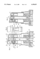
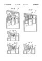
- FIG. 1 is a vertical sectional view of a pump sprayer incorporating one anti-clog feature of the invention with the pump shown in its position of non-use;
- FIG. 2 is a view similar to FIG. 1 showing the discharge orifice uncovered before the plunger pressure stroke;
- FIG. 3 is a partial front elevational view taken substantially along the line 3--3 of FIG. 1;
- FIG. 4 is a view similar to FIG. 1 illustrating another anti-clog feature according to the invention.
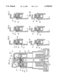
- FIGS. 5, 6, 7, 8, 9 and 10 are views similar to FIG. 1 showing in part the relatively reciprocable cover in the process of uncovering the discharge orifice upon its shifting movement relative to that of the plunger;
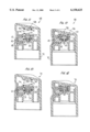
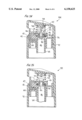
- FIGS. 11 and 12 are views similar to FIG. 1 showing another embodiment of a product retraction device with the cover in its extended and depressed positions;
- FIGS. 13 and 14 are views similar to FIG. 1 of another embodiment of a product retraction device showing the cover in its extended and depressed positions;
- FIGS. 15 and 16 are views similar to FIG. 1 of yet another embodiment of a product retraction device showing the cover in its extended and depressed positions;
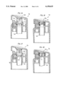
- FIGS. 17 and 18 are views similar to FIG. 1 of yet another embodiment of a product retraction device showing the cover in its extended and depressed positions;
- FIGS. 19 and 20 are view similar to FIG. 1 of still another embodiment of a product retraction device showing the cover in its extended and depressed positions;
- FIGS. 21, 22 and 23 are vertical section views of the plunger head of FIG. 1 of further embodiments of product retraction devices formed by various disc springs;
- FIGS. 24 and 25 are views similar to FIG. 1 of other product retraction devices in the form of elastic diaphragms.
- a precompression pump sprayer 30 is shown in FIG. 1 as having a pump body 31 mountable on the neck of a container (not shown) of liquid product to be dispensed by a provision of a closure 32 to which the pump body is snap-fitted similarly as in prior U.S. Pat. No. 5,785,208.
- the entirety of that patent disclosure is specifically incorporated herein by reference.
- the pump body includes a pump cylinder 40 in which a pump piston 33 reciprocates upon the application of an external force applied as will be described, the piston having a plunger stem 34 on which a plunger head 35 is mounted.
- a discharge poppet valve 36 is shown in FIGS. 1 and 2 seated against its valve seat formed at the confronting lower end of the plunger stem, the poppet being spring biased into its closed position by the provision of a piston return spring (not shown).
- a cover 37 is mounted about the plunger head, the cover being independently reciprocable relative to the plunger against the bias of a spring such as a coil spring 38.
- the cover has an annular side wall 39 containing an opening 41 for exposing discharge orifice 42 formed in a standard orifice cup 43 mounted in the side wall of the plunger head.
- a spin mechanics (not shown) is formed between the end face of probe 45 and the confronting face of the orifice cup.
- An external groove 44 in the probe extends between the spin mechanics arrangement and discharge passage 46 defined by hollow stem 34. Product under pressure therefore flows during pumping via passage 46, through groove 44, is swirled via the spin mechanics, and exits through orifice 42 as a spray upon uncovering the orifice as will be described.
- a portion 47 of side wall 39 seals against the outer face of orifice cup 43 in the non-use position of the pump sprayer shown in FIGS. 1 and 5.
- the inner surface of portion 47 has a circular cup-shaped depression 48 surrounding the orifice in the non-use position of the pump and sealing about the orifice without bearing directly thereagainst.
- Portion 47 is spring biased against the outer face of orifice cup 43 to provide the seal around the orifice, as by the provision of a spring leg 49 formed integrally with side wall 39 formed by a pair of spaced slits 51, as clearly shown FIG. 3.
- cover 37 is capable of being shifted independently of the reciprocation of the plunger from its non-use position of FIG. 1 to its lowered position of FIG. 2 against the bias of its cover spring 38, to thereby expose discharge orifice 42 in readiness for spraying.
- portion 47 of the side wall is lifted off the front face of the orifice cup gradually during cover depression, by the provision of a cam 53 and a cam follower 54 acting between spring leg 49 and the confronting side wall 52 of the plunger head.
- the cam may be in the form of a ramp provided on side wall 52 forming a camming surface
- cam follower 54 may be provided on the inner face of leg 49 which, during downward shifting movement of the cover from its FIG. 1 to its FIG. 2 positions, causes portion 47 of leg 49 to lift off the front face of the orifice cup gradually as shown in sequence in FIGS. 5 to 10.
- the ramp and the cam follower could be otherwise located on the inner face of leg 49 and the outer face of the plunger skirt, respectively, without departing from the invention.
- FIG. 4 Another anti-clog feature of the invention according to one embodiment is illustrated in FIG. 4 in which the manually operated pump sprayer 55 has a product retraction device 56 in open communication with the discharge orifice so that on actuation, a suck-back is created effecting the withdrawal of product inwardly of the orifice to thereby avoid clogging due to dried product in and around the orifice.
- a product retraction device 56 is provided solely on the plunger head 35.
- the underside of top wall 57 of the cover has a probe or a projection 58 extending toward device 56 for actuating the same as will be described.
- the product retraction device of FIG. 4 comprises a cylinder 59 formed integrally at the upper end of the plunger head, and a piston which may be in the form of a disc 61 (which may be metallic) defining together with cylinder 59 a variable volume chamber 62 having a central opening in its bottom wall through which a guide pin 63 of disc 61 extends.
- the pin and/or the central opening has a plurality of spaced grooves or the like to establish communication between chamber 62 and the discharge orifice via groove 44.
- discharge poppet valve 66 is lowered together with the piston, and with the inlet and discharge valves of the pump closed, pressure within pump chamber 67 builds up to a threshold pressure which overcomes the force of the piston return spring. At this threshold pressure poppet valve 66 is forced downwardly away from its valve seat to open the discharge such that product under pressure is dispensed from pump chamber 67 and out through the uncovered discharge orifice via discharge passage 46, groove 44 and the known spin mechanics.
- cover 37 Upon release of the externally applied finger force, cover 37 returns toward its FIG. 4 position under the action of its spring 38 and the piston return stroke commences during which the poppet valve recloses.
- cover 37 Upon return of disc 61 to its FIG.
- cupped portion 47 of the cover seals against the outside of the orifice cup to avoid clogging due to drying.
- any bubble formation or residual product in and around the orifice is simply discharged without dribbling or sputtering.
- Precompression pump sprayer generally designated 68 in FIGS. 11 and 12 has a product retraction device similar to that of FIG. 4 except that piston 61 and its guide pin 63 are of plastic, and its return spring comprises an elastomeric cushion 69 of foamed plastic or the like which is compressible as shown in FIG. 12 upon actuation by projection 58 for actuating device 56.
- Chamber 56 of the FIGS. 13, 14 embodiment is formed by a piston 71 having a plurality of depending spring legs 72 slidable along the outer conical surface of a collar 73 at the bottom end of chamber 62.
- the spring legs function in the same manner as coil spring 62 of FIG. 4 and as spring cushion 69 of FIG. 11, while eliminating the need for a separate spring.
- Pump sprayer 74 of FIGS. 15, 16 has its product retraction device 56 formed by an integral snap diaphragm in the form of a spring washer 75 of concavo-convex shape with its concave side facing toward projection 58.
- Diaphragm 75 defines a miniature chamber 62 therebeneath which after being compressed as shown in FIGS. 16 and expanding back to its position shown in FIG. 15 produces a slight sub-atmospheric pressure to effect withdrawal of product from the discharge orifice as in the manner more fully described in the aforedescribed embodiments.
- Pump sprayer 76 of FIGS. 17, 18 has a product retraction device likewise defined by an integral concavo-convex diaphragm 77 defining a miniature chamber 62 therebeneath.
- the diaphragm functions similarly to that of diaphragm 75 of FIG. 15 except for being mounted in place with a shallower side wall forming chamber 62.
- Pump sprayer 78 of FIGS. 19, 20 has its product retraction device 56 defined by a concavo-convex diaphragm 79 similar to that of diaphragm 76 of FIG. 17 except that diaphragm 79 comprises a separate element mounted in place at the upper end of the plunger head.
- Diaphragm 79 may be of metal or plastic material.
- the product retraction device as shown in FIGS. 21, 22 and 23 each includes a cylinder 59 formed integrally at the upper end of the plunger head, and each includes a piston in the form of a disc 61 having a central guide pin 63, similar to that of FIG. 4.
- Each disc 61 is actuated by projection 58 against the bias of a disc spring.
- a spring washer 81 is provided for spring biasing piston disc 61.
- a Belleville spring 82 is provided to facilitate spring return of piston disc 61 upon impact by projection 58
- a flat spring 83 is provided for this purpose.
- the pump sprayer generally designated 84 in FIG. 24 has an upstanding collar 85 formed at the upper end of the plunger head 35 on which diaphragm 86 is mounted.
- the diaphragm is of elastomeric material capable of stretching, such as a soft polyethylene, Santoprene, rubber and the like.
- the diaphragm has spaced inner and outer annular walls 87, 88 located upon assembly on opposite sides of collar 85, inner wall having a closed bottom 89 presenting with the inner wall a central depression 91.
- cover 37 shifts downwardly relative to plunger head 35 upon the application of external finger force against top wall 37 of the cover.
- spring biased portion 47 of the cover lifts away from the discharge orifice as shown in sequence in FIGS. 5 to 10.
- projection 58 extends into depression 91 and by the time the underside of top wall 57 contacts upper edge 65 of the plunger head the projection will have stretched inner wall 87 of the diaphragm thereby effectively compressing the fluid in passage 46 to a small extent.
- Continued pressure applied against the cover is transmitted to the plunger which lowers the pump piston in its cylinder to thereby pressurize the liquid product contained in the pump chamber which builds up to a threshold pressure.
- the pump sprayer generally designated 92 in FIG. 25 has its product retraction device 56 comprising an elastomeric diaphragm 93 which is likewise of a stretchy polyethylene, Santoprene, rubber or some other type of elastomer, which is essentially hat-shaped as shown.
- the annular crown portion of the hat-shaped diaphragm is fitted about collar 85, and the transverse flange 94 provides a support for cover return spring 38 as shown.
- a simple and economical yet highly effective pump sprayer with one or more anti-clog features has been devised in which a product retraction device is provided solely on the plunger head and is actuated by an independently shiftable cover which engages the product retraction device at the commencement of the plunger pressure stroke, and disengages the product retraction device at the beginning of the plunger return stroke for suctioning any residual product from in and around the discharge orifice to thereby avoid clogging and to prevent the formation of air bubbles upstream of the orifice.
- the product retraction device slightly increases the volume of the discharge passage which is in communication with the discharge orifice to thereby retract product from the discharge orifice without the formation of any air bubbles forming behind the orifice cup. Since the product retraction device is mounted solely on the plunger head, any leakage between such device and the cover is avoided, and a wide variety of styles of product retraction devices is made possible compared to that available for the prior art. Moreover, the product retraction device according to the invention does not rely on a peak pressure which accumulates in the pump chamber which must exceed the design force of a spring to effect the relative shift between the cover and the plunger head, as set forth in the prior art.
- Another anti-clog feature of the invention which may be employed independently of or together with the aforementioned anti-clog feature, has a spring biased cupped portion on the cover which seals the discharge orifice closed upon a return movement of the cover, and which gradually without contacting the orifice is lifted off the orifice cup upon cover movement toward the plunger.
Landscapes
- Reciprocating Pumps (AREA)
Abstract
Description
Claims (18)
Priority Applications (2)
| Application Number | Priority Date | Filing Date | Title |
|---|---|---|---|
| US09/375,432 US6158625A (en) | 1999-08-17 | 1999-08-17 | Anti-clog pump sprayer |
| US09/649,016 US6223951B1 (en) | 1999-08-17 | 2000-08-28 | Anti-clog pump sprayer |
Applications Claiming Priority (1)
| Application Number | Priority Date | Filing Date | Title |
|---|---|---|---|
| US09/375,432 US6158625A (en) | 1999-08-17 | 1999-08-17 | Anti-clog pump sprayer |
Related Child Applications (1)
| Application Number | Title | Priority Date | Filing Date |
|---|---|---|---|
| US09/649,016 Division US6223951B1 (en) | 1999-08-17 | 2000-08-28 | Anti-clog pump sprayer |
Publications (1)
| Publication Number | Publication Date |
|---|---|
| US6158625A true US6158625A (en) | 2000-12-12 |
Family
ID=23480872
Family Applications (2)
| Application Number | Title | Priority Date | Filing Date |
|---|---|---|---|
| US09/375,432 Expired - Lifetime US6158625A (en) | 1999-08-17 | 1999-08-17 | Anti-clog pump sprayer |
| US09/649,016 Expired - Lifetime US6223951B1 (en) | 1999-08-17 | 2000-08-28 | Anti-clog pump sprayer |
Family Applications After (1)
| Application Number | Title | Priority Date | Filing Date |
|---|---|---|---|
| US09/649,016 Expired - Lifetime US6223951B1 (en) | 1999-08-17 | 2000-08-28 | Anti-clog pump sprayer |
Country Status (1)
| Country | Link |
|---|---|
| US (2) | US6158625A (en) |
Cited By (24)
| Publication number | Priority date | Publication date | Assignee | Title |
|---|---|---|---|---|
| US6257451B1 (en) * | 2000-06-01 | 2001-07-10 | Saint-Gobain Calmar Inc. | Anti-clog pump sprayer |
| WO2003004374A1 (en) * | 2001-06-29 | 2003-01-16 | Wilden Ag | Dispenser for pasty products |
| US20030160113A1 (en) * | 2002-02-28 | 2003-08-28 | Dobbs Douglas B. | Orifice cup for manually actuated sprayer |
| US20050133542A1 (en) * | 2003-12-17 | 2005-06-23 | Deutsche Prazisions-Ventil Gmbh | Aerosol valve actuator |
| US20070194049A1 (en) * | 2006-02-22 | 2007-08-23 | Schmitt William H | Clog resistant actuator and overcap |
| US20080138143A1 (en) * | 2006-12-12 | 2008-06-12 | O'connell Tami | Fluid Dispensing Systems For Pump Dispenser for Use With Substrates |
| US20080166174A1 (en) * | 2007-01-09 | 2008-07-10 | Timothy James Kennedy | Fluid Dispensing System with Separate Pump Actuator and Dispensing Pad |
| US20080202556A1 (en) * | 2006-10-23 | 2008-08-28 | Pivonka Nicholas L | One-Handed Method of Cleaning Surfaces |
| US20080273915A1 (en) * | 2007-05-01 | 2008-11-06 | O'connell Tami | Sensory Cue For Pump Dispenser For Use With Substrates |
| US20080314925A1 (en) * | 2007-06-25 | 2008-12-25 | Timothy Kennedy | Gravity-Flow Liquid Drain-Back System for a Dispensing Package |
| US20090001099A1 (en) * | 2007-06-27 | 2009-01-01 | Timothy Kennedy | Liquid Draw-Back System for a Dispensing Package |
| US20090014474A1 (en) * | 2007-07-02 | 2009-01-15 | Timothy Kennedy | Through-Pump Liquid Drain-Back System for a Dispensing Package |
| US20090101676A1 (en) * | 2007-10-22 | 2009-04-23 | O'connell Tami | Pump Dispenser With Indented Actuator Skirt |
| US7871217B2 (en) | 2006-12-12 | 2011-01-18 | The Clorox Company | Pump systems for pump dispensers |
| US20110031275A1 (en) * | 2009-08-07 | 2011-02-10 | Ecolab Usa Inc. | Wipe and seal product pump |
| WO2011060831A1 (en) * | 2009-11-20 | 2011-05-26 | Kaehler Pia | Spraying device with automatically actuated shutter |
| WO2012126920A1 (en) * | 2011-03-23 | 2012-09-27 | Rpc Bramlage Gmbh | Dispenser |
| US20130119088A1 (en) * | 2010-08-03 | 2013-05-16 | Toyo Aerosol Industry Co., Ltd. | Actuator For An Aerosol Container |
| USD717666S1 (en) | 2014-03-14 | 2014-11-18 | The Clorox Company | Fluid dispenser |
| EP3261781A4 (en) * | 2015-02-27 | 2018-05-30 | AptarGroup, Inc. | Actuating system for a fluent substance dispensing system |
| US9986809B2 (en) | 2013-06-28 | 2018-06-05 | The Procter & Gamble Company | Aerosol hairspray product comprising a spraying device |
| US10131488B2 (en) | 2015-06-01 | 2018-11-20 | The Procter And Gamble Company | Aerosol hairspray product comprising a spraying device |
| US10426979B2 (en) | 2011-09-15 | 2019-10-01 | The Procter And Gamble Company | Aerosol hairspray product for styling and/or shaping hair |
| USD980069S1 (en) | 2020-07-14 | 2023-03-07 | Ball Corporation | Metallic dispensing lid |
Families Citing this family (8)
| Publication number | Priority date | Publication date | Assignee | Title |
|---|---|---|---|---|
| FR2796921B1 (en) * | 1999-07-28 | 2001-10-05 | Valois Sa | FLUID PRODUCT DISPENSING DEVICE WITH SHUTTERING SYSTEM |
| ES2337882T3 (en) * | 2001-05-14 | 2010-04-30 | M-Heat Investors, Llc | SYSTEM AND METHOD FOR CLEANING OR DEFROSTING A WINDSHIELD. |
| MXPA05004213A (en) * | 2002-10-21 | 2005-11-17 | Microheat Inc | Apparatus and method for cleaning or de-icing vehicle elements. |
| DE602004028962D1 (en) * | 2003-12-22 | 2010-10-14 | Valois Sas | LIQUID DISPENSER UNIT AND CONTAINER WITH SUCH A UNIT |
| WO2005076735A2 (en) * | 2004-02-12 | 2005-08-25 | Microheat Inc. | Apparatus and method for cleaning and de-icing |
| KR20090035002A (en) | 2006-07-24 | 2009-04-08 | 마이크로 히트 인코퍼레이티드 | Vehicle surfaces cleaning and de-icing system and method |
| US11267009B1 (en) * | 2021-01-25 | 2022-03-08 | The Procter & Gamble Company | Manually operated dispensing pump |
| US11338310B1 (en) * | 2021-01-25 | 2022-05-24 | The Procter & Gamble Company | Manually operated dispensing pump |
Citations (4)
| Publication number | Priority date | Publication date | Assignee | Title |
|---|---|---|---|---|
| US5094364A (en) * | 1990-06-15 | 1992-03-10 | Calmar Inc. | Protective overcap and wiper for dispenser discharge orifice |
| US5105988A (en) * | 1990-06-15 | 1992-04-21 | Calmar Inc. | Protector cap and wiper for dispenser discharge orifice |
| US5207785A (en) * | 1991-08-19 | 1993-05-04 | Calmar Inc. | Protector cap and wiper for dispenser discharge orifice |
| US5785208A (en) * | 1996-04-10 | 1998-07-28 | Calmar Inc. | Precompression pump sprayer having suck-back feature |
Family Cites Families (7)
| Publication number | Priority date | Publication date | Assignee | Title |
|---|---|---|---|---|
| US3779464A (en) * | 1972-03-22 | 1973-12-18 | Afa Corp | Manually actuated liquid spraying device |
| CA1008825A (en) * | 1974-03-28 | 1977-04-19 | William E. Warren | Pump assembly for an atomizing piston pump |
| US4051983B1 (en) * | 1975-11-19 | 1993-12-14 | Calmar Inc. | Pump sprayer having pump priming means |
| US4516727A (en) * | 1983-05-26 | 1985-05-14 | Yoshino Kogyosho Co., Ltd. | Manually-operated sprayer |
| ES2011140A6 (en) * | 1988-10-10 | 1989-12-16 | Monturas Sa | A spray pump. |
| US5348189A (en) * | 1991-04-10 | 1994-09-20 | Bespak Plc | Air purge pump dispenser |
| US5358149A (en) * | 1992-12-17 | 1994-10-25 | Neill Richard K O | Pressure build-up pump sprayer having anti-clogging means |
-
1999
- 1999-08-17 US US09/375,432 patent/US6158625A/en not_active Expired - Lifetime
-
2000
- 2000-08-28 US US09/649,016 patent/US6223951B1/en not_active Expired - Lifetime
Patent Citations (4)
| Publication number | Priority date | Publication date | Assignee | Title |
|---|---|---|---|---|
| US5094364A (en) * | 1990-06-15 | 1992-03-10 | Calmar Inc. | Protective overcap and wiper for dispenser discharge orifice |
| US5105988A (en) * | 1990-06-15 | 1992-04-21 | Calmar Inc. | Protector cap and wiper for dispenser discharge orifice |
| US5207785A (en) * | 1991-08-19 | 1993-05-04 | Calmar Inc. | Protector cap and wiper for dispenser discharge orifice |
| US5785208A (en) * | 1996-04-10 | 1998-07-28 | Calmar Inc. | Precompression pump sprayer having suck-back feature |
Cited By (47)
| Publication number | Priority date | Publication date | Assignee | Title |
|---|---|---|---|---|
| US6257451B1 (en) * | 2000-06-01 | 2001-07-10 | Saint-Gobain Calmar Inc. | Anti-clog pump sprayer |
| US6955278B2 (en) | 2001-06-29 | 2005-10-18 | Wilden Ag | Dispenser for paste-like products |
| WO2003004374A1 (en) * | 2001-06-29 | 2003-01-16 | Wilden Ag | Dispenser for pasty products |
| US20040206781A1 (en) * | 2001-06-29 | 2004-10-21 | Willy Lorscheidt | Dispenser for paste-like products |
| US20030160113A1 (en) * | 2002-02-28 | 2003-08-28 | Dobbs Douglas B. | Orifice cup for manually actuated sprayer |
| US6793156B2 (en) * | 2002-02-28 | 2004-09-21 | Saint-Gobain Calmar Inc. | Orifice cup for manually actuated sprayer |
| AU2003200669B2 (en) * | 2002-02-28 | 2005-04-28 | Saint-Gobain Calmar Inc. | Orifice cup for manually actuated sprayer |
| US20050133542A1 (en) * | 2003-12-17 | 2005-06-23 | Deutsche Prazisions-Ventil Gmbh | Aerosol valve actuator |
| US20060151547A1 (en) * | 2003-12-17 | 2006-07-13 | Gunter Kolanus | Aerosol valve actuator |
| EP1694566A2 (en) * | 2003-12-17 | 2006-08-30 | Precision Valve Corporation | Aerosol valve actuator |
| US7104424B2 (en) | 2003-12-17 | 2006-09-12 | Precision Valve Corporation | Aerosol valve actuator |
| US7582242B2 (en) | 2003-12-17 | 2009-09-01 | Precision Valve Corporation | Method of forming an aerosol valve actuator |
| EP1694566A4 (en) * | 2003-12-17 | 2008-09-10 | Precision Valve Corp | Aerosol valve actuator |
| EP2298655A1 (en) * | 2003-12-17 | 2011-03-23 | Precision Valve Corporation | Aerosol valve actuator |
| US7510102B2 (en) * | 2006-02-22 | 2009-03-31 | Schmitt William H | Clog resistant actuator and overcap |
| US20070194049A1 (en) * | 2006-02-22 | 2007-08-23 | Schmitt William H | Clog resistant actuator and overcap |
| US20080202556A1 (en) * | 2006-10-23 | 2008-08-28 | Pivonka Nicholas L | One-Handed Method of Cleaning Surfaces |
| US7984832B2 (en) | 2006-10-23 | 2011-07-26 | The Clorox Company | Pump dispenser for use with substrates |
| US7871217B2 (en) | 2006-12-12 | 2011-01-18 | The Clorox Company | Pump systems for pump dispensers |
| US20080245821A1 (en) * | 2006-12-12 | 2008-10-09 | Laura Itzkowitz | Pump Dispenser for Use with Thickened Liquids and Substrates |
| US20080138143A1 (en) * | 2006-12-12 | 2008-06-12 | O'connell Tami | Fluid Dispensing Systems For Pump Dispenser for Use With Substrates |
| US7980777B2 (en) | 2007-01-09 | 2011-07-19 | The Clorox Company | Fluid dispensing system with separate pump actuator and dispensing pad |
| US20080166174A1 (en) * | 2007-01-09 | 2008-07-10 | Timothy James Kennedy | Fluid Dispensing System with Separate Pump Actuator and Dispensing Pad |
| US20080273915A1 (en) * | 2007-05-01 | 2008-11-06 | O'connell Tami | Sensory Cue For Pump Dispenser For Use With Substrates |
| US20080314925A1 (en) * | 2007-06-25 | 2008-12-25 | Timothy Kennedy | Gravity-Flow Liquid Drain-Back System for a Dispensing Package |
| US7726517B2 (en) | 2007-06-27 | 2010-06-01 | The Clorox Company | Liquid draw-back system for a dispensing package |
| US20090001099A1 (en) * | 2007-06-27 | 2009-01-01 | Timothy Kennedy | Liquid Draw-Back System for a Dispensing Package |
| US7712633B2 (en) | 2007-07-02 | 2010-05-11 | The Clorox Company | Through-pump liquid drain-back system for a dispensing package |
| US20090014474A1 (en) * | 2007-07-02 | 2009-01-15 | Timothy Kennedy | Through-Pump Liquid Drain-Back System for a Dispensing Package |
| US20090101676A1 (en) * | 2007-10-22 | 2009-04-23 | O'connell Tami | Pump Dispenser With Indented Actuator Skirt |
| WO2011016011A2 (en) * | 2009-08-07 | 2011-02-10 | Ecolab Usa Inc. | Wipe and seal product pump |
| US20110031275A1 (en) * | 2009-08-07 | 2011-02-10 | Ecolab Usa Inc. | Wipe and seal product pump |
| WO2011016011A3 (en) * | 2009-08-07 | 2011-08-25 | Ecolab Usa Inc. | Wipe and seal product pump |
| US8444019B2 (en) * | 2009-08-07 | 2013-05-21 | Ecolab Usa Inc. | Wipe and seal product pump |
| WO2011060831A1 (en) * | 2009-11-20 | 2011-05-26 | Kaehler Pia | Spraying device with automatically actuated shutter |
| CN102639251B (en) * | 2009-11-20 | 2015-11-25 | 皮亚·凯勒 | There is the sprayer unit of the cover plate be automatically driven |
| US8925765B2 (en) * | 2010-08-03 | 2015-01-06 | Toyo Aerosol Industry Co., Ltd. | Actuator for an aerosol container |
| US20130119088A1 (en) * | 2010-08-03 | 2013-05-16 | Toyo Aerosol Industry Co., Ltd. | Actuator For An Aerosol Container |
| WO2012126920A1 (en) * | 2011-03-23 | 2012-09-27 | Rpc Bramlage Gmbh | Dispenser |
| US9205439B2 (en) | 2011-03-23 | 2015-12-08 | Rpc Bramlage Gmbh | Dispenser |
| US10426979B2 (en) | 2011-09-15 | 2019-10-01 | The Procter And Gamble Company | Aerosol hairspray product for styling and/or shaping hair |
| US11311749B2 (en) | 2011-09-15 | 2022-04-26 | The Procter And Gamble Company | Aerosol hairspray for styling and/or shaping hair |
| US9986809B2 (en) | 2013-06-28 | 2018-06-05 | The Procter & Gamble Company | Aerosol hairspray product comprising a spraying device |
| USD717666S1 (en) | 2014-03-14 | 2014-11-18 | The Clorox Company | Fluid dispenser |
| EP3261781A4 (en) * | 2015-02-27 | 2018-05-30 | AptarGroup, Inc. | Actuating system for a fluent substance dispensing system |
| US10131488B2 (en) | 2015-06-01 | 2018-11-20 | The Procter And Gamble Company | Aerosol hairspray product comprising a spraying device |
| USD980069S1 (en) | 2020-07-14 | 2023-03-07 | Ball Corporation | Metallic dispensing lid |
Also Published As
| Publication number | Publication date |
|---|---|
| US6223951B1 (en) | 2001-05-01 |
Similar Documents
| Publication | Publication Date | Title |
|---|---|---|
| US6158625A (en) | Anti-clog pump sprayer | |
| JP3372166B2 (en) | Pre-compression pump type spray | |
| US5785208A (en) | Precompression pump sprayer having suck-back feature | |
| US4144987A (en) | Liquid sprayer | |
| JPS6028529Y2 (en) | Pressure accumulating type sprayer | |
| US4371097A (en) | Liquid dispensing pump | |
| US4591077A (en) | Continuous discharge dispenser | |
| US5181635A (en) | Liquid pump dispenser having a stationary spout | |
| US4596344A (en) | Manually actuated dispenser | |
| US6257451B1 (en) | Anti-clog pump sprayer | |
| US4494680A (en) | Manually operated dispensing pump | |
| US5242089A (en) | Miniature pump sprayer | |
| US6371337B2 (en) | Dispensing member having an outlet valve formed by a differential piston | |
| KR20010105164A (en) | Double spring precompression pump with priming feature | |
| US4643338A (en) | Manual liquid dispenser | |
| US5425477A (en) | Pump sprayer with stationary discharge | |
| US5284276A (en) | Pump dispenser with combined inlet and outlet ports | |
| JP3193264B2 (en) | Pump sprayer | |
| US20190091710A1 (en) | Dispenser pumps | |
| JP2816179B2 (en) | Finger operated pump | |
| RU2002516C1 (en) | Manual sprayer of fluid |
Legal Events
| Date | Code | Title | Description |
|---|---|---|---|
| AS | Assignment |
Owner name: CALMAR INC., CALIFORNIA Free format text: ASSIGNMENT OF ASSIGNORS INTEREST;ASSIGNORS:SIEGEL, KENNETH D.;LI, TANNY;REEL/FRAME:010189/0846 Effective date: 19990810 |
|
| STCF | Information on status: patent grant |
Free format text: PATENTED CASE |
|
| FPAY | Fee payment |
Year of fee payment: 4 |
|
| FEPP | Fee payment procedure |
Free format text: PAYOR NUMBER ASSIGNED (ORIGINAL EVENT CODE: ASPN); ENTITY STATUS OF PATENT OWNER: LARGE ENTITY Free format text: PAYER NUMBER DE-ASSIGNED (ORIGINAL EVENT CODE: RMPN); ENTITY STATUS OF PATENT OWNER: LARGE ENTITY |
|
| FPAY | Fee payment |
Year of fee payment: 8 |
|
| AS | Assignment |
Owner name: MEADWESTVACO CALMAR, INC., MISSOURI Free format text: CHANGE OF NAME;ASSIGNORS:CALMAR INC.;SAINT-GOBAIN CALMAR INC.;REEL/FRAME:021339/0690;SIGNING DATES FROM 20001110 TO 20060705 |
|
| AS | Assignment |
Owner name: MEADWESTVACO CALMAR, INC., MISSOURI Free format text: CHANGE OF NAME;ASSIGNOR:SAINT-GOBAIN CALMAR INC.;REEL/FRAME:021354/0381 Effective date: 20060705 Owner name: SAINT-GOBAIN CALMAR INC., CALIFORNIA Free format text: CORRECTIVE ASSIGNMENT TO CORRECT THE ASSIGNOR NAME PREVIOUSLY RECORDED ON REEL 021339 FRAME 0690. ASSIGNOR(S) HEREBY CONFIRMS THE CHANGE OF NAME.;ASSIGNOR:CALMAR INC.;REEL/FRAME:021354/0374 Effective date: 20001110 |
|
| FPAY | Fee payment |
Year of fee payment: 12 |
|
| AS | Assignment |
Owner name: WESTROCK DISPENSING SYSTEMS, INC., GEORGIA Free format text: CHANGE OF NAME;ASSIGNOR:MEADWESTVACO CALMAR, INC.;REEL/FRAME:040652/0288 Effective date: 20150818 |
|
| AS | Assignment |
Owner name: SILGAN DISPENSING SYSTEMS CORPORATION, MISSOURI Free format text: CHANGE OF NAME;ASSIGNOR:WESTROCK DISPENSING SYSTEMS, INC.;REEL/FRAME:050160/0237 Effective date: 20170505 |