EP0616843A2 - System zum kontinuierlichen Überwachen des Aushärtungsenergiepegels innerhalb einer Aushärtungsvorrichtung - Google Patents
System zum kontinuierlichen Überwachen des Aushärtungsenergiepegels innerhalb einer Aushärtungsvorrichtung Download PDFInfo
- Publication number
- EP0616843A2 EP0616843A2 EP94301497A EP94301497A EP0616843A2 EP 0616843 A2 EP0616843 A2 EP 0616843A2 EP 94301497 A EP94301497 A EP 94301497A EP 94301497 A EP94301497 A EP 94301497A EP 0616843 A2 EP0616843 A2 EP 0616843A2
- Authority
- EP
- European Patent Office
- Prior art keywords
- curing
- coating material
- radiation
- reflector
- available
- Prior art date
- Legal status (The legal status is an assumption and is not a legal conclusion. Google has not performed a legal analysis and makes no representation as to the accuracy of the status listed.)
- Ceased
Links
Images


Classifications
-
- B—PERFORMING OPERATIONS; TRANSPORTING
- B29—WORKING OF PLASTICS; WORKING OF SUBSTANCES IN A PLASTIC STATE IN GENERAL
- B29C—SHAPING OR JOINING OF PLASTICS; SHAPING OF MATERIAL IN A PLASTIC STATE, NOT OTHERWISE PROVIDED FOR; AFTER-TREATMENT OF THE SHAPED PRODUCTS, e.g. REPAIRING
- B29C35/00—Heating, cooling or curing, e.g. crosslinking or vulcanising; Apparatus therefor
- B29C35/02—Heating or curing, e.g. crosslinking or vulcanizing during moulding, e.g. in a mould
- B29C35/0288—Controlling heating or curing of polymers during moulding, e.g. by measuring temperatures or properties of the polymer and regulating the process
-
- B—PERFORMING OPERATIONS; TRANSPORTING
- B01—PHYSICAL OR CHEMICAL PROCESSES OR APPARATUS IN GENERAL
- B01J—CHEMICAL OR PHYSICAL PROCESSES, e.g. CATALYSIS OR COLLOID CHEMISTRY; THEIR RELEVANT APPARATUS
- B01J19/00—Chemical, physical or physico-chemical processes in general; Their relevant apparatus
- B01J19/08—Processes employing the direct application of electric or wave energy, or particle radiation; Apparatus therefor
- B01J19/12—Processes employing the direct application of electric or wave energy, or particle radiation; Apparatus therefor employing electromagnetic waves
- B01J19/122—Incoherent waves
- B01J19/123—Ultraviolet light
-
- B—PERFORMING OPERATIONS; TRANSPORTING
- B05—SPRAYING OR ATOMISING IN GENERAL; APPLYING FLUENT MATERIALS TO SURFACES, IN GENERAL
- B05D—PROCESSES FOR APPLYING FLUENT MATERIALS TO SURFACES, IN GENERAL
- B05D3/00—Pretreatment of surfaces to which liquids or other fluent materials are to be applied; After-treatment of applied coatings, e.g. intermediate treating of an applied coating preparatory to subsequent applications of liquids or other fluent materials
- B05D3/06—Pretreatment of surfaces to which liquids or other fluent materials are to be applied; After-treatment of applied coatings, e.g. intermediate treating of an applied coating preparatory to subsequent applications of liquids or other fluent materials by exposure to radiation
- B05D3/061—Pretreatment of surfaces to which liquids or other fluent materials are to be applied; After-treatment of applied coatings, e.g. intermediate treating of an applied coating preparatory to subsequent applications of liquids or other fluent materials by exposure to radiation using U.V.
- B05D3/065—After-treatment
- B05D3/067—Curing or cross-linking the coating
-
- B—PERFORMING OPERATIONS; TRANSPORTING
- B29—WORKING OF PLASTICS; WORKING OF SUBSTANCES IN A PLASTIC STATE IN GENERAL
- B29C—SHAPING OR JOINING OF PLASTICS; SHAPING OF MATERIAL IN A PLASTIC STATE, NOT OTHERWISE PROVIDED FOR; AFTER-TREATMENT OF THE SHAPED PRODUCTS, e.g. REPAIRING
- B29C35/00—Heating, cooling or curing, e.g. crosslinking or vulcanising; Apparatus therefor
- B29C35/02—Heating or curing, e.g. crosslinking or vulcanizing during moulding, e.g. in a mould
- B29C35/08—Heating or curing, e.g. crosslinking or vulcanizing during moulding, e.g. in a mould by wave energy or particle radiation
- B29C35/10—Heating or curing, e.g. crosslinking or vulcanizing during moulding, e.g. in a mould by wave energy or particle radiation for articles of indefinite length
-
- C—CHEMISTRY; METALLURGY
- C03—GLASS; MINERAL OR SLAG WOOL
- C03C—CHEMICAL COMPOSITION OF GLASSES, GLAZES OR VITREOUS ENAMELS; SURFACE TREATMENT OF GLASS; SURFACE TREATMENT OF FIBRES OR FILAMENTS MADE FROM GLASS, MINERALS OR SLAGS; JOINING GLASS TO GLASS OR OTHER MATERIALS
- C03C25/00—Surface treatment of fibres or filaments made from glass, minerals or slags
- C03C25/10—Coating
- C03C25/12—General methods of coating; Devices therefor
-
- B—PERFORMING OPERATIONS; TRANSPORTING
- B29—WORKING OF PLASTICS; WORKING OF SUBSTANCES IN A PLASTIC STATE IN GENERAL
- B29C—SHAPING OR JOINING OF PLASTICS; SHAPING OF MATERIAL IN A PLASTIC STATE, NOT OTHERWISE PROVIDED FOR; AFTER-TREATMENT OF THE SHAPED PRODUCTS, e.g. REPAIRING
- B29C35/00—Heating, cooling or curing, e.g. crosslinking or vulcanising; Apparatus therefor
- B29C35/02—Heating or curing, e.g. crosslinking or vulcanizing during moulding, e.g. in a mould
- B29C35/08—Heating or curing, e.g. crosslinking or vulcanizing during moulding, e.g. in a mould by wave energy or particle radiation
- B29C35/0805—Heating or curing, e.g. crosslinking or vulcanizing during moulding, e.g. in a mould by wave energy or particle radiation using electromagnetic radiation
- B29C2035/0827—Heating or curing, e.g. crosslinking or vulcanizing during moulding, e.g. in a mould by wave energy or particle radiation using electromagnetic radiation using UV radiation
Definitions
- This invention relates to a system for continuously monitoring curing energy levels within a curing unit.
- Radiation curable materials have penetrated several areas of commerce due to their characteristic rapid processing speeds.
- One class of radiation curable materials are converted from a liquid to a solid upon exposure to ultraviolet portion of the electromagnetic spectrum. Such materials are commonly referred to as UV curable materials. Examples of such materials include UV curable optical fiber coatings, optical fiber cabling materials, adhesives, floor coatings, wood coatings, and metal beverage can coatings.
- Another class of radiation curable materials are converted from a liquid to a solid upon exposure to visible light. Such materials are commonly referred to as visible light curable materials. Examples of such materials include optical fiber coatings, pigmented inks, and adhesives.
- Cure dose is a variable which is sought to be carefully controlled during processing of radiation curable materials in order to ensure complete cure of the material.
- a preform is suspended vertically and moved into a furnace.
- Optical fiber is drawn from the preform and afterwards is provided with one or more layers of various liquid coating material.
- the liquid coating material is a curable coating material and typically it is an ultraviolet (UV) light energy curable material.
- Curing of the coating materials is accomplished by moving successive lengths of the optical fiber having the coating material thereon through a center tube which is disposed within an elliptically shaped housing as depicted in U.S. Patent 5,000,772. At one loci of the elliptical shape is disposed a curing lamp; at the other, the center tube.
- the elliptical housing has reflective surfaces for reflecting curing energy toward engagement with the optical fiber.
- a quartz center tube is sometimes used to maintain an oxygen-free atmosphere (N2) for a high degree of cure of the secondary or exterior coating layer.
- the interior surface of the center tube is often adiabatic.
- the heat of polymerization of the coating material and the absorption of radiation from the UV lamps may heat the fiber temperature to about 130°C or higher.
- coating materials devolitize at temperatures greater than about 90°C, deposits of volatiles form on the inner surface of the center tube even during normal usage.
- FIG. 1 there is shown an apparatus which is designated generally by the numeral 20 and in which is used to draw optical fiber 21 from a specially prepared cylindrical preform 22 and for then coating the fiber.
- the optical fiber 21 is formed by locally and symmetrically heating the preform 22, typically 7 to 25 mm in diameter and 60 cm in length, to a temperature of about 2000 ° C. As the preform is fed into and through a furnace 23, fiber 21 is drawn from the molten material.
- the elements of the draw system include the furnace 23 wherein the preform is drawn down to the fiber size after which the fiber 21 is pulled from the heat zone.
- the diameter of the fiber 21 is measured by a device 24 at a point shortly after the fiber is formed and this measured value becomes an input into a control system.
- the measured diameter is compared to the desired value and an output signal is generated to adjust the draw speed such that the fiber diameter approaches the desired value.
- a protective coating 25 (see also FIG. 2) is applied to it by apparatus 27.
- Preservation of fiber strength requires the application of the protective coating, which shields newly drawn fiber from the deleterious effects of the atmosphere.
- This coating must be applied in a manner that does not damage the surface of the fiber 21 and such that the fiber has a predetermined diameter and is protected from abrasion during subsequent manufacturing operations, installation and service. Minimizing attenuation requires the selection of a suitable coating material and a controlled application of it to the fiber.
- Such a coating apparatus may be one such as that described in U.S. Patent 4,474,830.
- the coating material After the coating material has been applied to the drawn fiber, the coating material must be cured. Accordingly, the optical fiber having the coating material thereon is passed through a device 30 for curing the coating and a device 32 for measuring the outer diameter of the coated fiber. Afterwards, it is moved through a capstan 34 and is spooled for testing and storage prior to subsequent cable operations.
- bonded ribbons include a plurality of coated optical fibers disposed in a planar array and held together in that array by a matrix material.
- coating material or to the matrix material, it should be understood that the following applies to both.
- the line 40 is capable of manufacturing a bonded ribbon 42 (see FIG. 4).
- the ribbon 42 includes a plurality of coated optical fibers 36-36 each of which includes a core, a cladding and one or more layers 2525 of coating material.
- the optical fibers 36-36 may be disposed in a planar array.
- the fibers are held bonded together in that array by a matrix material 45.
- the matrix material is an ultraviolet (UV) curable material.
- a plurality of the optical fibers 36-36 are payed out from supplies 46-46, and an ink from a reservoir is applied thereto by an applicator 48. Afterwards, the ink is dried in an oven 49. Then the optical fibers are gathered together and embedded in the curable matrix material in an applicator 52.
- the applicator 52 may be an extruder, for example. Afterwards, the array in the matrix material is directed past an apparatus 54 which is well known and which is used to cure the curable matrix material and taken up on a spool 56.
- the coating or the matrix material must be cured.
- the coating material may be cured by thermal, electron beam, microwave, or ultraviolet energy.
- the curable material may comprise a silicone-based material, an acrylate-based material or a vinyl-based material.
- radiation-curable coatings for optical glass fiber may be of various types, but it is always necessary to provide the low to moderate tensile modulus needed in a coating which will contact the glass, to employ a polyethylenic polymeric organic compound. Many appropriate polyethylenic organic compounds are known and are deemed acceptable and within the scope of the present invention.
- the present invention is directed to a method and apparatus for monitoring the overall operational effectiveness of a curing system specifically addressing such systems presently used in drawing optical fiber.
- factors include 1) the output power output level of the radiation source, 2) the cleanliness of the center tube if such device is used, and 3) the efficiency of the reflector system.
- the present invention is capable of continuously gauging substantial changes in any of the three factors identified above which may adversely affect the ultimate cure of the coatings.
- the optical fiber coatings emit chemical vapors during the drawing of optical fiber from a preform. These vapors deposit on an inner surface of the center tube and significantly attenuate UV light energy which reaches the optical fiber coating during a draw. A possible consequence of excessive attenuation of UV curing light energy is an unacceptable degree of cure of the coating materials.
- the curing apparatus of the present invention includes an elliptically shaped reflector 60 comprising a primary reflector portion 62 and a back reflector 64.
- a radiation curing source 66 which is preferably an ultraviolet light energy bulb, is disposed at one of the loci of the elliptical geometry. Successive increments of length of the drawn optical fibers are moved through a center tube 68.
- the center tube 68 is made of quartz and is disposed at the other loci of the elliptical shape.
- a center tube monitor may be positioned directly behind the quartz center tube 68 away from the UV light source 66. Additionally, a center tube sensor 70 measures the amount of curing radiation which is transmitted through the center tube 68 to impinge on the optical fiber coating material 25. In addition, a reference monitor may be positioned beyond the quartz center tube 68 and is used to measure the amount of light emitted directly from the UV bulb 66.
- other calibration techniques may be employed to periodically generate an average radiometry reading along the length of the fiber, thereby alleviating the need to continuously monitor the radiation output of the source.
- One such alternative calibration method may involve establishing an emission value for a new radiation source and, based on a profile of the projected life deterioration of such sources, generating an ongoing and accurate base or reference output value of that radiation source throughout its life .
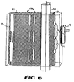
- one embodiment of the present invention introduces one hole 72 into the housing of curing assembly and three additional longitudinally arranged holes 74-74 through the reflector surface on the center tube side. Once the radiation is transmitted through the center tube 68, these holes 74-74 provide a path for radiation to pass from the bulb 66 through the reflector surface 64 to the sensor 70.
- the light path described above is indirect since the reflector holes 74-74 are purposefully not aligned with the radiation sensor hole 72.
- the plurality of misaligned holes 74-74 establishes the monitor reading as an accurate representation of the average clouding of the center tube, unbiased by an isolated high-intensity signal passing through a single section of the center tube. Additionally, the particular hole alignment of the present invention reduces the effects of alignment error that often occurs during installation of center tube 68.
- the present invention may be directed at serving and measuring various forms of radiation, it should be noted that any well known type of radiometry may be used in accordance with the present invention.
- the radiation sensor 70 includes a plurality of photodiodes with a sensitivity value in the range of 320-390 nm and are mounted in a heat-insulating phenolic block 76.
- a heat-insulating phenolic block 76 Such devices are presently available from Electronic Instrumentation and Technologies Corp. of Sterling, Virginia.
- the block 76 should be thick enough to act as a sufficient thermal insulator for the cured dose monitoring system. In general, the mounting block 76 is about one inch (1") thick.
- the UV monitors are calibrated to read 100% with a new center tube in place.
- the accuracy of the sensors was tested by measuring the clouding of two center tubes, both in the lamps with the sensors and in a lab with a spectrophotometer.
- a tube with a 12% UV monitor reading measured 10% transmittance on the spectrophotometer at 350 nm, while one with a monitor reading at 60% measured 50% transmittance.
- a clean tube measured 35% transmittance at the same wavelength. Thereby with this correction, the spectrophotometer and UV sensor readings agreed very well.
- the amount of light impinging the fiber coating is equal to the combination of light which passed through the reflective housing, plus the light reflected by the reflector system plus the amount of light emitted from the light source.
Landscapes
- Chemical & Material Sciences (AREA)
- Physics & Mathematics (AREA)
- Health & Medical Sciences (AREA)
- Engineering & Computer Science (AREA)
- Toxicology (AREA)
- Thermal Sciences (AREA)
- Organic Chemistry (AREA)
- Chemical Kinetics & Catalysis (AREA)
- Life Sciences & Earth Sciences (AREA)
- Oral & Maxillofacial Surgery (AREA)
- Geochemistry & Mineralogy (AREA)
- General Chemical & Material Sciences (AREA)
- Electromagnetism (AREA)
- Materials Engineering (AREA)
- General Life Sciences & Earth Sciences (AREA)
- General Health & Medical Sciences (AREA)
- Plasma & Fusion (AREA)
- Surface Treatment Of Glass Fibres Or Filaments (AREA)
- Optical Fibers, Optical Fiber Cores, And Optical Fiber Bundles (AREA)
- Photometry And Measurement Of Optical Pulse Characteristics (AREA)
Applications Claiming Priority (2)
| Application Number | Priority Date | Filing Date | Title |
|---|---|---|---|
| US08/030,501 US5418369A (en) | 1993-03-12 | 1993-03-12 | System for continuously monitoring curing energy levels within a curing unit |
| US30501 | 1993-03-12 |
Publications (2)
| Publication Number | Publication Date |
|---|---|
| EP0616843A2 true EP0616843A2 (de) | 1994-09-28 |
| EP0616843A3 EP0616843A3 (de) | 1994-10-12 |
Family
ID=21854486
Family Applications (1)
| Application Number | Title | Priority Date | Filing Date |
|---|---|---|---|
| EP19940301497 Ceased EP0616843A3 (de) | 1993-03-12 | 1994-03-02 | System zum kontinuierlichen Überwachen des Aushärtungsenergiepegels innerhalb einer Aushärtungsvorrichtung. |
Country Status (4)
| Country | Link |
|---|---|
| US (1) | US5418369A (de) |
| EP (1) | EP0616843A3 (de) |
| JP (1) | JPH0727900A (de) |
| CA (1) | CA2115594A1 (de) |
Cited By (6)
| Publication number | Priority date | Publication date | Assignee | Title |
|---|---|---|---|---|
| EP0854022A1 (de) * | 1997-01-15 | 1998-07-22 | Lucent Technologies Inc. | Zweistufige Härtung für optische Leiter |
| WO2000006306A1 (de) * | 1998-07-29 | 2000-02-10 | Basf Aktiengesellschaft | Verfahren und vorrichtung zur optimierung von lacken |
| EP1088797A1 (de) * | 1999-09-28 | 2001-04-04 | Shin-Etsu Chemical Co., Ltd. | Vorrichtung zur Elektronenbestrahlung und Härtungsverfahren |
| WO2001077730A1 (fr) * | 2000-04-06 | 2001-10-18 | The Furukawa Electric Co.,Ltd. | Appareil de revetement de fibre optique |
| US7322122B2 (en) | 1997-01-15 | 2008-01-29 | Draka Comteq B.V. | Method and apparatus for curing a fiber having at least two fiber coating curing stages |
| EP2774748B1 (de) * | 2013-03-06 | 2017-09-27 | Verfahrenstechnik Hübers GmbH | Verfahren und vorrichtung zur herstellung von kunststoffformkörpern aus einem gemisch mehrerer komponenten |
Families Citing this family (25)
| Publication number | Priority date | Publication date | Assignee | Title |
|---|---|---|---|---|
| US5521392A (en) * | 1994-04-29 | 1996-05-28 | Efos Canada Inc. | Light cure system with closed loop control and work piece recording |
| FR2729152A1 (fr) * | 1995-01-06 | 1996-07-12 | Alcatel Cable | Dispositif de reticulation par rayonnement uv |
| US5726815A (en) * | 1996-04-12 | 1998-03-10 | Fusion Uv Systems, Inc. | Apparatus for aligning the object focus in filament irradiating units |
| US6201250B1 (en) | 1997-08-22 | 2001-03-13 | Richard C. Morlock | Sensor housing for UV curing chamber |
| US6456895B1 (en) * | 1999-09-13 | 2002-09-24 | Fitel Usa Corp. | Method and apparatus for detecting conditions in a UV curing lamp system |
| EP1770143A3 (de) * | 2000-10-06 | 2008-05-07 | 3M Innovative Properties Company | Agglomeriertes Schleifmittelkorn und Verfahren zu seiner Herstellung |
| EP1326941B1 (de) * | 2000-10-16 | 2008-01-02 | 3M Innovative Properties Company | Verfahren zur herstellung von agglomeratteilchen |
| US6521004B1 (en) | 2000-10-16 | 2003-02-18 | 3M Innovative Properties Company | Method of making an abrasive agglomerate particle |
| EP1326940B1 (de) | 2000-10-16 | 2010-03-31 | 3M Innovative Properties Company | Verfahren zur herstellung von keramischen agglomeratteilchen |
| US6555823B2 (en) * | 2000-12-22 | 2003-04-29 | 3M Innovative Properties Company | Energy collection instrument and method of use |
| AU2002340203A1 (en) | 2001-10-16 | 2003-04-28 | Valspar Sourcing, Inc. | Method of monitoring extent of cure of a coating |
| US7267546B2 (en) * | 2004-08-09 | 2007-09-11 | Ultradent Products, Inc. | Light meter for detecting and measuring intensity of two or more wavelengths of light |
| WO2010077132A1 (en) * | 2008-12-31 | 2010-07-08 | Draka Comteq B.V. | Uvled apparatus for curing glass-fiber coatings |
| US8637115B2 (en) * | 2009-12-24 | 2014-01-28 | Ofs Fitel, Llc | Systems and methods for purging UV curing tubes |
| DK2388239T3 (da) | 2010-05-20 | 2017-04-24 | Draka Comteq Bv | Hærdningsapparat, der anvender vinklede UV-LED'er |
| US8871311B2 (en) | 2010-06-03 | 2014-10-28 | Draka Comteq, B.V. | Curing method employing UV sources that emit differing ranges of UV radiation |
| EP2418183B1 (de) | 2010-08-10 | 2018-07-25 | Draka Comteq B.V. | Verfahren zur Härtung beschichteter Glasfasern mit erhöhter UVLED-Intensität |
| FR2965746B1 (fr) * | 2010-10-11 | 2013-09-27 | Sidel Participations | Procede de mise en veille d'un four de conditionnement thermique de preformes |
| US9277623B2 (en) | 2012-03-29 | 2016-03-01 | Phoseon Technology, Inc. | Load current control circuit |
| US9442007B2 (en) * | 2013-05-06 | 2016-09-13 | Phoseon Technology, Inc. | Method and system for monitoring ultraviolet light for a fiber cure system |
| US9442008B2 (en) * | 2013-05-06 | 2016-09-13 | Phoseon Technology, Inc. | Method and system for determining curing tube clarity |
| US9370046B2 (en) | 2013-07-23 | 2016-06-14 | Phoseon Technology, Inc. | Compound elliptical reflector for curing optical fibers |
| US20230102849A1 (en) * | 2020-02-26 | 2023-03-30 | Sumitomo Electric Industries, Ltd. | Method for producing optical fiber and apparatus for producing optical fiber |
| US11548190B2 (en) | 2020-12-11 | 2023-01-10 | Phoseon Technology, Inc. | Nested elliptic reflector for curing optical fibers |
| CN118636509B (zh) * | 2024-06-19 | 2025-03-28 | 江苏伊诺尔新材料科技有限公司 | 一种高耐热绝缘复合胶带的智能化制备工艺 |
Family Cites Families (19)
| Publication number | Priority date | Publication date | Assignee | Title |
|---|---|---|---|---|
| US4165463A (en) * | 1977-09-27 | 1979-08-21 | American Can Company | Radiation monitors and method for positioning |
| US4474830A (en) * | 1982-12-29 | 1984-10-02 | At&T Bell Laboratories | Multiple coating of fibers |
| GB2136112B (en) * | 1983-02-23 | 1988-01-13 | Hanovia Ltd | Apparatus for monitoring the intensity of a uv source |
| JPS60191038A (ja) * | 1984-03-07 | 1985-09-28 | Oak Seisakusho:Kk | 紫外線照射装置 |
| NL8402124A (nl) * | 1984-07-04 | 1986-02-03 | Philips Nv | Inrichting voor het belichten van een uv hardende laag op een draadvormig lichaam. |
| JPS61130011A (ja) * | 1984-11-29 | 1986-06-17 | Sumitomo Electric Ind Ltd | Uv樹脂硬化装置 |
| JPS61270628A (ja) * | 1985-05-24 | 1986-11-29 | Furukawa Electric Co Ltd:The | 光フアイバ被覆樹脂硬化装置における被覆樹脂硬化用紫外線の測定装置 |
| US4665627A (en) * | 1985-11-01 | 1987-05-19 | Research, Incorporated | Dry film curing machine with ultraviolet lamp controls |
| JPS62158143A (ja) * | 1986-01-07 | 1987-07-14 | Sumitomo Electric Ind Ltd | 光伝送用ガラスフアイバの被覆方法及び被覆装置 |
| JPS62262807A (ja) * | 1986-05-09 | 1987-11-14 | Sumitomo Electric Ind Ltd | 線材用紫外線照射装置 |
| JPS62292657A (ja) * | 1986-06-13 | 1987-12-19 | Furukawa Electric Co Ltd:The | 紫外線照射装置 |
| JPH0788241B2 (ja) * | 1986-07-03 | 1995-09-27 | 住友電気工業株式会社 | 光フアイバの被覆方法及び被覆装置 |
| JPS63277538A (ja) * | 1987-05-08 | 1988-11-15 | Sumitomo Electric Ind Ltd | 紫外線照射装置 |
| CA1337056C (en) * | 1987-10-30 | 1995-09-19 | Bob J. Overton | Methods of and apparatus for curing optical fiber coatings |
| US4913859A (en) * | 1987-10-30 | 1990-04-03 | At&T Bell Laboratories | Methods of curing optical fiber coatings |
| JPH0676230B2 (ja) * | 1988-11-28 | 1994-09-28 | セントラル硝子株式会社 | 結晶質ガラスの製造法 |
| JPH02145460A (ja) * | 1988-11-24 | 1990-06-04 | Furukawa Electric Co Ltd:The | 光ファイバ被覆方法 |
| CA2012263C (en) * | 1989-03-30 | 1996-07-16 | James R. Petisce | Article coated with cured material and methods of making |
| US5000772A (en) * | 1990-03-09 | 1991-03-19 | At&T Bell Laboratories | Methods of and apparatus for making coated optical fiber |
-
1993
- 1993-03-12 US US08/030,501 patent/US5418369A/en not_active Expired - Lifetime
-
1994
- 1994-02-14 CA CA002115594A patent/CA2115594A1/en not_active Abandoned
- 1994-03-02 EP EP19940301497 patent/EP0616843A3/de not_active Ceased
- 1994-03-14 JP JP6068155A patent/JPH0727900A/ja active Pending
Cited By (8)
| Publication number | Priority date | Publication date | Assignee | Title |
|---|---|---|---|---|
| EP0854022A1 (de) * | 1997-01-15 | 1998-07-22 | Lucent Technologies Inc. | Zweistufige Härtung für optische Leiter |
| US7322122B2 (en) | 1997-01-15 | 2008-01-29 | Draka Comteq B.V. | Method and apparatus for curing a fiber having at least two fiber coating curing stages |
| WO2000006306A1 (de) * | 1998-07-29 | 2000-02-10 | Basf Aktiengesellschaft | Verfahren und vorrichtung zur optimierung von lacken |
| US6447836B1 (en) | 1998-07-29 | 2002-09-10 | Basf Aktiengesellschaft | Method for optimizing lacquers |
| EP1088797A1 (de) * | 1999-09-28 | 2001-04-04 | Shin-Etsu Chemical Co., Ltd. | Vorrichtung zur Elektronenbestrahlung und Härtungsverfahren |
| WO2001077730A1 (fr) * | 2000-04-06 | 2001-10-18 | The Furukawa Electric Co.,Ltd. | Appareil de revetement de fibre optique |
| US6709518B2 (en) | 2000-04-06 | 2004-03-23 | The Furukawa Electric Co., Ltd. | Coating forming device of optical fiber |
| EP2774748B1 (de) * | 2013-03-06 | 2017-09-27 | Verfahrenstechnik Hübers GmbH | Verfahren und vorrichtung zur herstellung von kunststoffformkörpern aus einem gemisch mehrerer komponenten |
Also Published As
| Publication number | Publication date |
|---|---|
| CA2115594A1 (en) | 1994-09-13 |
| JPH0727900A (ja) | 1995-01-31 |
| US5418369A (en) | 1995-05-23 |
| EP0616843A3 (de) | 1994-10-12 |
Similar Documents
| Publication | Publication Date | Title |
|---|---|---|
| US5418369A (en) | System for continuously monitoring curing energy levels within a curing unit | |
| US5037763A (en) | Article coated with cured material and methods of making | |
| US7317857B2 (en) | Optical fiber for delivering optical energy to or from a work object | |
| US4913859A (en) | Methods of curing optical fiber coatings | |
| US5208645A (en) | Method and apparatus for optically measuring the thickness of a coating | |
| US6201250B1 (en) | Sensor housing for UV curing chamber | |
| US5092264A (en) | Apparatus for curing optical fiber coatings | |
| JP2702816B2 (ja) | 被覆光ファイバ | |
| EP0646552B1 (de) | Verfahren zur Aushärtung von zweifach beschichteten optischen Fasern | |
| CN1015827B (zh) | 测量光纤折射率分布图的方法 | |
| US5219623A (en) | Methods of producing an article which includes a light energy cured coating material | |
| KR940010056B1 (ko) | 굽혀진 광섬유에 따른 광감쇄의 측정방법 및 장치 | |
| EP0475369A1 (de) | Vorrichtung zum Messen und Überwachen der Exzentrizität des gefärbten Überzuges von optischen Fasern | |
| US5000772A (en) | Methods of and apparatus for making coated optical fiber | |
| CN1023313C (zh) | 对光导纤维涂层进行固化处理的方法和设备 | |
| KR101259542B1 (ko) | 공공이 부착된 광파이버의 공공 직경의 측정 방법 및 장치와 공공이 부착된 광파이버의 제조 방법 및 장치 | |
| US6456895B1 (en) | Method and apparatus for detecting conditions in a UV curing lamp system | |
| CA2030302C (en) | Apparatus and method for determining elastic properties of optical fiber by contact area measurement | |
| CN115190872B (zh) | 光纤的制造方法和光纤的制造装置 | |
| JPS63277538A (ja) | 紫外線照射装置 | |
| JP2023502874A (ja) | 低減衰ロール可能な光ファイバリボン | |
| US20200369563A1 (en) | Systems and methods for forming optical fiber coatings with reduced defects on moving optical fibers | |
| KR100357620B1 (ko) | 자외선 경화장치 감시 시스템 | |
| CN116641031A (zh) | 一种制造长距离氢气传感光纤的磁控溅射涂覆装置及工艺 | |
| JPH04177836A (ja) | 半導体基板処理装置 |
Legal Events
| Date | Code | Title | Description |
|---|---|---|---|
| PUAI | Public reference made under article 153(3) epc to a published international application that has entered the european phase |
Free format text: ORIGINAL CODE: 0009012 |
|
| PUAL | Search report despatched |
Free format text: ORIGINAL CODE: 0009013 |
|
| AK | Designated contracting states |
Kind code of ref document: A2 Designated state(s): DE FR GB |
|
| AK | Designated contracting states |
Kind code of ref document: A3 Designated state(s): DE FR GB |
|
| 17P | Request for examination filed |
Effective date: 19950330 |
|
| 17Q | First examination report despatched |
Effective date: 19970311 |
|
| GRAG | Despatch of communication of intention to grant |
Free format text: ORIGINAL CODE: EPIDOS AGRA |
|
| STAA | Information on the status of an ep patent application or granted ep patent |
Free format text: STATUS: THE APPLICATION HAS BEEN REFUSED |
|
| 18R | Application refused |
Effective date: 19980417 |