EP2774748B1 - Verfahren und vorrichtung zur herstellung von kunststoffformkörpern aus einem gemisch mehrerer komponenten - Google Patents
Verfahren und vorrichtung zur herstellung von kunststoffformkörpern aus einem gemisch mehrerer komponenten Download PDFInfo
- Publication number
- EP2774748B1 EP2774748B1 EP14157998.7A EP14157998A EP2774748B1 EP 2774748 B1 EP2774748 B1 EP 2774748B1 EP 14157998 A EP14157998 A EP 14157998A EP 2774748 B1 EP2774748 B1 EP 2774748B1
- Authority
- EP
- European Patent Office
- Prior art keywords
- housing
- composition
- light
- light irradiation
- irradiation unit
- Prior art date
- Legal status (The legal status is an assumption and is not a legal conclusion. Google has not performed a legal analysis and makes no representation as to the accuracy of the status listed.)
- Active
Links
Images


Classifications
-
- B—PERFORMING OPERATIONS; TRANSPORTING
- B29—WORKING OF PLASTICS; WORKING OF SUBSTANCES IN A PLASTIC STATE IN GENERAL
- B29C—SHAPING OR JOINING OF PLASTICS; SHAPING OF MATERIAL IN A PLASTIC STATE, NOT OTHERWISE PROVIDED FOR; AFTER-TREATMENT OF THE SHAPED PRODUCTS, e.g. REPAIRING
- B29C67/00—Shaping techniques not covered by groups B29C39/00 - B29C65/00, B29C70/00 or B29C73/00
- B29C67/24—Shaping techniques not covered by groups B29C39/00 - B29C65/00, B29C70/00 or B29C73/00 characterised by the choice of material
- B29C67/246—Moulding high reactive monomers or prepolymers, e.g. by reaction injection moulding [RIM], liquid injection moulding [LIM]
-
- B—PERFORMING OPERATIONS; TRANSPORTING
- B29—WORKING OF PLASTICS; WORKING OF SUBSTANCES IN A PLASTIC STATE IN GENERAL
- B29B—PREPARATION OR PRETREATMENT OF THE MATERIAL TO BE SHAPED; MAKING GRANULES OR PREFORMS; RECOVERY OF PLASTICS OR OTHER CONSTITUENTS OF WASTE MATERIAL CONTAINING PLASTICS
- B29B7/00—Mixing; Kneading
- B29B7/30—Mixing; Kneading continuous, with mechanical mixing or kneading devices
- B29B7/32—Mixing; Kneading continuous, with mechanical mixing or kneading devices with non-movable mixing or kneading devices
- B29B7/325—Static mixers
-
- B—PERFORMING OPERATIONS; TRANSPORTING
- B29—WORKING OF PLASTICS; WORKING OF SUBSTANCES IN A PLASTIC STATE IN GENERAL
- B29B—PREPARATION OR PRETREATMENT OF THE MATERIAL TO BE SHAPED; MAKING GRANULES OR PREFORMS; RECOVERY OF PLASTICS OR OTHER CONSTITUENTS OF WASTE MATERIAL CONTAINING PLASTICS
- B29B7/00—Mixing; Kneading
- B29B7/30—Mixing; Kneading continuous, with mechanical mixing or kneading devices
- B29B7/58—Component parts, details or accessories; Auxiliary operations
- B29B7/72—Measuring, controlling or regulating
-
- B—PERFORMING OPERATIONS; TRANSPORTING
- B29—WORKING OF PLASTICS; WORKING OF SUBSTANCES IN A PLASTIC STATE IN GENERAL
- B29C—SHAPING OR JOINING OF PLASTICS; SHAPING OF MATERIAL IN A PLASTIC STATE, NOT OTHERWISE PROVIDED FOR; AFTER-TREATMENT OF THE SHAPED PRODUCTS, e.g. REPAIRING
- B29C35/00—Heating, cooling or curing, e.g. crosslinking or vulcanising; Apparatus therefor
- B29C35/02—Heating or curing, e.g. crosslinking or vulcanizing during moulding, e.g. in a mould
- B29C35/08—Heating or curing, e.g. crosslinking or vulcanizing during moulding, e.g. in a mould by wave energy or particle radiation
- B29C35/0805—Heating or curing, e.g. crosslinking or vulcanizing during moulding, e.g. in a mould by wave energy or particle radiation using electromagnetic radiation
-
- B—PERFORMING OPERATIONS; TRANSPORTING
- B29—WORKING OF PLASTICS; WORKING OF SUBSTANCES IN A PLASTIC STATE IN GENERAL
- B29C—SHAPING OR JOINING OF PLASTICS; SHAPING OF MATERIAL IN A PLASTIC STATE, NOT OTHERWISE PROVIDED FOR; AFTER-TREATMENT OF THE SHAPED PRODUCTS, e.g. REPAIRING
- B29C39/00—Shaping by casting, i.e. introducing the moulding material into a mould or between confining surfaces without significant moulding pressure; Apparatus therefor
- B29C39/22—Component parts, details or accessories; Auxiliary operations
-
- B—PERFORMING OPERATIONS; TRANSPORTING
- B29—WORKING OF PLASTICS; WORKING OF SUBSTANCES IN A PLASTIC STATE IN GENERAL
- B29C—SHAPING OR JOINING OF PLASTICS; SHAPING OF MATERIAL IN A PLASTIC STATE, NOT OTHERWISE PROVIDED FOR; AFTER-TREATMENT OF THE SHAPED PRODUCTS, e.g. REPAIRING
- B29C35/00—Heating, cooling or curing, e.g. crosslinking or vulcanising; Apparatus therefor
- B29C35/02—Heating or curing, e.g. crosslinking or vulcanizing during moulding, e.g. in a mould
- B29C35/08—Heating or curing, e.g. crosslinking or vulcanizing during moulding, e.g. in a mould by wave energy or particle radiation
- B29C35/0805—Heating or curing, e.g. crosslinking or vulcanizing during moulding, e.g. in a mould by wave energy or particle radiation using electromagnetic radiation
- B29C2035/0827—Heating or curing, e.g. crosslinking or vulcanizing during moulding, e.g. in a mould by wave energy or particle radiation using electromagnetic radiation using UV radiation
-
- B—PERFORMING OPERATIONS; TRANSPORTING
- B29—WORKING OF PLASTICS; WORKING OF SUBSTANCES IN A PLASTIC STATE IN GENERAL
- B29K—INDEXING SCHEME ASSOCIATED WITH SUBCLASSES B29B, B29C OR B29D, RELATING TO MOULDING MATERIALS OR TO MATERIALS FOR MOULDS, REINFORCEMENTS, FILLERS OR PREFORMED PARTS, e.g. INSERTS
- B29K2083/00—Use of polymers having silicon, with or without sulfur, nitrogen, oxygen, or carbon only, in the main chain, as moulding material
Definitions
- the invention relates firstly to a process for the production of plastic moldings from a mixture of several components, of which at least one cured by means of UV light, wherein the photosensitive component is stored without incident light and vacuum-processed in a metering mixer and wherein the components via metering pumps in the correct mixing ratio in a static mixer without light contact are mixed and also a device for producing plastic moldings from a mixture of several components, of which at least one cured by means of UV light, with a mold and at least one UV light irradiation unit for activating the photosensitive mixture.
- the invention has the object, a corresponding method in such a way and further, that the production of composite plastic moldings in conventional split molds is possible in which at least one component hardens by means of UV light.
- the DE 199 61 990 A1 describes a method and a device for coating an interior fitting for motor vehicles.
- it discloses a process for the production of plastic moldings from a mixture of several components, one of which cures by means of UV light.
- the mixture is fed to a UV light irradiation unit where it is irradiated by the UV radiation.
- the thus activated mixture then flows into the casting mold, where it finally hardens.
- a corresponding device according to the invention according to the preamble of claim 7 solves the problem in that the at least one UV light irradiation unit has an enclosed housing with an input and an outlet for the mixture that the mixture flows through a glass tube through the housing for measuring the UV radiation intensity in the housing, a UV intensity sensor is arranged, that the UV light source is designed as a UV emitter, and that the device a plurality of the number of components corresponding metering mixer for vacuum processing of the individual components, each metering a metering downstream is and has at least one static mixer.
- the invention has recognized that due to the time course during curing by means of UV radiation, a sufficiently long period of time is still available to promote the activated plastic composite mixture into the casting mold before it finally hardens there. It is clear that prior to exposure to UV light, the UV-sensitive component must be reliably protected from light contact.
- the UV radiation intensity is regulated in relation to the flow rate of the composite mixture. In this way, it is ensured that the time required for the composite mixture to come into contact with UV light up to the casting mold correlates with the curing or curing time.
- the temperature of the mixture in the UV light irradiation unit is also preferably monitored.
- the composite mixture is a UV curing two-component or three-component silicone.
- the UV light irradiation unit can be opened and / or shared for cleaning or maintenance purposes.
- Another preferred teaching of the invention provides that the production takes place by means of a three-component vacuum mixing and metering system in which two of the components are mixed before the UV light irradiation and admixing between the irradiation and the entry into the casting mold the third component takes place.
- the at least one UV light irradiation unit is arranged immediately in front of the casting mold. It is clear that with correspondingly large casting molds, a plurality of UV light irradiation units are provided, which are then likewise arranged directly in front of the casting mold in order to keep the path of the mixture to be traveled as short as possible.
- the at least one UV light irradiation unit has an enclosed housing with an inlet and an outlet for the mixture and that the mixture flows through the housing through a glass tube.
- this embodiment can be easily cleaned and, on the other hand, it can be adapted to any line cross-sections in order to meet a wide variety of casting sizes and geometries.
- a further teaching of the invention provides that a supply unit for injecting the third component into the flow of the mixture of the two first components is located between the UV light irradiation unit and the casting mold.
- the feed unit preferably has a plurality of lateral injection nozzles arranged distributed over its circumference, and the flow of the third component in front of the feed unit is correspondingly divided.
- two injection nozzles are particularly preferably provided on opposite sides of the feed unit.
- a static mixer is arranged behind the feed unit in order to adequately mix the third component with the already reactive mixture of the other two components.
- a further embodiment of the invention provides that the housing of the feed unit has a plurality of parts and that magnets are provided for holding the housing together.
- the feed unit can be plugged onto the UV light irradiation unit with the aid of magnets. This not only facilitates the assembly but also the casting process as such, as usually formed from UV light irradiation unit and the feed unit must be moved before the filling process in the direction of the mold and then carried out a new movement in the opposite direction.
- the UV lamp is preferably surrounded by a glass tube.
- the housing is internally provided with mirror reflectors, which preferably have an elliptical arrangement, wherein the glass tube for grounding in one focal point and the UV emitter are arranged in the other focal point of the ellipse , This arrangement ensures that the light output of the UV lamp is optimally used for the curing process by the UV treatment path is applied as uniformly as possible from all sides with UV light.
- the housing has an opening plane in the region of the glass tube for the mixture.
- this opening plane is aligned with the parting plane of the mold and can also open the housing together with the mold. In this way, it is possible to dispense with a separate drive for opening the housing.
- a further embodiment of the invention provides that, for protection against UV radiation and glare when the mold is open, an anti-glare cap can be moved in front of the UV emitter. This is done conveniently via a pneumatic or electric drive.
- a pyrometer in particular a miniature pyrometer is arranged. This pyrometer sits expediently directly on the glass tube surrounding the UV lamp.
- a UV intensity sensor is provided in the housing.
- the UV radiation intensity is controlled with respect to the flow rate of the composite mixture.
- a further embodiment of the invention provides that a resistance thermometer is provided in the housing, which is expediently arranged in the input region of the housing.
- the UV light source is arranged outside the UV light irradiation unit and, for transmitting the UV light from the UV light source to the irradiation path, optical waveguides are present which open into the treatment path.
- the optical waveguides open into a housing forming a treatment section.
- they are there star-shaped to the middle of Aligned treatment path and are flowed around in the treatment section of the composite mixture.
- a modular design of the device according to the invention is made possible by the fact that in a further embodiment of the invention to increase the UV radiation power several star-shaped optical fibers are arranged one above the other in parallel planes. In this way, different sized moldings can be produced by means of the device according to the invention.
- a further teaching of the invention provides that the housing has an opening plane in the region of the treatment path for the mixture.
- the treatment section also has a divisible glass tube for grounding. Expediently, the two halves of the glass tube have corresponding seals at their contact points.
- the housing has two half-shells, of which in each case a half-shell is attached to a mold half arranged above it.
- FIGS. 1 to 4 First, a first embodiment is shown.
- Fig. 1 is a schematic representation of an inventive device for the production of plastic moldings from a mixture of two components A, B shown. One of these components cures by means of UV light and must therefore be stored and processed reliably protected against light before the actual UV treatment.
- Fig. 1 shows first two metering mixers 1 and 2, which are each equipped with a stirrer 3. Via inlet valves 4, the two components A and B from (not shown) respective storage containers are placed in the metering mixers 1 and 2, where they are degassed under vacuum by means of a vacuum pump 5 over a predetermined period of time, so that no more air bubbles in the individual components are located.
- a metering pump 6 is arranged in each case, which supply the two degassed components A and B in the desired ratio to a static mixer 7, in which a composite mixture AB is formed from the two degassed individual components A and B.
- This composite mixture AB is, also by means of the metering pump 6, supplied to a casting mold 8, which is preceded by a UV light irradiation unit 9.
- a shut-off valve 10 stops the further inflow of the composite mixture AB after complete filling of the mold 8. In the entire line of the mixture AB until reaching the UV light irradiation unit 9 reliably any light contact must be avoided.
- Fig. 2 For example, the mold 8 and the UV light irradiation unit 9 are shown enlarged. It can be seen first that the mold 8 from two mold halves 8A and 8B, which can be opened and closed by means of a clamping unit not specified.
- the upstream UV light irradiation unit 9 has a housing 11, through which the composite mixture AB is guided and in the interior of which the UV light irradiation of the mixture AB takes place.
- Fig. 3 shows a more detailed UV light irradiation unit 9, in which it can be seen that the housing 11 is provided with an inlet and an outlet for the mixture AB and that the mixture AB flows through a glass tube 12 through the housing 11.
- a UV radiator 13 is arranged in a further glass tube 14 in the interior of the housing 11.
- a first fan 15 ensures cooling of the housing interior, and a second fan 16 cools the UV radiator 13 in the interior of the glass tube 14. In this way, the housing 11 and the UV radiator 13 can be cooled separately and independently of one another.
- the housing 11 is provided in its interior with mirror reflectors 17, which in the illustrated and so far preferred embodiment have an elliptical arrangement, in particular from Fig. 4 can be seen.
- the glass tube 12 for grounding is in the first focal point of the ellipse and the UV lamp 13 in the second focal point, so that by the mirror reflectors extremely uniform loading of the conveyed through the glass tube 12 composite mixture AB takes place to a uniform introduction of UV rays to reach the mixture AB.
- Fig. 4 also shows that the housing 11 in the region of the glass tube 12 for the mixture AB has an opening plane O.
- an anti-glare cap 18 is provided, which can be moved with an example pneumatic drive 19 in front of the UV emitter, as indicated by the double arrow in Fig. 3 is indicated.
- the opening plane O is aligned in the preferred embodiment with the parting plane of the mold 8.
- the opening of the housing 11 is carried out together with the opening of the mold 8 by the UV light irradiation unit 9 are fixed with their individual components 11A and 11B to the respective mold halves 8A and 8B.
- a pyrometer 20 for measuring and monitoring the temperature a UV intensity sensor 21 for measuring the UV radiation intensity and a resistance thermometer 22 are arranged on the housing for monitoring the UV irradiation path.
- FIGS. 5 to 7 show a further embodiment of a UV light irradiation unit 9, wherein the UV light source (not shown) is arranged outside of the UV light irradiation unit and are used to transmit the UV light from the UV light source to the treatment path optical fiber 24.
- Fig. 5 shows that several, in the illustrated embodiment four, optical waveguide 24 lead in a star shape in a housing 25, in the interior of a perpendicular to the optical waveguides 24 extending UV treatment path 26 extends.
- the housing 25 is divisible.
- the two housing parts 25A and 25B are particularly well in vertical section according to Fig. 6 to recognize.
- the housing 25 has on its underside an adapter 27 for a pouring nozzle (not shown) and on its upper side an adapter 28 for the mold (not shown).
- the UV treatment path 26 is surrounded by a glass tube 29, which is held in the illustrated and so far preferred embodiment in unspecified O-rings in the housing 25. This is particularly useful because the ends of the optical fibers 24 terminate immediately in front of the centered by the O-rings wall of the glass tube 29.
- Fig. 7 shows a perspective view of the housing 25 in the open position, wherein the two housing parts 25A and 25B and the glass tube 29 of the UV treatment section 26 are clearly visible. Not shown is that one upstream control unit ensures that even in this embodiment, the UV radiation intensity of the respective flow rate of the mixture is adjusted.
- FIG. 8 A further embodiment of a device according to the invention is in Fig. 8 shown.
- the processing of a three-component silicone is described.
- the two left reservoirs 1 and 2 and their equipment with agitator 3 and vacuum pump 5 correspond to the degassing of the representation Fig. 1
- a third component C can preferably serve a color, which makes it possible to color the molding of the mixture AB arbitrarily.
- the outgoing line with the component C is subsequently divided into two partial streams C1 and C2 and admixed in a feed unit 31 to the mixture AB, which has already left the UV light irradiation unit 9 there.
- the feed unit 31 is arranged directly between the UV light irradiation unit 9 and the mold 8, as well as from the enlarged view in FIG Fig. 9 evident.
- the structure of the feed unit 31 can be particularly well the FIGS. 10 to 12 remove.
- Fig. 10 shows first the feed unit 31 in a plan view, one clearly recognizes the supply of the two partial streams C1 and C2 of the component C.
- the actual structure of the feed unit 31 is clear from the vertical section showing them Fig. 11 out.
- the injectors 35 are provided with quick couplings that allow easy installation and good cleaning and maintenance.
- the quick couplings reliably prevent air from entering component C.
- An intimate mixture of the mixture ABC is then carried out in the static mixer 34 before the mixture is supplied directly to the casting mold 8 arranged above the feed unit 31 by the adapter 36 designed as a sealing ball.
- magnets 37 are arranged on both sides in the lower part of the housing 32 and hold together the lower part with the upper part of the housing 32.
- the magnets 37 are designed as block magnets.
- two further magnets 38 are provided at the foot of the housing 32, which are preferably designed as a pot magnets with a central bore and allow easy plugging on the top of the UV light irradiation unit 9 and 25 respectively. It is understood that the glass tubes 12 and 29 of the respectively used UV light irradiation unit 9 and 25 protrude so far that they close tightly with the inlet 33 of the housing 32 of the feed unit 31.
Landscapes
- Engineering & Computer Science (AREA)
- Mechanical Engineering (AREA)
- Physics & Mathematics (AREA)
- Health & Medical Sciences (AREA)
- Electromagnetism (AREA)
- Toxicology (AREA)
- Oral & Maxillofacial Surgery (AREA)
- Thermal Sciences (AREA)
- Casting Or Compression Moulding Of Plastics Or The Like (AREA)
- Heating, Cooling, Or Curing Plastics Or The Like In General (AREA)
Description
- Die Erfindung betrifft zunächst ein Verfahren zur Herstellung von Kunststoffformkörpern aus einem Gemisch mehrerer Komponenten, von denen wenigstens eine mittels UV-Licht aushärtet, wobei die lichtempfindliche Komponente ohne Lichteinfall gelagert und in einem Dosiermischer vakuumaufbereitet wird und wobei die Komponenten über Dosierpumpen im richtigen Mischungsverhältnis in einem statischen Mischer ohne Lichtkontakt gemischt werden und ferner eine Vorrichtung zur Herstellung von Kunststoffformkörpern aus einem Gemisch mehrerer Komponenten, von denen wenigstens eine mittels UV-Licht aushärtet, mit einer Gießform und mit wenigstens einer UV-Licht-Bestrahlungseinheit zum Aktivieren des lichtempfindlichen Gemisches.
- Es ist bekannt, Verbund-Kunststoffformkörper aus mehreren Komponenten herzustellen, die miteinander vermischt werden und erst durch die Bestrahlung mit UV-Licht zur Aushärtung gebracht werden, wenn wenigstens eine Komponenten UVlichtempfindlich ist. Diese Technik wird beispielsweise bei Dentalfüllungen eingesetzt, wobei zunächst das Kunststoffverbundgemisch in den auszufüllenden Hohlraum eingebracht wird und erst dort mittels der Bestrahlung durch eine UV-Lampe zur Aushärtung gebracht wird. Eine solche in-situ-Anwendung lässt sich natürlich nicht auf innerhalb einer Gießform auszuhärtende Formkörper übertragen, da die Gießformen regelmäßig aus (stabilem) Stahl hergestellt sind und eine in-situ-Bestrahlung eine durchsichtige Glasform benötigen würde, welche den auftretenden Drücken nicht gewachsen wäre.
- Davon ausgehend liegt der Erfindung die Aufgabe zugrunde, ein entsprechendes Verfahren so auszugestalten und weiterzubilden, dass auch die Herstellung von Verbund-Kunststoffformkörpern in herkömmlichen geteilten Gießformen möglich ist, bei denen wenigstens eine Komponente mittels UV-Licht aushärtet.
- Aus der
DE 41 19 415 A1 , welche auf die gleiche Patentinhaberin zurückgeht, sind ein Verfahren und eine Vorrichtung zur Verarbeitung eines Gießharzes aus zwei Komponenten bekannt, wobei jede Komponente in einem Dosiermischer vakuumaufbereitet wird und die Komponenten über Dosierpumpen im richtigen Mischungsverhältnis in einem statischen Mischer gemischt werden, bevor sie in eine Gießform fließen. - Die
DE 199 61 990 A1 beschreibt ein Verfahren und eine Vorrichtung zur Beschichtung eines Innenausbauteils für Kraftfahrzeuge. Insbesondere offenbart sie ein Verfahren zur Herstellung von Kunststoffformkörpern aus einem Gemisch mehrerer Komponenten, von denen eine mittels UV-Licht aushärtet. Dazu wird das Gemisch einer UV-Licht-Bestrahlungseinheit zugeführt und dort von der UV-Strahlung bestrahlt. Das so aktivierte Gemisch fließt anschließend in die Gießform, wo es endgültig aushärtet. - Gelöst wird diese Aufgabe bei einem Verfahren mit allen Merkmalen von Patentanspruch 1.
- Eine entsprechende erfindungsgemäße Vorrichtung gemäß dem Oberbegriff von Patentanspruch 7 löst die Aufgabe dadurch, dass die wenigstens eine UV-Licht-Bestrahlungseinheit ein umschlossenes Gehäuse mit einem Eingang und einem Ausgang für das Gemisch aufweist, dass das Gemisch durch ein Glasrohr durch das Gehäuse fließt, dass zur Messung der UV-Strahlungsintensität im Gehäuse ein UV-Intensitätssensor angeordnet ist, dass die UV-Lichtquelle als UV-Strahler ausgebildet ist, und dass die Vorrichtung mehrere der Anzahl der Komponenten entsprechende Dosiermischer zur Vakuumaufbereitung der einzelnen Komponenten, wobei jedem Dosiermischer eine Dosierpumpe nachgeordnet ist und wenigstens einen statischen Mischer aufweist.
- Die Erfindung hat erkannt, dass aufgrund des Zeitverlaufes bei der Aushärtung mittels UV-Strahlung noch ein ausreichend langer Zeitraum zur Verfügung steht, um das aktivierte Kunststoff-Verbundgemisch in die Gießform zu fördern, bevor es dort endgültig aushärtet. Es ist klar, dass vor der Bestrahlung mit UV-Licht die UV-lichtempfindliche Komponente zuverlässig vor Lichtkontakt geschützt werden muss.
- Erfindungsgemäß ist vorgesehen, dass die UV-Strahlenintensität im Verhältnis zur Durchflussmenge des Verbundgemisches geregelt wird. Auf diese Weise ist sichergestellt, dass die benötigte Zeit, die das Verbundgemisch vom Kontakt mit UV-Licht bis in die Gießform braucht, mit der Aushärte- bzw. Vernetzungszeit korreliert. Dazu wird bevorzugt auch die Temperatur des Gemisches in der UV-Licht-Bestrahlungseinheit überwacht.
- Nach bevorzugten Lehren der Erfindung ist das Verbundgemisch ein UV-aushärtendes Zweikomponenten- oder Dreikomponenten-Silikon.
- Nach einer weiteren Ausbildung der Erfindung kann die UV-Licht-Bestrahlungseinheit zu Reinigungs- oder Wartungszwecken geöffnet und/oder geteilt werden.
- Eine andere bevorzugte Lehre der Erfindung sieht vor, dass die Herstellung mittels einer Dreikomponenten- Vakuum- Misch- und Dosieranlage erfolgt, in der vor der UV-Licht-Bestrahlung zwei der Komponenten gemischt werden und zwischen der Bestrahlung und dem Eintritt in die Gießform das Zumischen der dritten Komponente erfolgt.
- Nach einer anderen Lehre der Erfindung ist die wenigstens eine UV-Licht-Bestrahlungseinheit unmittelbar vor der Gießform angeordnet. Es ist klar, dass bei entsprechend großen Gießformen mehrere UV-Licht-Bestrahlungseinheiten vorgesehen sind, welche dann gleichfalls unmittelbar vor der Gießform angeordnet sind, um den zurückzulegenden Weg des Gemisches so kurz wie möglich zu halten.
- Nach einer weiteren Ausgestaltung der Erfindung ist vorgesehen, dass die wenigstens eine UV-Licht-Bestrahlungseinheit ein umschlossenes Gehäuse mit einem Eingang und einem Ausgang für das Gemisch aufweist und dass das Gemisch durch ein Glasrohr durch das Gehäuse fließt. Diese Ausführungsform lässt sich einerseits gut reinigen und andererseits beliebige Leitungsquerschnitte anpassen, um verschiedensten Gießformgrößen und -geometrien gerecht zu werden.
- Eine weitere Lehre der Erfindung sieht vor, dass sich zwischen der UV-Licht-Bestrahlungseinheit und der Gießform eine Zuführeinheit zum Einspritzen der dritten Komponente in den Fluss des Gemisches aus den beiden ersten Komponenten befindet. Dazu weist die Zuführeinheit bevorzugt mehrere über ihren Umfang verteilt angeordnete seitliche Einspritzdüsen auf und ist der Fluss der dritten Komponente vor der Zuführeinheit entsprechend aufgeteilt. Besonders bevorzugt sind dazu zwei Einspritzdüsen auf gegenüber liegenden Seiten der Zuführeinheit vorgesehen.
- Es ist aus Reinigungs- und Wartungsgründen besonders zweckmäßig, wenn die Einspritzdüsen auswechselbar ausgestaltet sind.
- Um eine gleichmäßige Vermischung aller Komponenten zu erreichen, ist nach einer weiteren Lehre der Erfindung hinter der Zuführeinheit ein statischer Mischer angeordnet, um auch die dritte Komponente mit dem bereits reaktiven Gemisch der beiden anderen Komponenten ausreichend zu durchmischen.
- Eine weitere Ausbildung der Erfindung sieht vor, dass das Gehäuse der Zuführeinheit mehrere Teile aufweist und dass zum Zusammenhalten des Gehäuses Magnete vorgesehen sind.
- Besonders zweckmäßig ist es, wenn nach einer anderen Ausgestaltung der Erfindung die Zuführeinheit auf die UV-Licht-Bestrahlungseinheit mit Hilfe von Magneten aufsteckbar ist. Dies erleichtert nicht nur die Montage sondern auch den Gießvorgang als solchen, da in der Regel die aus UV-Licht-Bestrahlungseinheit und der Zuführeinheit gebildete Einheit vor dem Füllvorgang in Richtung der Gießform bewegt werden muss und anschließend eine erneute Bewegung in umgekehrter Richtung erfolgt.
- Zum Schutz des UV-Strahlers ist dieser bevorzugt von einem Glasrohr umgeben.
- Zur Kühlung des Gehäuses der UV-Licht-Bestrahlungseinheit bzw. des UV-Strahlers sind nach einer weiteren Lehre der Erfindung unterschiedliche Lüfter vorgesehen, welche zuverlässig für eine Wärmeabfuhr im Gehäuse sorgen.
- Zur besseren Verteilung und Einbringung der UV-Strahlung in das Kunststoff-Verbundgemisch ist das Gehäuse innen mit Spiegelreflektoren versehen, welche bevorzugt eine ellipsenförmige Anordnung aufweisen, wobei das Glasrohr zur Masseführung in dem einen Brennpunkt und der UV-Strahler im anderen Brennpunkt der Ellipse angeordnet sind. Durch diese Anordnung ist sichergestellt, dass die Lichtausbeute des UV-Strahlers optimal für den Aushärteprozess eingesetzt wird, indem die UV-Behandlungsstrecke möglichst gleichmäßig von allen Seiten mit UV-Licht beaufschlagt ist.
- Nach einer weiteren Lehre der Erfindung ist vorgesehen, dass das Gehäuse im Bereich des Glasrohres für das Gemisch eine Öffnungsebene aufweist. Bevorzugt fluchtet diese Öffnungsebene mit der Trennebene der Gießform und lässt sich das Gehäuse auch gemeinsam mit der Gießform öffnen. Auf diese Weise kann auf einen separaten Antrieb zur Öffnung des Gehäuses verzichtet werden.
- Eine weitere Ausbildung der Erfindung sieht vor, dass zum Schutz gegen UV-Strahlung und Blendung bei geöffneter Gießform eine Blendschutzkappe vor den UV-Strahler bewegbar ist. Dies geschieht zweckmäßiger Weise über einen pneumatischen oder auch elektrischen Antrieb.
- Eine weitere Lehre der Erfindung sieht vor, dass zur Temperaturmessung und -überwachung im Gehäuse ein Pyrometer, insbesondere ein Miniatur-Pyrometer angeordnet ist. Dieser Pyrometer sitzt zweckmäßiger Weise unmittelbar an dem den UV-Strahler umgebenden Glasrohr.
- Zur Messung der UV-Strahlungsintensität ist im Gehäuse ein UV-Intensitätssensor vorgesehen. In Verbindung mit einer entsprechenden Software wird die UV-Strahlungsintensität mit Bezug auf die Durchflussmenge des Verbundgemisches geregelt.
- Eine weitere Ausbildung der Erfindung sieht vor, dass im Gehäuse ein Widerstandsthermometer vorhanden ist, welches zweckmäßiger Weise im Eingangsbereich des Gehäuses angeordnet ist.
- In einem weiteren Ausführungsbeispiel der Erfindung ist die UV-Lichtquelle außerhalb der UV-Licht-Bestrahlungseinheit angeordnet und sind zur Übertragung des UV-Lichts von der UV-Lichtquelle zur Bestrahlungsstrecke Lichtwellenleiter vorhanden, die in der Behandlungsstrecke münden.
- Nach einer weiteren Lehre der Erfindung münden die Lichtwellenleiter in einem eine Behandlungsstrecke bildenden Gehäuse. Bevorzugt sind sie dort sternförmig zur Mitte der Behandlungsstrecke ausgerichtet und werden in der Behandlungsstrecke von dem Verbundgemisch umströmt.
- Ein modularer Aufbau der erfindungsgemäßen Vorrichtung wird dadurch ermöglicht, dass in weiterer Ausgestaltung der Erfindung zur Erhöhung der UV-Strahlungsleistung mehrere sternförmige Lichtwellenleiter in parallelen Ebenen übereinander angeordnet sind. Auf diese Weise können unterschiedlich große Formkörper mittels der erfindungsgemäßen Vorrichtung hergestellt werden.
- Eine weitere Lehre der Erfindung sieht vor, dass das Gehäuse im Bereich der Behandlungsstrecke für das Gemisch eine Öffnungsebene aufweist. Die Vorteile eines teilbaren Gehäuses wurden bereits weiter oben beschrieben. Zweckmäßiger Weise weist dann die Behandlungsstrecke auch ein teilbares Glasrohr zur Masseführung auf. Zweckmäßiger Weise weisen die beiden Hälften des Glasrohres an ihren Kontaktstellen entsprechende Dichtungen auf.
- Eine konstruktiv besonders elegante Lösung ist dann erreicht, wenn in weiterer Ausbildung der Erfindung das Gehäuse zwei Halbschalen aufweist, von denen jeweils eine Halbschale an einer darüber angeordneten Gießformhälfte befestigt ist.
- Die Erfindung wird nachfolgend anhand einer lediglich Ausführungsbeispiele darstellenden Zeichnung näher erläutert. In der Zeichnung zeigen:
- Fig. 1
- den schematischen Aufbau einer ersten erfindungsgemäßen Vorrichtung,
- Fig. 2
- die UV-Licht-Bestrahlungseinheit und die Gießform aus
Fig. 1 in vergrößerter Darstellung, - Fig. 3
- die UV-Licht-Bestrahlungseinheit gemäß
Fig. 1 oder2 im Vertikalschnitt, - Fig. 4
- die UV-Licht-Bestrahlungseinheit aus
Fig. 3 im Horizontalschnitt durch die Ebene IV-IV, - Fig. 5
- eine Draufsicht auf ein weiteres Ausführungsbeispiel einer UV-Licht-Bestrahlungseinheit,
- Fig. 6
- den Gegenstand aus
Fig. 5 im Vertikalschnitt, - Fig. 7
- den Gegenstand aus
Figuren 5 und6 , geöffnet, in perspektivischer Darstellung Und - Fig. 8
- den schematischen Aufbau einer weiteren erfindungsgemäßen Vorrichtung,
- Fig. 9
- die UV-Licht-Bestrahlungseinheit, Gießform und die Zuführeinheit aus
Fig. 8 in vergrößerter Darstellung und - Fig. 10
- die Zuführeinheit gemäß
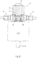
Fig. 8 oder9 in Draufsicht und - Fig. 11 und 12
- die Zuführeinheit im Vertikalschnitt entlang der Linien XI-XI und XII-XII in
Fig. 10 . - In den
Figuren 1 bis 4 ist zunächst ein erstes Ausführungsbeispiel dargestellt. InFig. 1 ist dabei in schematischer Darstellung eine erfindungsgemäße Vorrichtung zur Herstellung von Kunststoffformkörpern aus einem Gemisch zweier Komponenten A, B dargestellt. Eine dieser Komponenten härtet mittels UV-Licht aus und muss daher vor der eigentlichen UV-Behandlung zuverlässig lichtgeschützt gelagert und aufbereitet werden.Fig. 1 zeigt zunächst zwei Dosiermischer 1 und 2, welche jeweils mit einem Rührwerk 3 ausgestattet sind. Über Einlassventile 4 werden die beiden Komponenten A und B aus (nicht dargestellten) jeweiligen Vorratsbehältern in die Dosiermischer 1 und 2 gegeben, in denen sie unter Vakuum mittels einer Vakuumpumpe 5 über einen vorgegebenen Zeitraum entgast werden, damit sich keinerlei Luftbläschen mehr in den einzelnen Komponenten befinden. Unterhalb der Dosiermischer 1 und 2 ist jeweils eine Dosierpumpe 6 angeordnet, welche die beiden entgasten Komponenten A und B im gewünschten Verhältnis einem statischen Mischer 7 zuführen, in dem aus den beiden entgasten einzelnen Komponenten A und B ein Verbundgemisch AB entsteht. Dieses Verbundgemisch AB wird, gleichfalls mittels der Dosierpumpe 6, einer Gießform 8 zugeführt, der eine UV-Licht-Bestrahlungseinheit 9 vorgeschaltet ist. Ein Absperrventil 10 stoppt den weiteren Zufluss des Verbundgemisches AB nach vollständiger Füllung der Gießform 8. In der gesamten Leitung des Gemisches AB bis zum Erreichen der UV-Licht-Bestrahlungseinheit 9 muss zuverlässig jeglicher Lichtkontakt vermieden werden. - In
Fig. 2 sind die Gießform 8 und die UV-Licht-Bestrahlungseinheit 9 vergrößert dargestellt. Man erkennt zunächst, dass die Gießform 8 aus zwei Gießformhälften 8A und 8B besteht, welche mittels einer nicht näher bezeichneten Schließeinheit geöffnet und geschlossen werden können. Die vorgeschaltete UV-Licht-Bestrahlungseinheit 9 weist ein Gehäuse 11 auf, durch das das Verbundgemisch AB geführt wird und in dessen Innerem die UV-Licht-Bestrahlung des Gemisches AB stattfindet. -
Fig. 3 zeigt eine detailliertere UV-Licht-Bestrahlungseinheit 9, in der erkennbar ist, dass das Gehäuse 11 mit einem Eingang und einem Ausgang für das Gemisch AB versehen ist und dass das Gemisch AB durch ein Glasrohr 12 durch das Gehäuse 11 fließt. Ein UV-Strahler 13 ist in einem weiteren Glasrohr 14 im Inneren des Gehäuses 11 angeordnet. Ein erster Lüfter 15 sorgt für eine Kühlung des Gehäuseinneren und ein zweiter Lüfter 16 kühlt den UV-Strahler 13 im Inneren des Glasrohres 14. Auf diese Weise lässt sich das Gehäuse 11 und der UV-Strahler 13 separat und unabhängig voneinander kühlen. - Zur besseren Verteilung und Einbringung der UV-Strahlen in das Verbundgemisch AB ist das Gehäuse 11 in seinem Inneren mit Spiegelreflektoren 17 versehen, welche im dargestellten und insoweit bevorzugten Ausführungsbeispiel eine ellipsenförmige Anordnung aufweisen, wie insbesondere aus
Fig. 4 zu entnehmen ist. Das Glasrohr 12 zur Masseführung befindet sich dabei im ersten Brennpunkt der Ellipse und der UV-Strahler 13 im zweiten Brennpunkt, so dass durch die Spiegelreflektoren eine äußerst gleichmäßige Beaufschlagung des durch das Glasrohr 12 geförderten Verbundgemisches AB erfolgt, um eine gleichmäßige Einbringung der UV-Strahlen in das Gemisch AB zu erreichen. - Aus
Fig. 4 geht ferner hervor, dass das Gehäuse 11 im Bereich des Glasrohres 12 für das Gemisch AB eine Öffnungsebene O aufweist. Zum Schutz gegen UV-Strahlung und Blendung bei geöffnetem Gehäuse 11 ist eine Blendschutzkappe 18 vorgesehen, welche mit einem beispielsweise pneumatischen Antrieb 19 vor den UV-Strahler verfahrbar ist, wie durch den Doppelpfeil inFig. 3 angedeutet ist. - Aus
Fig. 2 ist zu entnehmen, dass die Öffnungsebene O im bevorzugten Ausführungsbeispiel mit der Trennebene der Gießform 8 fluchtet. Zweckmäßiger Weise erfolgt das Öffnen des Gehäuses 11 gemeinsam mit der Öffnung der Gießform 8, indem die UV-Licht-Bestrahlungseinheit 9 mit ihren einzelnen Bestandteilen 11A bzw. 11B an den jeweiligen Gießformhälften 8A bzw. 8B befestigt sind. - Aus
Fig. 3 ist ferner ersichtlich, dass zur Überwachung der UV-Bestrahlungsstrecke am Gehäuse ein Pyrometer 20 zur Temperaturmessung und -überwachung, ein UV-Intensitätssensor 21 zur Messung der UV-Strahlungsintensität und ein Widerstandthermometer 22 angeordnet sind. - Die
Figuren 5 bis 7 zeigen ein weiteres Ausführungsbeispiel einer UV-Licht-Bestrahlungseinheit 9, wobei die UV-Lichtquelle (nicht dargestellt) außerhalb der UV-Licht-Bestrahlungseinheit angeordnet ist und zur Übertragung des UV-Lichts von der UV-Lichtquelle zur Behandlungsstrecke Lichtwellenleiter 24 verwendet werden. -
Fig. 5 zeigt, dass mehrere, im dargestellten Ausführungsbeispiel vier, Lichtwellenleiter 24 sternförmig in ein Gehäuse 25 führen, in dessen Innerem eine senkrecht zu den Lichtwellenleitern 24 verlaufende UV-Behandlungsstrecke 26 verläuft. Zweckmäßiger Weise ist auch das Gehäuse 25 teilbar. Die beiden Gehäuseteile 25A und 25B sind besonders gut im Vertikalschnitt gemäßFig. 6 zu erkennen. Das Gehäuse 25 weist an seiner Unterseite einen Adapter 27 für eine Gießdüse (nicht dargestellt) und an seiner Oberseite einen Adapter 28 für die Gießform (nicht dargestellt) auf. - Auch bei der zweiten Ausführungsform ist die UV-Behandlungsstrecke 26 von einem Glasrohr 29 umgeben, welches im dargestellten und insoweit bevorzugten Ausführungsbeispiel in nicht näher bezeichneten O-Ringen im Gehäuse 25 gehalten ist. Dies ist besonders zweckmäßig, da die Enden der Lichtwellenleiter 24 unmittelbar vor der durch die O-Ringe zentrierten Wandung des Glasrohres 29 enden. Durch das Öffnen der beiden Teile 25A, 25B des Gehäuses 25 wird eine einfache Reinigung der UV-Behandlungsstrecke 26 ermöglicht.
- Im Ausführungsbeispiel gemäß
Fig. 6 ist erkennbar, dass jeweils vier Lichtwellenleiter 24, welche in sternförmiger Anordnung radial in das Gehäuse 25 münden, übereinander angeordnet sind und so mehrere Behandlungsebenen bilden. In der Ausführung gemäßFig. 6 sind drei übereinander angeordnete Behandlungsebenen E1, E2 und E3 dargestellt. Durch eine Aufteilung des Gehäuses in einzelne "Ringe" wird je nach gewünschter Leistung ein modularer Aufbau der erfindungsgemäßen Vorrichtung ermöglicht. -
Fig. 7 zeigt in perspektivischer Darstellung das Gehäuse 25 in geöffneter Stellung, wobei die beiden Gehäuseteile 25A und 25B und das Glasrohr 29 der UV-Behandlungsstrecke 26 gut erkennbar sind. Nicht dargestellt ist, dass eine vorgeschaltete Regeleinheit dafür sorgt, dass auch bei dieser Ausführungsvariante die UV-Strahlungsintensität der jeweiligen Durchflussmenge des Gemisches angepasst wird. - Ein weiteres Ausführungsbeispiel einer erfindungsgemäßen Vorrichtung ist in
Fig. 8 dargestellt. Dort ist die Verarbeitung eines Dreikomponenten-Silikons beschrieben. Dabei entsprechen die beiden linken Vorratsbehälter 1 und 2 sowie deren Ausrüstung mit Rührwerk 3 und Vakuumpumpe 5 zur Entgasung der Darstellung ausFig. 1 . Daneben befindet sich ein weiterer Vorratsbehälter 30 mit einer Komponente C, an dessen Ausgang sich wiederum eine Dosierpumpe 6 befindet. Als dritte Komponente C kann bevorzugt eine Farbe dienen, welche es ermöglicht, das Formteil aus dem Gemisch AB beliebig einzufärben. - Die abgehende Leitung mit der Komponente C wird nachfolgend in zwei Teilströme C1 und C2 geteilt und in einer Zuführeinheit 31 dem Gemisch AB zugemischt, welches dort bereits die UV-Licht-Bestrahlungseinheit 9 verlassen hat. Die Zuführeinheit 31 ist dabei unmittelbar zwischen der UV-Licht-Bestrahlungseinheit 9 und der Gießform 8 angeordnet, wie auch aus der vergrößerten Darstellung in
Fig. 9 hervorgeht. - Der Aufbau der Zuführeinheit 31 lässt sich besonders gut den
Figuren 10 bis 12 entnehmen.Fig. 10 zeigt zunächst die Zuführeinheit 31 in einer Draufsicht, man erkennt deutlich die Zufuhr der beiden Teilströme C1 und C2 der Komponente C. Der eigentliche Aufbau der Zuführeinheit 31 geht deutlich aus der ihren Vertikalschnitt zeigendenFig. 11 hervor. Man erkennt zunächst ein Gehäuse 32, welches unten einen Einlass 33 und einen darüber angeordneten statischen Mischer 34 aufweist. Im Bereich des Einlasses münden zwei Einspritzdüsen 35, durch die die beiden Teilströme C1 und C2 der dritten Komponente C dem bereits UV-Licht aktivierten Gemisch AB zugeführt werden. Bevorzugt sind die Einspritzdüsen 35 mit Schnellkupplungen versehen, die eine einfache Montage sowie eine gute Reinigung und Wartung gestatten. Darüber hinaus verhindern die Schnellkupplungen zuverlässig, dass Luft in die Komponente C gelangen kann. Im statischen Mischer 34 erfolgt dann eine innige Mischung des Gemisches ABC, bevor das Gemisch durch den als Dichtkugel ausgeführten Adapter 36 unmittelbar der oberhalb der Zuführeinheit 31 angeordneten Gießform 8 zugeführt wird. -
Fig. 12 zeigt schließlich in einem weiteren Vertikalschnitt der Zuführeinheit 31 entlang der Linie XII-XII ausFig. 10 , dass im unteren Teil des Gehäuses 32 beidseitig Magnete 37 angeordnet sind, die den unteren Teil mit dem oberen Teil des Gehäuses 32 zusammenhalten. Im dargestellten und insoweit bevorzugten Ausführungsbeispiel sind die Magnete 37 als Quadermagnete ausgeführt. Ferner sind am Fuße des Gehäuses 32 noch zwei weitere Magnete 38 vorgesehen, die bevorzugt als Topfmagnete mit einer mittigen Bohrung ausgeführt sind und ein einfaches Aufstecken auf die Oberseite der UV-Licht-Bestrahlungseinheit 9 bzw. 25 erlauben. Es versteht sich, dass die Glasrohre 12 bzw. 29 der jeweils eingesetzten UV-Licht-Bestrahlungseinheit 9 bzw. 25 so weit nach oben ragen, dass sie dicht mit dem Einlass 33 des Gehäuses 32 der Zuführeinheit 31 abschließen. - Es ist klar, dass die in den Figuren gezeigten Ausführungsformen nur beispielhafte Ausgestaltungen darstellen, die die vorliegende Erfindung nicht beschränken sollen. Vielmehr ist gerade durch das zweite Ausführungsbeispiel der UV-Licht-Bestrahlungseinheit gezeigt, dass ein modularer Aufbau der UV-Behandlungsstrecke die erfindungsgemäße Vorrichtung optimal an beliebige Anwendungsfälle und unterschiedlichste Gießformen jedweder Größe und Geometrie anpassen lässt.
Claims (31)
- Verfahren zur Herstellung von Kunststoffformkörpern aus einem Gemisch mehrerer Komponenten, von denen wenigstens eine mittels UV-Licht aushärtet, wobei die lichtempfindliche Komponente ohne Lichteinfall gelagert und in einem Dosiermischer vakuumaufbereitet wird und wobei die Komponenten über Dosierpumpen im richtigen Mischungsverhältnis in einem statischen Mischer ohne Lichtkontakt gemischt werden,
wobei das Gemisch mittels der Dosierpumpen einer UV-Licht-Bestrahlungseinheit zugeführt, dort durch UV-Strahlung bestrahlt wird und anschließend in die Gießform fließt, wo es endgültig aushärtet, und wobei die UV-Strahlenintensität im Verhältnis zur Durchflussmenge des Gemisches geregelt wird. - Verfahren nach Anspruch 1,
dadurch gekennzeichnet, dass
das Verbundgemisch ein UV-aushärtendes Zweikomponenten-Silikon ist. - Verfahren nach Anspruch 1,
dadurch gekennzeichnet, dass
das Verbundgemisch ein UV-aushärtendes Dreikomponenten-Silikon ist. - Verfahren nach einem der Ansprüche 1 bis 3,
dadurch gekennzeichnet, dass
die Temperatur des Gemisches in der UV-Licht-Bestrahlungseinheit überwacht wird. - Verfahren nach einem der Ansprüche 1 bis 4,
dadurch gekennzeichnet, dass
die UV-Licht-Bestrahlungseinheit zu Reinigungs- oder Wartungszwecken geöffnet und/oder geteilt werden kann. - Verfahren nach einem der Ansprüche 3 bis 5,
dadurch gekennzeichnet, dass
die Herstellung mittels einer Dreikomponenten-Vakuum-Misch- und Dosieranlage erfolgt, in der vor der UV-Licht-Bestrahlung zwei der Komponenten gemischt werden und zwischen der Bestrahlung und dem Eintritt in die Gießform das Zumischen der dritten Komponente erfolgt. - Vorrichtung zur Herstellung von Kunststoffformkörpern aus einem Gemisch mehrerer Komponenten (A, B, C), von denen wenigstens eine mittels UV-Licht aushärtet, mit einer Gießform (8) und mit wenigstens einer UV-Licht-Bestrahlungseinheit (9) zum Aktivieren des lichtempfindlichen Gemisches (AB),
dadurch gekennzeichnet, dass
die wenigstens eine UV-Licht-Bestrahlungseinheit (9) ein umschlossenes Gehäuse (11) mit einem Eingang und einem Ausgang für das Gemisch (AB) aufweist, dass das Gemisch (AB) durch ein Glasrohr (12) durch das Gehäuse (11) fließt, dass zur Messung der UV-Strahlungsintensität im Gehäuse (11) ein UV-Intensitätssensor (21) angeordnet ist, dass die UV-Lichtquelle als UV-Strahler (13) ausgebildet ist, und dass die Vorrichtung mehrere der Anzahl der Komponenten (A, B, C) entsprechende Dosiermischer (1, 2, 30) zur Vakuumaufbereitung der einzelnen Komponenten (A, B, C), wobei jedem Dosiermischer (1, 2, 30) eine Dosierpumpe (6) nachgeordnet ist, und wenigstens einen statischen Mischer (7) aufweist. - Vorrichtung nach Anspruch 7,
dadurch gekennzeichnet, dass
die wenigstens eine UV-Licht-Bestrahlungseinheit (9) unmittelbar vor der Gießform (8) angeordnet ist. - Vorrichtung nach Anspruch 7,
dadurch gekennzeichnet, dass sich zwischen der UV-Licht-Bestrahlungseinheit (9) und der Gießform (8) eine Zuführeinheit (31) zum Einspritzen einer Komponente (C) in den Fluss des Gemisches (AB) befindet. - Vorrichtung nach Anspruch 9,
dadurch gekennzeichnet, dass
die Zuführeinheit (31) mehrere über ihren Umfang verteilt angeordnete seitliche Einspritzdüsen (35) aufweist und dass der Fluss der Komponente (C) vor der Zuführeinheit (31) aufgeteilt ist. - Vorrichtung nach Anspruch 10,
dadurch gekennzeichnet, dass
zwei Einspritzdüsen (35) auf gegenüber liegenden Seiten der Zuführeinheit (31) vorgesehen sind. - Vorrichtung nach Anspruch 10 oder 11,
dadurch gekennzeichnet, dass
die Einspritzdüsen (35) auswechselbar ausgestaltet sind. - Vorrichtung nach einem der Ansprüche 9 bis 12,
dadurch gekennzeichnet, dass
hinter der Zuführeinheit (31) ein statischer Mischer (35) angeordnet ist. - Vorrichtung nach einem der Ansprüche 9 bis 13,
dadurch gekennzeichnet, dass
zum Zusammenhalten des Gehäuses (32) der Zuführeinheit (31) Magnete (37) vorgesehen sind. - Vorrichtung nach einem der Ansprüche 9 bis 14,
dadurch gekennzeichnet, dass
die Zuführeinheit (31) auf die UV-Licht-Bestrahlungseinheit (9) mit Hilfe von Magneten (38) aufsteckbar ist. - Vorrichtung nach Anspruch 7,
dadurch gekennzeichnet, dass
der UV-Strahler (13) von einem Glasrohr (14) umgeben ist. - Vorrichtung nach den Ansprüchen 7 und 16,
dadurch gekennzeichnet, dass
das Gehäuse (11) der UV-Licht-Bestrahlungseinheit (9) und/oder das Glasrohr (14) des UV-Strahlers (13) jeweils einen eigenständigen Lüfter (15, 16) aufweist. - Vorrichtung nach einem der Ansprüche 1 bis 17,
dadurch gekennzeichnet, dass
das Gehäuse (11) innen zur besseren Verteilung und Einbringung der UV-Strahlen mit Spiegelreflektoren (17) versehen ist. - Vorrichtung nach Anspruch 18,
dadurch gekennzeichnet, dass
die Spiegelreflektoren (17) eine ellipsenförmige Anordnung aufweisen und dass das Glasrohr (12) für das Gemisch (AB) im ersten Brennpunkt und der UV-Strahler (13) im zweiten Brennpunkt der Ellipse angeordnet sind. - Vorrichtung nach einem der Ansprüche 8 bis 19,
dadurch gekennzeichnet, dass
das Gehäuse (11) im Bereich des Glasrohres (12) für das Gemisch (AB) eine Öffnungsebene (O) aufweist. - Vorrichtung nach Anspruch 20,
dadurch gekennzeichnet, dass
die Öffnungsebene (O) mit der Trennebene der Gießform (8) fluchtet und das Gehäuse (11) gemeinsam mit der Gießform (8) geöffnet wird. - Vorrichtung nach einem der Ansprüche 19 bis 21,
dadurch gekennzeichnet, dass
zum Schutz gegen UV-Strahlung und Blendung bei geöffnetem Gehäuse (11) eine Blendschutzkappe (18) vor den UV-Strahler (13) bewegbar ist. - Vorrichtung nach einem der Ansprüche 7 bis 22,
dadurch gekennzeichnet, dass
zur Temperaturmessung und -überwachung im Gehäuse (11) ein Pyrometer, insbesondere ein Miniatur-Pyrometer (20) angeordnet ist. - Vorrichtung nach einem der Ansprüche 7 bis 23,
dadurch gekennzeichnet, dass
im Gehäuse ein Widerstandsthermometer (22) vorhanden ist. - Vorrichtung nach Anspruch 7 oder 8,
dadurch gekennzeichnet, dass
die UV-Lichtquelle außerhalb der UV-Licht-Bestrahlungseinheit angeordnet ist und dass Lichtwellenleiter (24) zur Übertragung des UV-Lichts von der UV-Lichtquelle zur Bestrahlungsstrecke vorhanden sind. - Vorrichtung nach Anspruch 25,
dadurch gekennzeichnet, dass
die Lichtwellenleiter (24) in einem eine Behandlungsstrecke (26) bildenden Gehäuse (25) münden und bis an ein Glasrohr (29 für das Gemisch heranreichen. - Vorrichtung nach Anspruch 26,
dadurch gekennzeichnet, dass
die Lichtwellenleiter (24) sternförmig zur Mitte der Behandlungsstrecke (26) ausgerichtet angeordnet sind. - Vorrichtung nach Anspruch 27,
dadurch gekennzeichnet, dass
zur Erhöhung der UV-Strahlungsleistung mehrere sternförmige Lichtwellenleiter in parallelen Ebenen (E1, E2, E3) übereinander angeordnet sind. - Vorrichtung nach Anspruch 26,
dadurch gekennzeichnet, dass
das Gehäuse (25) im Bereich der Behandlungsstrecke (26) für das Gemisch (AB) eine Öffnungsebene (O) aufweist. - Vorrichtung nach Anspruch 29,
dadurch gekennzeichnet, dass
das Gehäuse (25) zwei Halbschalen (25A, 25B) aufweist, von denen jeweils eine Halbschale (25A bzw. 25B) an einer darüber angeordneten Gießformhälfte befestigt ist. - Vorrichtung nach einem der Ansprüche 28 bis 30,
dadurch gekennzeichnet, dass
das Gehäuse (25) einen bezüglich der Ebenen (E1, E2, E3) der Lichtwellenleiter (24) modularen Aufbau aufweist.
Applications Claiming Priority (1)
| Application Number | Priority Date | Filing Date | Title |
|---|---|---|---|
| DE102013102236.7A DE102013102236A1 (de) | 2013-03-06 | 2013-03-06 | Verfahren und Vorrichtung zur Herstellung von Kunststoffformkörpern aus einem Gemisch mehrerer Komponenten |
Publications (2)
| Publication Number | Publication Date |
|---|---|
| EP2774748A1 EP2774748A1 (de) | 2014-09-10 |
| EP2774748B1 true EP2774748B1 (de) | 2017-09-27 |
Family
ID=50272311
Family Applications (1)
| Application Number | Title | Priority Date | Filing Date |
|---|---|---|---|
| EP14157998.7A Active EP2774748B1 (de) | 2013-03-06 | 2014-03-06 | Verfahren und vorrichtung zur herstellung von kunststoffformkörpern aus einem gemisch mehrerer komponenten |
Country Status (2)
| Country | Link |
|---|---|
| EP (1) | EP2774748B1 (de) |
| DE (2) | DE202013101500U1 (de) |
Families Citing this family (2)
| Publication number | Priority date | Publication date | Assignee | Title |
|---|---|---|---|---|
| DE102017100353A1 (de) | 2017-01-10 | 2018-07-12 | Vogel Moulds And Machines Ag | Vorrichtung und Verfahren zur Herstellung von Kunststoffformkörpern aus einem Gemisch mehrerer Komponenten |
| DE102022200748A1 (de) * | 2022-01-24 | 2023-07-27 | Raumedic Ag | Verfahren zur Konnektierung zweier Silikon-Schlauchabschnitte sowie pharmazeutisches Medientransferverfahren mit einem derartigen Konnektierungsverfahren und Vorrichtung zum Durchführen des Verfahrens |
Citations (4)
| Publication number | Priority date | Publication date | Assignee | Title |
|---|---|---|---|---|
| EP0616843A2 (de) * | 1993-03-12 | 1994-09-28 | AT&T Corp. | System zum kontinuierlichen Überwachen des Aushärtungsenergiepegels innerhalb einer Aushärtungsvorrichtung |
| US20010008485A1 (en) * | 2000-01-18 | 2001-07-19 | Hiroyuki Fuji | Spot light-source device excited by electromagentic energy |
| DE19647922C2 (de) * | 1996-11-20 | 2003-03-13 | Huebers Verfahrenstech | Verfahren und Vorrichtung zur Erwärmung von viskosen Massen, insbesondere Gießharz oder anderen Materialien mit vergleichbaren dipolaren Eigenschaften, durch Mikrowellenergie |
| EP2674284A1 (de) * | 2012-06-06 | 2013-12-18 | Astracast PLC | Verbesserungen bei der Herstellung von Artikeln wie Waschbecken |
Family Cites Families (4)
| Publication number | Priority date | Publication date | Assignee | Title |
|---|---|---|---|---|
| DE4119415A1 (de) * | 1991-06-13 | 1992-12-17 | Huebers Verfahrenstech | Verfahren zum transport und zur aufbereitung von und zur beschickung einer giessanlage mit giessharz, sowie vorrichtung zur ausfuehrung des verfahrens |
| DE19961990B4 (de) * | 1999-12-22 | 2005-05-25 | Erwin Behr Automotive Gmbh | Verfahren und Vorrichtung zur Beschichtung eines Innenausbauteils für Kraftfahrzeuge |
| DE102004036573A1 (de) * | 2004-07-28 | 2006-03-23 | Ge Bayer Silicones Gmbh & Co. Kg | Verwendung lichtaktivierbarer, härtbarer Silikonzusammensetzungen zur Herstellung von dickwandigen Formartikeln oder dickwandigen Beschichtungen |
| AT13189U1 (de) * | 2012-06-04 | 2013-08-15 | Elast Kunststoffverarbeitungs Gmbh Und Co Keg | Verfahren und Vorrichtung zur Verarbeitung von flüssigen Silikonmassen in Spritzgussmaschine und Spritzgussmaschine |
-
2013
- 2013-03-06 DE DE202013101500U patent/DE202013101500U1/de not_active Expired - Lifetime
- 2013-03-06 DE DE102013102236.7A patent/DE102013102236A1/de not_active Ceased
-
2014
- 2014-03-06 EP EP14157998.7A patent/EP2774748B1/de active Active
Patent Citations (4)
| Publication number | Priority date | Publication date | Assignee | Title |
|---|---|---|---|---|
| EP0616843A2 (de) * | 1993-03-12 | 1994-09-28 | AT&T Corp. | System zum kontinuierlichen Überwachen des Aushärtungsenergiepegels innerhalb einer Aushärtungsvorrichtung |
| DE19647922C2 (de) * | 1996-11-20 | 2003-03-13 | Huebers Verfahrenstech | Verfahren und Vorrichtung zur Erwärmung von viskosen Massen, insbesondere Gießharz oder anderen Materialien mit vergleichbaren dipolaren Eigenschaften, durch Mikrowellenergie |
| US20010008485A1 (en) * | 2000-01-18 | 2001-07-19 | Hiroyuki Fuji | Spot light-source device excited by electromagentic energy |
| EP2674284A1 (de) * | 2012-06-06 | 2013-12-18 | Astracast PLC | Verbesserungen bei der Herstellung von Artikeln wie Waschbecken |
Also Published As
| Publication number | Publication date |
|---|---|
| DE202013101500U1 (de) | 2013-06-18 |
| EP2774748A1 (de) | 2014-09-10 |
| DE102013102236A1 (de) | 2014-09-11 |
Similar Documents
| Publication | Publication Date | Title |
|---|---|---|
| WO1994008770A1 (de) | Temperierbares werkzeug bzw. temperierbare form zur herstellung von kunststofformteilen und verfahren zur herstellung solcher werkzeuge bzw. formen | |
| DE102012200594A1 (de) | Form und Verfahren zur Herstellung eines Fahrradrahmens hergestellt aus recyclebarem Polymer | |
| DE4210687A1 (de) | Vorrichtung für die Abgabe zähflüssiger, aushärtender Stoffe, sowie Verfahren zum Betrieb einer derartigen Vorrichtung | |
| AT13189U1 (de) | Verfahren und Vorrichtung zur Verarbeitung von flüssigen Silikonmassen in Spritzgussmaschine und Spritzgussmaschine | |
| EP2774748A1 (de) | Verfahren und Vorrichtung zur Herstellung von Kunststoffformkörpern aus einem Gemisch mehrerer Komponenten | |
| EP2558265B1 (de) | Verfahren zum herstellen von ringförmigen, zug- oder druckbelasteten formkörpern aus kunststoff und armatur für unter druck stehende fluide | |
| EP1863628B1 (de) | Traganordnung für ein extrusionswerkzeug und verfahren zur extrusion eines gegenstandes | |
| DE102008026892B4 (de) | Extrudermischteil, Verfahren zum Mischen von Kunststoffschmelze unter Einsatz eines Extrudermischteils | |
| DE102012112491A1 (de) | Vorrichtung und Verfahren zum Herstellen von Kunststoffvorformlingen aus einem thermoplastischen Kunststoff | |
| DE10223374B4 (de) | Vorrichtung zum universellen Einfärben von kontinuierlich unter Druck strömenden, in einer Plastifiziereinheit plastifizierten viskosen Massen | |
| DE19646394C1 (de) | Extrusionsanlage und Verfahren zur Extrusion mit minimierten Farbwechselzeiten | |
| DE102011079435A1 (de) | Kunststoffspritzguss-Werkstück und Verfahren zum Herstellen eines Kunststoffspritzguss-Werkstücks | |
| DE102015009377A1 (de) | Mischwerkzeug | |
| DE4320848A1 (de) | Vorrichtung für die Abgabe zähflüssiger, aushärtender Stoffe | |
| DE102014115809B3 (de) | Vorrichtung und Verfahren zum Spritzgießen von Faserverbundkunststoffformteilen | |
| DE4421405C1 (de) | Verfahren zum Spritzgießen von Formteilen aus Kunststoff | |
| DE202012103569U1 (de) | Vorrichtung zur Herstellung textilverstärkter Kunststoffbauteile | |
| DE2902007C2 (de) | Kunststoff-Rohrleitung mit einer Einrichtung für die Tropfbewässerung | |
| DE19525540C1 (de) | Vorrichtung zum Absperren einer Schmelze insbesondere aus Kunststoff | |
| EP3520887B1 (de) | Vorrichtung zum aufeinanderfolgenden einbringen von additiven in ein polymergranulat und verwendung der vorrichtung | |
| DE60318008T2 (de) | Verfahren und Vorrichtung zur diskontinuierlichen Herstellung von Rohrverbindungen mit geringem Verzug | |
| DE4004980A1 (de) | Vorrichtung zum extrudieren eines profilierten formstrangs | |
| DE202004019566U1 (de) | Führungskammer als Anfahrhilfe | |
| DE4245074B4 (de) | Vorrichtung für die Abgabe zähflüssiger, aushärtender Stoffe, sowie Verfahren zum Betrieb einer derartigen Vorrichtung | |
| EP2105201A1 (de) | Verfahren und Vorrichtung zur Mischung von viskosen oder plastischen Medien |
Legal Events
| Date | Code | Title | Description |
|---|---|---|---|
| PUAI | Public reference made under article 153(3) epc to a published international application that has entered the european phase |
Free format text: ORIGINAL CODE: 0009012 |
|
| 17P | Request for examination filed |
Effective date: 20140306 |
|
| AK | Designated contracting states |
Kind code of ref document: A1 Designated state(s): AL AT BE BG CH CY CZ DE DK EE ES FI FR GB GR HR HU IE IS IT LI LT LU LV MC MK MT NL NO PL PT RO RS SE SI SK SM TR |
|
| AX | Request for extension of the european patent |
Extension state: BA ME |
|
| R17P | Request for examination filed (corrected) |
Effective date: 20150309 |
|
| RBV | Designated contracting states (corrected) |
Designated state(s): AL AT BE BG CH CY CZ DE DK EE ES FI FR GB GR HR HU IE IS IT LI LT LU LV MC MK MT NL NO PL PT RO RS SE SI SK SM TR |
|
| 17Q | First examination report despatched |
Effective date: 20150908 |
|
| GRAP | Despatch of communication of intention to grant a patent |
Free format text: ORIGINAL CODE: EPIDOSNIGR1 |
|
| INTG | Intention to grant announced |
Effective date: 20170420 |
|
| GRAS | Grant fee paid |
Free format text: ORIGINAL CODE: EPIDOSNIGR3 |
|
| GRAA | (expected) grant |
Free format text: ORIGINAL CODE: 0009210 |
|
| AK | Designated contracting states |
Kind code of ref document: B1 Designated state(s): AL AT BE BG CH CY CZ DE DK EE ES FI FR GB GR HR HU IE IS IT LI LT LU LV MC MK MT NL NO PL PT RO RS SE SI SK SM TR |
|
| REG | Reference to a national code |
Ref country code: GB Ref legal event code: FG4D Free format text: NOT ENGLISH |
|
| REG | Reference to a national code |
Ref country code: CH Ref legal event code: EP |
|
| REG | Reference to a national code |
Ref country code: CH Ref legal event code: NV Representative=s name: SCHMAUDER AND PARTNER AG PATENT- UND MARKENANW, CH |
|
| REG | Reference to a national code |
Ref country code: AT Ref legal event code: REF Ref document number: 931580 Country of ref document: AT Kind code of ref document: T Effective date: 20171015 |
|
| REG | Reference to a national code |
Ref country code: IE Ref legal event code: FG4D Free format text: LANGUAGE OF EP DOCUMENT: GERMAN |
|
| REG | Reference to a national code |
Ref country code: DE Ref legal event code: R096 Ref document number: 502014005559 Country of ref document: DE |
|
| PG25 | Lapsed in a contracting state [announced via postgrant information from national office to epo] |
Ref country code: NO Free format text: LAPSE BECAUSE OF FAILURE TO SUBMIT A TRANSLATION OF THE DESCRIPTION OR TO PAY THE FEE WITHIN THE PRESCRIBED TIME-LIMIT Effective date: 20171227 Ref country code: HR Free format text: LAPSE BECAUSE OF FAILURE TO SUBMIT A TRANSLATION OF THE DESCRIPTION OR TO PAY THE FEE WITHIN THE PRESCRIBED TIME-LIMIT Effective date: 20170927 Ref country code: FI Free format text: LAPSE BECAUSE OF FAILURE TO SUBMIT A TRANSLATION OF THE DESCRIPTION OR TO PAY THE FEE WITHIN THE PRESCRIBED TIME-LIMIT Effective date: 20170927 Ref country code: SE Free format text: LAPSE BECAUSE OF FAILURE TO SUBMIT A TRANSLATION OF THE DESCRIPTION OR TO PAY THE FEE WITHIN THE PRESCRIBED TIME-LIMIT Effective date: 20170927 Ref country code: LT Free format text: LAPSE BECAUSE OF FAILURE TO SUBMIT A TRANSLATION OF THE DESCRIPTION OR TO PAY THE FEE WITHIN THE PRESCRIBED TIME-LIMIT Effective date: 20170927 |
|
| REG | Reference to a national code |
Ref country code: NL Ref legal event code: MP Effective date: 20170927 |
|
| REG | Reference to a national code |
Ref country code: LT Ref legal event code: MG4D |
|
| PG25 | Lapsed in a contracting state [announced via postgrant information from national office to epo] |
Ref country code: BG Free format text: LAPSE BECAUSE OF FAILURE TO SUBMIT A TRANSLATION OF THE DESCRIPTION OR TO PAY THE FEE WITHIN THE PRESCRIBED TIME-LIMIT Effective date: 20171227 Ref country code: RS Free format text: LAPSE BECAUSE OF FAILURE TO SUBMIT A TRANSLATION OF THE DESCRIPTION OR TO PAY THE FEE WITHIN THE PRESCRIBED TIME-LIMIT Effective date: 20170927 Ref country code: GR Free format text: LAPSE BECAUSE OF FAILURE TO SUBMIT A TRANSLATION OF THE DESCRIPTION OR TO PAY THE FEE WITHIN THE PRESCRIBED TIME-LIMIT Effective date: 20171228 Ref country code: LV Free format text: LAPSE BECAUSE OF FAILURE TO SUBMIT A TRANSLATION OF THE DESCRIPTION OR TO PAY THE FEE WITHIN THE PRESCRIBED TIME-LIMIT Effective date: 20170927 |
|
| PG25 | Lapsed in a contracting state [announced via postgrant information from national office to epo] |
Ref country code: NL Free format text: LAPSE BECAUSE OF FAILURE TO SUBMIT A TRANSLATION OF THE DESCRIPTION OR TO PAY THE FEE WITHIN THE PRESCRIBED TIME-LIMIT Effective date: 20170927 |
|
| PG25 | Lapsed in a contracting state [announced via postgrant information from national office to epo] |
Ref country code: CZ Free format text: LAPSE BECAUSE OF FAILURE TO SUBMIT A TRANSLATION OF THE DESCRIPTION OR TO PAY THE FEE WITHIN THE PRESCRIBED TIME-LIMIT Effective date: 20170927 Ref country code: ES Free format text: LAPSE BECAUSE OF FAILURE TO SUBMIT A TRANSLATION OF THE DESCRIPTION OR TO PAY THE FEE WITHIN THE PRESCRIBED TIME-LIMIT Effective date: 20170927 Ref country code: RO Free format text: LAPSE BECAUSE OF FAILURE TO SUBMIT A TRANSLATION OF THE DESCRIPTION OR TO PAY THE FEE WITHIN THE PRESCRIBED TIME-LIMIT Effective date: 20170927 |
|
| PG25 | Lapsed in a contracting state [announced via postgrant information from national office to epo] |
Ref country code: SM Free format text: LAPSE BECAUSE OF FAILURE TO SUBMIT A TRANSLATION OF THE DESCRIPTION OR TO PAY THE FEE WITHIN THE PRESCRIBED TIME-LIMIT Effective date: 20170927 Ref country code: IS Free format text: LAPSE BECAUSE OF FAILURE TO SUBMIT A TRANSLATION OF THE DESCRIPTION OR TO PAY THE FEE WITHIN THE PRESCRIBED TIME-LIMIT Effective date: 20180127 Ref country code: EE Free format text: LAPSE BECAUSE OF FAILURE TO SUBMIT A TRANSLATION OF THE DESCRIPTION OR TO PAY THE FEE WITHIN THE PRESCRIBED TIME-LIMIT Effective date: 20170927 Ref country code: IT Free format text: LAPSE BECAUSE OF FAILURE TO SUBMIT A TRANSLATION OF THE DESCRIPTION OR TO PAY THE FEE WITHIN THE PRESCRIBED TIME-LIMIT Effective date: 20170927 Ref country code: SK Free format text: LAPSE BECAUSE OF FAILURE TO SUBMIT A TRANSLATION OF THE DESCRIPTION OR TO PAY THE FEE WITHIN THE PRESCRIBED TIME-LIMIT Effective date: 20170927 |
|
| REG | Reference to a national code |
Ref country code: DE Ref legal event code: R097 Ref document number: 502014005559 Country of ref document: DE |
|
| PG25 | Lapsed in a contracting state [announced via postgrant information from national office to epo] |
Ref country code: DK Free format text: LAPSE BECAUSE OF FAILURE TO SUBMIT A TRANSLATION OF THE DESCRIPTION OR TO PAY THE FEE WITHIN THE PRESCRIBED TIME-LIMIT Effective date: 20170927 |
|
| PLBE | No opposition filed within time limit |
Free format text: ORIGINAL CODE: 0009261 |
|
| STAA | Information on the status of an ep patent application or granted ep patent |
Free format text: STATUS: NO OPPOSITION FILED WITHIN TIME LIMIT |
|
| PG25 | Lapsed in a contracting state [announced via postgrant information from national office to epo] |
Ref country code: PL Free format text: LAPSE BECAUSE OF FAILURE TO SUBMIT A TRANSLATION OF THE DESCRIPTION OR TO PAY THE FEE WITHIN THE PRESCRIBED TIME-LIMIT Effective date: 20170927 |
|
| 26N | No opposition filed |
Effective date: 20180628 |
|
| PG25 | Lapsed in a contracting state [announced via postgrant information from national office to epo] |
Ref country code: MT Free format text: LAPSE BECAUSE OF FAILURE TO SUBMIT A TRANSLATION OF THE DESCRIPTION OR TO PAY THE FEE WITHIN THE PRESCRIBED TIME-LIMIT Effective date: 20170927 |
|
| GBPC | Gb: european patent ceased through non-payment of renewal fee |
Effective date: 20180306 |
|
| PG25 | Lapsed in a contracting state [announced via postgrant information from national office to epo] |
Ref country code: SI Free format text: LAPSE BECAUSE OF FAILURE TO SUBMIT A TRANSLATION OF THE DESCRIPTION OR TO PAY THE FEE WITHIN THE PRESCRIBED TIME-LIMIT Effective date: 20170927 Ref country code: MC Free format text: LAPSE BECAUSE OF FAILURE TO SUBMIT A TRANSLATION OF THE DESCRIPTION OR TO PAY THE FEE WITHIN THE PRESCRIBED TIME-LIMIT Effective date: 20170927 |
|
| REG | Reference to a national code |
Ref country code: BE Ref legal event code: MM Effective date: 20180331 |
|
| REG | Reference to a national code |
Ref country code: IE Ref legal event code: MM4A |
|
| PG25 | Lapsed in a contracting state [announced via postgrant information from national office to epo] |
Ref country code: LU Free format text: LAPSE BECAUSE OF NON-PAYMENT OF DUE FEES Effective date: 20180306 |
|
| PG25 | Lapsed in a contracting state [announced via postgrant information from national office to epo] |
Ref country code: IE Free format text: LAPSE BECAUSE OF NON-PAYMENT OF DUE FEES Effective date: 20180306 |
|
| PG25 | Lapsed in a contracting state [announced via postgrant information from national office to epo] |
Ref country code: GB Free format text: LAPSE BECAUSE OF NON-PAYMENT OF DUE FEES Effective date: 20180306 Ref country code: BE Free format text: LAPSE BECAUSE OF NON-PAYMENT OF DUE FEES Effective date: 20180331 |
|
| PG25 | Lapsed in a contracting state [announced via postgrant information from national office to epo] |
Ref country code: FR Free format text: LAPSE BECAUSE OF NON-PAYMENT OF DUE FEES Effective date: 20180331 |
|
| PG25 | Lapsed in a contracting state [announced via postgrant information from national office to epo] |
Ref country code: TR Free format text: LAPSE BECAUSE OF FAILURE TO SUBMIT A TRANSLATION OF THE DESCRIPTION OR TO PAY THE FEE WITHIN THE PRESCRIBED TIME-LIMIT Effective date: 20170927 |
|
| PG25 | Lapsed in a contracting state [announced via postgrant information from national office to epo] |
Ref country code: PT Free format text: LAPSE BECAUSE OF FAILURE TO SUBMIT A TRANSLATION OF THE DESCRIPTION OR TO PAY THE FEE WITHIN THE PRESCRIBED TIME-LIMIT Effective date: 20170927 Ref country code: HU Free format text: LAPSE BECAUSE OF FAILURE TO SUBMIT A TRANSLATION OF THE DESCRIPTION OR TO PAY THE FEE WITHIN THE PRESCRIBED TIME-LIMIT; INVALID AB INITIO Effective date: 20140306 |
|
| PG25 | Lapsed in a contracting state [announced via postgrant information from national office to epo] |
Ref country code: MK Free format text: LAPSE BECAUSE OF NON-PAYMENT OF DUE FEES Effective date: 20170927 Ref country code: CY Free format text: LAPSE BECAUSE OF FAILURE TO SUBMIT A TRANSLATION OF THE DESCRIPTION OR TO PAY THE FEE WITHIN THE PRESCRIBED TIME-LIMIT Effective date: 20170927 |
|
| PG25 | Lapsed in a contracting state [announced via postgrant information from national office to epo] |
Ref country code: AL Free format text: LAPSE BECAUSE OF FAILURE TO SUBMIT A TRANSLATION OF THE DESCRIPTION OR TO PAY THE FEE WITHIN THE PRESCRIBED TIME-LIMIT Effective date: 20170927 |
|
| REG | Reference to a national code |
Ref country code: AT Ref legal event code: MM01 Ref document number: 931580 Country of ref document: AT Kind code of ref document: T Effective date: 20190306 |
|
| PG25 | Lapsed in a contracting state [announced via postgrant information from national office to epo] |
Ref country code: AT Free format text: LAPSE BECAUSE OF NON-PAYMENT OF DUE FEES Effective date: 20190306 |
|
| REG | Reference to a national code |
Ref country code: DE Ref legal event code: R082 Ref document number: 502014005559 Country of ref document: DE Representative=s name: WITTE, WELLER & PARTNER PATENTANWAELTE MBB, DE |
|
| PGFP | Annual fee paid to national office [announced via postgrant information from national office to epo] |
Ref country code: DE Payment date: 20230330 Year of fee payment: 10 |
|
| PGFP | Annual fee paid to national office [announced via postgrant information from national office to epo] |
Ref country code: CH Payment date: 20230429 Year of fee payment: 10 |
|
| REG | Reference to a national code |
Ref country code: DE Ref legal event code: R119 Ref document number: 502014005559 Country of ref document: DE |
|
| REG | Reference to a national code |
Ref country code: CH Ref legal event code: PL |
|
| PG25 | Lapsed in a contracting state [announced via postgrant information from national office to epo] |
Ref country code: DE Free format text: LAPSE BECAUSE OF NON-PAYMENT OF DUE FEES Effective date: 20241001 |
|
| PG25 | Lapsed in a contracting state [announced via postgrant information from national office to epo] |
Ref country code: DE Free format text: LAPSE BECAUSE OF NON-PAYMENT OF DUE FEES Effective date: 20241001 Ref country code: CH Free format text: LAPSE BECAUSE OF NON-PAYMENT OF DUE FEES Effective date: 20240331 |