EP0614195B1 - Fret resistant fuel rod with zirconium oxide layer - Google Patents
Fret resistant fuel rod with zirconium oxide layer Download PDFInfo
- Publication number
- EP0614195B1 EP0614195B1 EP94301368A EP94301368A EP0614195B1 EP 0614195 B1 EP0614195 B1 EP 0614195B1 EP 94301368 A EP94301368 A EP 94301368A EP 94301368 A EP94301368 A EP 94301368A EP 0614195 B1 EP0614195 B1 EP 0614195B1
- Authority
- EP
- European Patent Office
- Prior art keywords
- tube
- fuel
- heating
- rods
- forming
- Prior art date
- Legal status (The legal status is an assumption and is not a legal conclusion. Google has not performed a legal analysis and makes no representation as to the accuracy of the status listed.)
- Revoked
Links
Images

Classifications
-
- G—PHYSICS
- G21—NUCLEAR PHYSICS; NUCLEAR ENGINEERING
- G21C—NUCLEAR REACTORS
- G21C3/00—Reactor fuel elements and their assemblies; Selection of substances for use as reactor fuel elements
- G21C3/02—Fuel elements
- G21C3/04—Constructional details
- G21C3/06—Casings; Jackets
- G21C3/07—Casings; Jackets characterised by their material, e.g. alloys
-
- Y—GENERAL TAGGING OF NEW TECHNOLOGICAL DEVELOPMENTS; GENERAL TAGGING OF CROSS-SECTIONAL TECHNOLOGIES SPANNING OVER SEVERAL SECTIONS OF THE IPC; TECHNICAL SUBJECTS COVERED BY FORMER USPC CROSS-REFERENCE ART COLLECTIONS [XRACs] AND DIGESTS
- Y02—TECHNOLOGIES OR APPLICATIONS FOR MITIGATION OR ADAPTATION AGAINST CLIMATE CHANGE
- Y02E—REDUCTION OF GREENHOUSE GAS [GHG] EMISSIONS, RELATED TO ENERGY GENERATION, TRANSMISSION OR DISTRIBUTION
- Y02E30/00—Energy generation of nuclear origin
- Y02E30/30—Nuclear fission reactors
Definitions
- the invention relates to the field of nuclear fuel rod structures.
- the invention involves application of a hard, dense and wear-resistant layer of zirconium oxide (ZrO 2 ) to a zirconium-based alloy fuel cladding for improving resistance to fretting caused by debris lodged in a nuclear fuel assembly.
- the ZrO 2 layer is thermally grown in situ along at least the end portion of the fuel rod at and adjacent the lower grid of the fuel assembly and substantially reduces fretting damage.
- Fuel reliability is among the highest priorities in operation of a pressurized water nuclear power plant.
- coolant water is heated in a pressure vessel disposed along a primary coolant circuit by nuclear fuel in the form of elongated fuel rods arranged in vertical arrays in fuel assemblies.
- Each fuel rod comprises cylindrical pellets of enriched uranium stacked in a hollow tube typically made of a zirconium alloy.
- the fuel rods are grouped in fuel assembly structures that enable a number of the fuel rods to be handled as a unit.
- the fuel assemblies are mounted in the reactor vessel with the fuel rods elongated vertically and closely spaced.
- the fuel rods produce heat with nuclear fission at a rate that is controlled via neutron absorbing control rods that are inserted or removed from positions in the fuel assemblies.
- the fuel rods heat the primary coolant, producing a vigorous and turbulent upward flow of the coolant over the fuel rods due to convection.
- the fuel rod cladding material is typically a zirconium alloy such as Zircaloy.
- Zirconium is particularly useful because of its ready availability, good ductility, resistance to radiation damage, low thermal-neutron absorption cross section, and excellent corrosion resistance in pressurized water up to 350°C.
- Zirconium is a highly active metal that, like aluminum, seems passive because a stable and cohesive thin oxide film forms on the surface in the presence of air or water.
- the oxide film chemically protects the zirconium metal.
- oxide forms in the damaged area, provided oxygen is present to sustain the reaction.
- US Patent 4,100,020 - Andrews a nuclear fuel rod is provided with a coating of a transition metal oxide on the inside of the fuel rod cladding tube.
- the transition metal oxide releases oxygen to ensure that oxygen will remain available during the useful life of the fuel rod to re-form the protective ZrO 2 coating.
- Other disclosures relating to the formation of an oxide layer on the inside of a zirconium cladding tube include US Patents 4,609,524 - Ferrari and 4,233,086 - Vesterlund.
- the fuel assemblies support the fuel rods by means of a series of spaced panels or grids, connected by thimble tubes running parallel to the fuel rods.
- the grids have resilient structures bearing against the fuel rods, and otherwise are open to allow the coolant to flow through the fuel assembly.
- the top and bottom end panels of the fuel assembly are known as nozzles and also are structured to allow coolant to flow through the fuel assembly. It is known to provide the bottom nozzle with small holes as a means to filter out any debris that is larger than the diameter of the holes from entering the fuel assembly. The holes are sized to maximize the tradeoff between effectiveness of the bottom nozzle as a debris filter and the resistance of the bottom nozzle to flow of the coolant.
- the bottom nozzle prevents large debris that potentially could cause substantial damage to the fuel rods from entering the fuel assembly.
- smaller debris can pass through the bottom nozzle. It is not advantageous to reduce the size of the holes in the bottom nozzle further and thereby filter smaller debris from the coolant, due to the additional resistance to flow of the coolant. Therefore, debris resistant bottom nozzle structures cannot completely eliminate the problem of fretting damage to the fuel rods.
- Debris that is small enough to pass through the bottom nozzle may be blocked by or lodged in the grids supporting the fuel rods. Whereas the debris is captured at and below the lowermost grid supporting the fuel rods, the turbulent coolant flow agitates the debris and frets against the fuel rod cladding.
- the method disclosed in the said document includes providing a zirconium alloy component, reacting at least a portion of an outer surface of said component at about atmospheric pressure with a material selected from the group consisting of carbon compounds suitable for forming a carbide, cyano or carbonate compounds suitable for forming an oxide, air or oxygen for forming an oxide and combinations of the forgoing, at a temperature below 500°C to avoid changes in the metallurgical characteristics of the zirconium alloy component, the reaction producing a black wear resistant layer on said surface.
- the present inventors have determined from evaluations of debris related fuel rod failures that most of the failures occur early in the first cycle of irradiation. Due to debris fretting, the failures typically occur at a point on the fuel rod below the location of the bottom grid. With heating during operation of the reactor, and in the presence of the water coolant, the surface of the fuel rod becomes increasingly oxidized, improving the resistance of the fuel rod to fretting damage over time. Therefore, according to the invention, the fuel rod is pre-oxidized in the critical area at and below the bottom grid, to provide preliminary additional protection to fretting damage. This is accomplished by heating in the presence of oxygen, according to the treatment processes disclosed in detail hereinafter.
- zirconium alloy nuclear fuel rods preliminarily treating zirconium alloy nuclear fuel rods to form a thickened oxide layer to protect the outer surface of the rods against fretting damage due to debris captured by the fuel assembly and agitated against the fuel rod at and below the bottom supporting grid of the fuel assembly.
- This is accomplished by heating the rod in an oxygen containing atmosphere and thereby forming a thickened zirconium oxide (ZrO 2 ) surface layer between the bottom grid and the end of the fuel rod.
- the thicker portion can be 2 to 15 microns in thickness, extending 10.16 to 20.32 cm (four to eight inches) from the end of the tube, to a point at which the rod is supported by a receptacle in the bottom grid.
- the portion to be protected is heated to a temperature of 600 to 870°C (1100 to 1600°F) for up to one hour, for example by electromagnetic induction heating, furnace heating, electrical resistance heating and heating by application of laser radiation.
- the portion can be enclosed in a vessel during heating, in a gaseous environment with a gaseous pressure and/or oxygen concentration greater than normal atmospheric, or in oxygen with an inert gas.
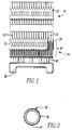
- FIGURE 1 is an elevation view showing a nuclear fuel assembly according to the invention, with a fret resistant fuel rod with zirconium oxide layer.
- FIGURE 2 is a section view through one of the nuclear fuel rods, showing the protective oxide layer.
- FIGURE 3 is a schematic illustration showing growing a protective oxide layer in atmospheric oxygen, using a furnace arrangement.
- FIGURE 4 is a schematic illustration showing growing a protective oxide layer in non-atmospheric pressure and/or gas content conditions.
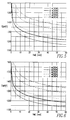
- FIGURE 5 is a graph showing variations of treatment time and temperature for forming a protective oxide layer according to the invention for a Zircaloy-4 tube in air.
- FIGURE 6 is a graph showing variations of treatment time and temperature for forming a protective oxide layer according to the invention for a Zirlo tube in air.
- FIGURE 7 is a schematic illustration of electromagnetic induction heating according to the invention for forming the oxide layer.
- FIGURE 8 is a schematic illustration of electrical resistance heating for forming the oxide layer.
- FIGURE 9 is a schematic illustration showing forming the oxide layer by application of laser radiation.
- debris-induced failure of a nuclear fuel rod 20 is inhibited by forming a thickened layer of zirconium oxide (ZrO 2 ) along the bottom four to eight inches of a fuel rod, i.e., in the area of the fuel rod 20 below the bottom grid 32 of the fuel assembly structure 34.
- This protective layer 24 is hard and dense, and is provided on the fuel rod 20 preliminarily, before the first cycle of irradiation. Together with a debris filtering bottom nozzle structure 36, this extra oxide thickness provides a high degree of protection against debris fretting damage leading to leakage of the nuclear fuel rods (20).
- FIGURE 1 shows the lower area of a nuclear fuel assembly 34.
- the assembly 34 has a bottom nozzle 36 that is open to passage of the coolant in an upward direction.
- a number of supporting grids 32 support the fuel rods 20 and are disposed at a space from the nozzle 36.
- the grids 32 are generally open work frames attached to one another and to the top and bottom nozzles (only the bottom nozzle 36 being shown) by thimble tubes.
- the grids 32 have a plurality of receptacles for the rods 20, formed by bows in the sheet material of the grid, that hold the fuel rods 20 in closely spaced parallel vertical orientation.
- the grids 32 also allow coolant to flow through over the rods 20, however, the grids 32 also trap debris in the area of the rods 20, especially between the bottom nozzle 36 and the lowermost grid 32.
- Each of the nuclear fuel rods 20 includes fissionable fuel in a cladding tube 28 defining an elongated hollow shaft of a zirconium alloy material such as Zircaloy or Zirlo.
- Zirconium oxidizes in air
- the cladding tube or hollow shaft 28 has a zirconium oxide surface coating 22.
- the oxide coating is thickened in the critical area between the bottom nozzle 36 and the lowermost grid 32.
- the coating 22 includes a portion 24 on an outer surface of the tube 28, adjacent the grid support position 26, which portion 24 is substantially thicker than the zirconium oxide surface coating 22 along the remaining length of the tube 28.
- the portion 24 of zirconium oxide on the outer surface of the tube 28 that is substantially thicker preferably extends from the grid support position 26 of the bottom grid 32, to the bottom end of the tube 28, where an end plug 42 closes the tube and confines the nuclear fuel therein.
- the pre-oxidation of the nuclear fuel rod 20 along this portion 24 is accomplished on a pickled, polished or as-manufactured zirconium based alloy tube or cladding 28, preferably that has been pre-welded with the end plug 42 at the bottom of the fuel rod 20.
- the thickened ZrO 2 layer 24 can be grown by exposing the rod 20 to normal atmospheric gas concentrations (i.e., 20% oxygen and 80% nitrogen) and pressure. Alternatively, oxygen exposure can be raised, e.g., by using a mixture of oxygen and an inert gas such as argon or helium and elevated pressure. Time, temperature and concentration of oxygen exposure preferably are chosen to build up a protective layer 24 of at least 2 to 15 microns in thickness.
- the protective layer 24 is provided along the fuel rod 20 at and below the point 26 at which the rod will be carried by a grid 32 of the fuel assembly 34, in particular at and below the area of the bottom grid 32 or in the bottom 4 to 8 inches (10 to 20cm) of the fuel rod 20.
- the relative positions of the protective oxide layer 24, bottom grid 32 and bottom filtering nozzle 36 are shown in FIGURE 1, and the protective layer 24 is shown sectionally in FIGURE 2.
- the heating can be accomplished in a variety of ways, including, for example, electromagnetic induction heating, furnace heating, electrical resistance heating and heating by application of laser radiation. Heating can be accomplished at increased gaseous pressure via an autoclave.
- the cladding 28 is heated to a temperature of 600 to 870°C (1,100 to 1,600°F) for up to one hour at atmospheric pressure and oxygen concentration, to provide a protective coating 24 as shown in FIGURE 2.
- FIGURE 3 illustrates a furnace type heating arrangement.
- the bottom ends of the zirconium alloy fuel rods 20 to be treated are passed through a furnace 52 in normal atmospheric oxygen concentration.
- Each fuel rod 20 has its end plug 42 pre-welded.
- the rod 20 can be heated to a high temperature for a short time or to a lower temperature for a longer time in order to grow the zirconium oxide layer 22 to the required thickness in the area 24 of the rod 20 that will be disposed at and below the bottom grid 32 of the fuel assembly 34.
- the rods 20 to be treated by heating can be arranged on a support (not shown) such that their ends extend into the furnace 52, and moved laterally of their longitudinal extension and/or rolled during the process.
- the atmosphere around the fuel rods 20 during heat treating must contain oxygen but the oxygen need not be at normal atmospheric gas concentrations and pressures. Increasing the concentration of oxygen and the gas pressure shortens the time needed to form the protective oxide layer 24.
- the rods 20 can be heated in a gaseous environment of oxygen and inert gas to form the thickened ZrO 2 layer 24.
- the rods 20 can be partly confined by the furnace 52 to form a vessel 54 that encompasses at least the ends of the rods 20 in the area 24 to be treated.
- FIGURE 5 is a graph showing variations of treatment time and temperature as needed for forming a protective oxide layer 24 on a Zircaloy-4 tube 28 in air.
- FIGURE 6 is a corresponding graph showing the time and temperature needed for forming a protective oxide layer on a Zirlo tube in air.
- the protective oxide layer 24 preferably is 3 to 9 microns in thickness, and can be formed by heating for the time and to the temperatures shown.
- FIGURES 7-9 illustrate some alternative methods for heating the rods 20 in the area 24 to be treated.
- FIGURE 7 shows heating via electromagnetic induction. A current is induced in the zirconium alloy of the rod by applying an alternating current to a coil 62, and resistive heating from the induced current brings the rod 20 to a temperature at which the formation of the oxide layer is promoted.
- Electrical resistance heating can also be employed more directly by attaching electrical conductors on either side of the zone 24, as shown in FIGURE 8.
- a high current, low voltage source 66 is coupled between the end 42 of the rod 20 and a point 26 on the rod that will reside in the fuel assembly 34 adjacent the bottom grid 32.
- the electric energy thus coupled to the rod 20 is dissipated as heat, for promoting oxidation.
- FIGURE 9 illustrates heating the rod 20 by laser radiation for forming the oxide layer.
- a CO 2 or Nd-YAG laser 68 can be scanned along the outer surface of the rod 20 to locally heat the zirconium alloy material and thus promote oxidation.
- the treated rod 20 is installed in the fuel assembly 34 such that the protectively oxidized end is disposed at and below the bottom grid 32 of the fuel assembly 34.
- Debris (not shown) that passes upwardly with the coolant through the bottom nozzle 36, which preferably is a debris filtering type, is captured between the bottom nozzle 36 and the bottom grid 32, or perhaps lodges in the bottom grid 32.
- the debris is agitated by the upward flow of coolant.
- the protective oxide layer 24 is hard and dense, and protects the zirconium alloy material from fretting damage, particularly during the early irradiation cycles of the fuel rod 20 before the outer surface of the rod 20 becomes generally oxidized by operational heating in the coolant water of the nuclear reactor, to a comparable oxidation thickness.
Landscapes
- Engineering & Computer Science (AREA)
- Physics & Mathematics (AREA)
- Metallurgy (AREA)
- Plasma & Fusion (AREA)
- General Engineering & Computer Science (AREA)
- High Energy & Nuclear Physics (AREA)
- Monitoring And Testing Of Nuclear Reactors (AREA)
- Other Surface Treatments For Metallic Materials (AREA)
- Fuel Cell (AREA)
- Chemical Treatment Of Metals (AREA)
Applications Claiming Priority (2)
| Application Number | Priority Date | Filing Date | Title |
|---|---|---|---|
| US2536193A | 1993-03-02 | 1993-03-02 | |
| US25361 | 1993-03-02 |
Publications (2)
| Publication Number | Publication Date |
|---|---|
| EP0614195A1 EP0614195A1 (en) | 1994-09-07 |
| EP0614195B1 true EP0614195B1 (en) | 1999-04-21 |
Family
ID=21825581
Family Applications (1)
| Application Number | Title | Priority Date | Filing Date |
|---|---|---|---|
| EP94301368A Revoked EP0614195B1 (en) | 1993-03-02 | 1994-02-25 | Fret resistant fuel rod with zirconium oxide layer |
Country Status (7)
| Country | Link |
|---|---|
| EP (1) | EP0614195B1 (enExample) |
| JP (1) | JPH06289171A (enExample) |
| KR (1) | KR940022587A (enExample) |
| CZ (1) | CZ285357B6 (enExample) |
| DE (1) | DE69417941T2 (enExample) |
| ES (1) | ES2130353T3 (enExample) |
| TW (1) | TW239215B (enExample) |
Cited By (1)
| Publication number | Priority date | Publication date | Assignee | Title |
|---|---|---|---|---|
| WO2023200695A1 (en) * | 2022-04-11 | 2023-10-19 | Clarke Michael T | Formation of surface oxide coatings for zirconium and zirconium based alloys |
Families Citing this family (16)
| Publication number | Priority date | Publication date | Assignee | Title |
|---|---|---|---|---|
| US6512806B2 (en) | 1996-02-23 | 2003-01-28 | Westinghouse Atom Ab | Component designed for use in a light water reactor, and a method for the manufacture of such a component |
| SE509382C2 (sv) * | 1996-02-23 | 1999-01-18 | Asea Atom Ab | Komponent som är utformad för användning i en lättvattenreaktor samt förfarande för att framställa en sådan komponent |
| DE19721080C1 (de) * | 1997-05-20 | 1998-10-01 | Siemens Ag | Verfahren zum Überdecken eines Bauteiles mit einer korrosionshemmenden Fremdoxidschicht und mit einer solchen Fremdoxidschicht überdecktes Bauteil |
| DE19910379C1 (de) * | 1999-03-09 | 2000-06-29 | Siemens Ag | Brennelement für einen Kernreaktor |
| DE19944509A1 (de) * | 1999-09-16 | 2001-04-19 | Siemens Ag | Kernbrennelementbauteile mit Schutzschichtsystem |
| DE10010135A1 (de) * | 2000-03-03 | 2001-09-13 | Siemens Ag | Bauteil eines Kernreaktor-Brennelements mit einem Mittel zur Verringerung der Wasserstoffaufnahme und/oder der Shadow-Korrosion und entsprechende Herstellung |
| US6813329B1 (en) * | 2003-06-12 | 2004-11-02 | Westinghouse Electric Copmany Llc | Crud-resistant nuclear fuel cladding |
| KR100443624B1 (ko) * | 2003-09-05 | 2004-08-11 | 연천군 | 청정 오이 재배용 봉투 및 이를 이용한 오이 재배 방법 |
| US20110180184A1 (en) | 2006-12-15 | 2011-07-28 | Daniel Reese Lutz | Surface laser treatment of zr-alloy fuel bundle material |
| KR101405396B1 (ko) * | 2012-06-25 | 2014-06-10 | 한국수력원자력 주식회사 | 표면에 혼합층을 포함하는 코팅층이 형성된 지르코늄 합금 및 이의 제조방법 |
| US10060018B2 (en) * | 2013-05-28 | 2018-08-28 | Westinghouse Electric Company Llc | Kinetically applied gradated Zr-Al-C ceramic or Ti-Al-C ceramic or amorphous or semi-amorphous stainless steel with nuclear grade zirconium alloy metal structure |
| US20150107072A1 (en) * | 2013-10-22 | 2015-04-23 | Kazim Ozbaysal | Fatigue resistant turbine through bolt |
| CN105002545A (zh) * | 2014-04-24 | 2015-10-28 | 北京师范大学 | 一种用于核燃料棒锆合金包壳激光焊接接头的保护膜制备方法 |
| US12372116B1 (en) * | 2020-03-02 | 2025-07-29 | Honeywell Federal Manufacturing & Technologies, Llc | System and method for lubricating surfaces of parts |
| CN112037950B (zh) * | 2020-09-24 | 2022-02-11 | 中国核动力研究设计院 | 一种燃料棒裂变产物释放模拟装置及其使用方法 |
| US20230368931A1 (en) * | 2022-05-10 | 2023-11-16 | Westinghouse Electric Company Llc | Fuel cladding covered by a mesh |
Family Cites Families (5)
| Publication number | Priority date | Publication date | Assignee | Title |
|---|---|---|---|---|
| GB1306939A (en) * | 1969-07-08 | 1973-02-14 | British Nuclear Fuels Ltd | Nuclear reactors |
| JPS62177489A (ja) * | 1986-01-31 | 1987-08-04 | 株式会社東芝 | 耐摩耗,耐食部材およびその製造方法 |
| FR2607616B1 (fr) * | 1986-12-01 | 1990-05-18 | Framatome Sa | Assemblage combustible nucleaire a gaines revetues et procede de revetement de telles gaines |
| US5171520A (en) * | 1990-09-04 | 1992-12-15 | Combustion Engineering, Inc. | Wear resistant coating for fuel cladding |
| US5265137A (en) * | 1990-11-26 | 1993-11-23 | Siemens Power Corporation | Wear resistant nuclear fuel assembly components |
-
1994
- 1994-02-25 ES ES94301368T patent/ES2130353T3/es not_active Expired - Lifetime
- 1994-02-25 DE DE69417941T patent/DE69417941T2/de not_active Revoked
- 1994-02-25 EP EP94301368A patent/EP0614195B1/en not_active Revoked
- 1994-02-28 CZ CZ94447A patent/CZ285357B6/cs not_active IP Right Cessation
- 1994-02-28 KR KR1019940003708A patent/KR940022587A/ko not_active Ceased
- 1994-03-01 JP JP6031136A patent/JPH06289171A/ja active Pending
- 1994-05-03 TW TW083104004A patent/TW239215B/zh not_active IP Right Cessation
Cited By (1)
| Publication number | Priority date | Publication date | Assignee | Title |
|---|---|---|---|---|
| WO2023200695A1 (en) * | 2022-04-11 | 2023-10-19 | Clarke Michael T | Formation of surface oxide coatings for zirconium and zirconium based alloys |
Also Published As
| Publication number | Publication date |
|---|---|
| ES2130353T3 (es) | 1999-07-01 |
| CZ44794A3 (en) | 1994-09-14 |
| KR940022587A (ko) | 1994-10-21 |
| JPH06289171A (ja) | 1994-10-18 |
| TW239215B (enExample) | 1995-01-21 |
| EP0614195A1 (en) | 1994-09-07 |
| DE69417941T2 (de) | 1999-09-30 |
| CZ285357B6 (cs) | 1999-07-14 |
| DE69417941D1 (de) | 1999-05-27 |
Similar Documents
| Publication | Publication Date | Title |
|---|---|---|
| EP0614195B1 (en) | Fret resistant fuel rod with zirconium oxide layer | |
| EP0560857B1 (en) | Wear resistant nuclear fuel assembly components | |
| US5075075A (en) | Nuclear reactor core having nuclear fuel and composite burnable absorber arranged for power peaking and moderator temperature coefficient control | |
| Pahl et al. | Irradiation behavior of metallic fast reactor fuels | |
| JP2009258126A (ja) | 原子炉の炉心の反応を調節するためのクラスター、クラスターの吸収ロッド、及び吸収ロッドを摩耗に対して保護するための方法 | |
| CN108140434B (zh) | 锆合金包壳上的腐蚀和磨损抵抗性涂层 | |
| JPH0915382A (ja) | 応力腐食割れを防ぐための金属の放射線誘発パラジウム・ドーピング | |
| US5436947A (en) | Zirconium alloy fuel cladding | |
| US5147598A (en) | Nuclear reactor core having nuclear fuel and composite burnable absorber arranged for power peaking and moderator temperature coefficient control | |
| WO2017098228A1 (en) | Rectangular nuclear reactor core | |
| KR100380127B1 (ko) | 고온수내의낮은부식전위를유지하기위한산화막전기전도도의조절 | |
| WO2000026921A3 (en) | Rodlet absorbing members for use with spent fuel | |
| LeSurf¹ | Zirconium Alloy | |
| KR19990072604A (ko) | 복합부재및이를이용한연료집합체 | |
| US20230368931A1 (en) | Fuel cladding covered by a mesh | |
| RU2387030C1 (ru) | Микротвэл легководного ядерного реактора | |
| Ferrari et al. | Fuel-Element Experience in Pressurized-Water Reactors | |
| EP0611128A1 (en) | Spacer to suppress departure from nucleate boiling | |
| MALTSEV et al. | STATUS AND POSSIBILITY OF FUEL AND STRUCTURAL MATERIALS EXPERIMENTAL IRRADIATION IN BN-600 REACTOR. STAGES OF BN-600 REACTOR CORE DEVELOPMENT BA VASILJEV, AI ZINOVJEV, AI STAROVEROV Experimental Machine Building Bureau, XA9848039 | |
| Chang et al. | A simplified refueling scheme for nuclear heating reactor | |
| RU2059299C1 (ru) | Ядерный реактор и способ очистки тепловыделяющих сборок ядерного реактора | |
| JP2002311178A (ja) | 原子炉構造材、原子炉、ガス冷却直接サイクル高速炉及び核融合炉 | |
| JPH06201876A (ja) | 原子炉の炉心構造 | |
| JPH0821888A (ja) | 被覆管及びジルカロイ被覆管を製造する方法 | |
| JPS61286789A (ja) | 燃料集合体 |
Legal Events
| Date | Code | Title | Description |
|---|---|---|---|
| PUAI | Public reference made under article 153(3) epc to a published international application that has entered the european phase |
Free format text: ORIGINAL CODE: 0009012 |
|
| AK | Designated contracting states |
Kind code of ref document: A1 Designated state(s): BE CH DE ES FR GB LI SE |
|
| 17P | Request for examination filed |
Effective date: 19950224 |
|
| 17Q | First examination report despatched |
Effective date: 19960129 |
|
| GRAG | Despatch of communication of intention to grant |
Free format text: ORIGINAL CODE: EPIDOS AGRA |
|
| GRAG | Despatch of communication of intention to grant |
Free format text: ORIGINAL CODE: EPIDOS AGRA |
|
| GRAH | Despatch of communication of intention to grant a patent |
Free format text: ORIGINAL CODE: EPIDOS IGRA |
|
| GRAH | Despatch of communication of intention to grant a patent |
Free format text: ORIGINAL CODE: EPIDOS IGRA |
|
| GRAH | Despatch of communication of intention to grant a patent |
Free format text: ORIGINAL CODE: EPIDOS IGRA |
|
| GRAA | (expected) grant |
Free format text: ORIGINAL CODE: 0009210 |
|
| AK | Designated contracting states |
Kind code of ref document: B1 Designated state(s): BE CH DE ES FR GB LI SE |
|
| REG | Reference to a national code |
Ref country code: CH Ref legal event code: NV Representative=s name: A. BRAUN, BRAUN, HERITIER, ESCHMANN AG PATENTANWAE Ref country code: CH Ref legal event code: EP |
|
| REF | Corresponds to: |
Ref document number: 69417941 Country of ref document: DE Date of ref document: 19990527 |
|
| ET | Fr: translation filed | ||
| REG | Reference to a national code |
Ref country code: ES Ref legal event code: FG2A Ref document number: 2130353 Country of ref document: ES Kind code of ref document: T3 |
|
| PLBQ | Unpublished change to opponent data |
Free format text: ORIGINAL CODE: EPIDOS OPPO |
|
| PLBI | Opposition filed |
Free format text: ORIGINAL CODE: 0009260 |
|
| PLBF | Reply of patent proprietor to notice(s) of opposition |
Free format text: ORIGINAL CODE: EPIDOS OBSO |
|
| 26 | Opposition filed |
Opponent name: SIEMENS AG Effective date: 20000121 Opponent name: FRAGEMA - G.I.E. Effective date: 20000120 |
|
| PLBF | Reply of patent proprietor to notice(s) of opposition |
Free format text: ORIGINAL CODE: EPIDOS OBSO |
|
| RDAH | Patent revoked |
Free format text: ORIGINAL CODE: EPIDOS REVO |
|
| PGFP | Annual fee paid to national office [announced via postgrant information from national office to epo] |
Ref country code: GB Payment date: 20010104 Year of fee payment: 8 |
|
| PGFP | Annual fee paid to national office [announced via postgrant information from national office to epo] |
Ref country code: SE Payment date: 20010201 Year of fee payment: 8 Ref country code: FR Payment date: 20010201 Year of fee payment: 8 |
|
| PGFP | Annual fee paid to national office [announced via postgrant information from national office to epo] |
Ref country code: ES Payment date: 20010215 Year of fee payment: 8 |
|
| PGFP | Annual fee paid to national office [announced via postgrant information from national office to epo] |
Ref country code: DE Payment date: 20010228 Year of fee payment: 8 |
|
| PGFP | Annual fee paid to national office [announced via postgrant information from national office to epo] |
Ref country code: BE Payment date: 20010313 Year of fee payment: 8 |
|
| PGFP | Annual fee paid to national office [announced via postgrant information from national office to epo] |
Ref country code: CH Payment date: 20010327 Year of fee payment: 8 |
|
| RDAG | Patent revoked |
Free format text: ORIGINAL CODE: 0009271 |
|
| STAA | Information on the status of an ep patent application or granted ep patent |
Free format text: STATUS: PATENT REVOKED |
|
| 27W | Patent revoked |
Effective date: 20001229 |
|
| GBPR | Gb: patent revoked under art. 102 of the ep convention designating the uk as contracting state |
Free format text: 20001229 |
|
| REG | Reference to a national code |
Ref country code: CH Ref legal event code: PL |