EP0612902A2 - Dispositif d'actionnement intérieur pour portes de véhicules - Google Patents
Dispositif d'actionnement intérieur pour portes de véhicules Download PDFInfo
- Publication number
- EP0612902A2 EP0612902A2 EP93105474A EP93105474A EP0612902A2 EP 0612902 A2 EP0612902 A2 EP 0612902A2 EP 93105474 A EP93105474 A EP 93105474A EP 93105474 A EP93105474 A EP 93105474A EP 0612902 A2 EP0612902 A2 EP 0612902A2
- Authority
- EP
- European Patent Office
- Prior art keywords
- bearing
- actuating lever
- bearing part
- axle journal
- movable
- Prior art date
- Legal status (The legal status is an assumption and is not a legal conclusion. Google has not performed a legal analysis and makes no representation as to the accuracy of the status listed.)
- Granted
Links
Images

Classifications
-
- E—FIXED CONSTRUCTIONS
- E05—LOCKS; KEYS; WINDOW OR DOOR FITTINGS; SAFES
- E05B—LOCKS; ACCESSORIES THEREFOR; HANDCUFFS
- E05B85/00—Details of vehicle locks not provided for in groups E05B77/00 - E05B83/00
- E05B85/10—Handles
- E05B85/12—Inner door handles
-
- E—FIXED CONSTRUCTIONS
- E05—LOCKS; KEYS; WINDOW OR DOOR FITTINGS; SAFES
- E05B—LOCKS; ACCESSORIES THEREFOR; HANDCUFFS
- E05B15/00—Other details of locks; Parts for engagement by bolts of fastening devices
- E05B15/16—Use of special materials for parts of locks
- E05B15/1635—Use of special materials for parts of locks of plastics materials
-
- E—FIXED CONSTRUCTIONS
- E05—LOCKS; KEYS; WINDOW OR DOOR FITTINGS; SAFES
- E05B—LOCKS; ACCESSORIES THEREFOR; HANDCUFFS
- E05B79/00—Mounting or connecting vehicle locks or parts thereof
- E05B79/02—Mounting of vehicle locks or parts thereof
- E05B79/06—Mounting of handles, e.g. to the wing or to the lock
Definitions
- the present invention relates to an internal actuating device for vehicle doors, with an actuating lever that is pivotably mounted in a bearing part via a pivot bearing and that can be operatively connected to a door lock for opening the door, the bearing part being in particular non-detachably fastened to a door interior trim.
- the bearing part is usually permanently attached to a surface of a door interior trim with a flat peripheral edge, either glued or welded (friction welding).
- the operating lever can no longer be dismantled without further notice (which, however, may be necessary, for example, in the event of damage for the purpose of replacement).
- a pivot axis provided for the pivot bearing of the actuating lever as a continuous axle bolt lies in the area of an opening of the door trim and approximately in the plane of the door trim or within a plane range defined by the thickness of the trim and therefore in the state of the door trim connected to the door trim Not part of the stock disassembled more, ie can be pulled out of their axle holder.
- the present invention is based on the object, based on the described prior art, to provide a generic internal actuation device in which both the assembly and the disassembly of the actuation lever also in the assembled, i.e. attached to the door panel condition of the bearing part, are very easy.
- the actuating lever is detachably connected or connectable to the bearing part via spring means that are resiliently movable in the axial direction of the pivot bearing and form components of the pivot bearing. Due to this advantageous embodiment, the actuating lever only needs to be “locked” in the bearing part, so that the assembly is considerably simplified. Since there is no longer a continuous pivot axis to be mounted by axial insertion, any assembly or disassembly of the actuating lever can also take place when the bearing part is connected to the door trim. An exchange of the actuating lever is possible at any time without the bearing part having to be removed from the panel; Damage occurring in this way is thus also reliably avoided.
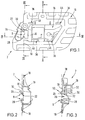
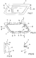
- An internal actuation device mainly consists of three components, a bearing part 2 (FIGS. 1 to 4), an actuation lever 4 (FIG. 5) and a cover part 6 (FIGS. 6 to 10).
- the actuating lever 4 is pivotally mounted about a rotation axis 10 in the bearing part 2 via a pivot bearing 8.
- the actuating lever 4 consists of a first lever arm 12, which e.g. is operatively connected via a cable to a door lock (latch lock) for opening the door (unlocking the latch lock), and a second lever arm which forms a handle section 14 accessible from a vehicle interior (see FIG. 5).
- the bearing part 2 consists of an essentially trough-shaped Inner part 16 and a circumferential edge 18 surrounding it and defining a fastening plane.
- the bearing part 2 is permanently attached to a door lining, not shown, by the circumferential edge 18 being firmly bonded, preferably glued or welded, to the surface of the inner lining facing away from a vehicle interior and facing the interior of the door (especially friction welded).
- the pivot bearing 8 is located in the region of a passage opening 20 for the actuating lever 4, this passage opening 20 in turn lying in a region of the peripheral edge 18.
- the actuating lever 4 is now detachably connected or connectable to the bearing part 2 by means of spring means 22 which are resiliently movable in the axial direction of the pivot bearing 8 (direction of the axis of rotation 10) and form components of the pivot bearing 8.
- spring means 22 are resiliently movable in the axial direction of the pivot bearing 8 (direction of the axis of rotation 10) and form components of the pivot bearing 8.
- the pivot bearing 8 preferably has, as the pivot axis, two axially spaced axle journals 26 and 28 connected to the bearing part 2 and each engaging in a bearing opening 24 of the actuating lever 4.
- One of the axle journals namely the respective "upper” axle journal 26 in the drawing figures, forms the latching means 22 according to the invention, in that this axle journal 26 is arranged so as to be resiliently movable in the direction of the axis of rotation 10 such that it moves out of it into the bearing opening 24 of the actuating lever 4 (see FIG. 5) engaging position in a completely outside of the bearing opening 24 assembly or disassembly position is movable.
- this journal 26 is expediently at a free end an elastically flexible spring arm 30 connected to the bearing part 2, which preferably extends from the bearing part 2 in the direction of the vehicle interior, ie approximately perpendicular to the plane of the peripheral edge 18 or the door lining, not shown. This can best be seen in FIG. 3.
- the spring arm 30 is elastically movable in the direction of the double arrow 32 shown in FIG. 3.
- the other, opposite axle journal 28 (in the drawings the "lower” axle journal) is rigid, that is to say it is immovably connected to the bearing part 2.
- the two axle journals 26, 28 are preferably arranged facing one another and consequently engage in the bearing opening 24 of the actuating lever 4 in opposite directions.
- the actuating lever 4 with the area of its bearing opening 24 is practically “between” the axle journals 26, 28 or between their “connection points” of the bearing part 2.
- the locking means 22 can be locked in a position holding the actuating lever 4, preferably by means of a locking part 34, which can be detachably connected to the bearing part, in particular by means of locking connections 36.
- the locking part 34 (see in particular FIGS. 8 and 10) has a receptacle 38 which, when the locking part 34 is connected to the bearing part 2, receives the free end of the spring arm 30 so that the spring arm 30 and thus also the movable axle 26 can be locked against elastic movements, namely the spring arm 30 preferably secured against bending in all directions, ie both in the axial direction of the journal 26 (to secure the mounting of the actuating lever 4), as well as in its transverse direction (whereby a high stability of the pivot bearing is achieved).
- the cover part 6 has a passage opening 40 for the actuating lever 4, the locking part 34, which covers the region of the movable spring arm 30 and on the bearing part, being formed in a region adjacent to this opening 40 2 facing inside the receptacle 38 for the spring arm 30 (see in particular FIGS. 6, 8 and 10).
- the cover part 6 also has a trough-like recess 42 in the region of the grip section 14 of the actuating lever 4, which allows the grip section 14 to reach behind.
- the above-mentioned locking connections 36 for releasably fastening the locking part to the bearing part 2 preferably consist of locking spring arms 44 of the cover part 6 and of corresponding locking openings 46 of the bearing part 2. These are thus “snap-fit connections” which are simple to plug on or clip on of the cover part 6 on the bearing part 2.
- axle journals 26, 28, in the exemplary embodiment shown the lower, stationary axle journal 28 has a shape that tapers conically in the direction of its free end, with the associated bearing opening 24 of the actuating lever 4 also preferably correspondingly is conical.
- This advantageous measure ensures an automatic compensation of axial bearing play, in particular in cooperation with the spring elasticity of the spring arm 30, whereby the actuating lever 4 is always held in the direction of the opposite journal in pretension.
- the actuating lever 4 has a run-up inclined surface 48 in one of the bearing openings 24 provided in the mounting direction for the movable axle journal 26.
- the movable axle journal 26 can also have a run-up inclined surface (not shown) for the actuating lever.
- Dismantling of the actuating lever 4 is also very easily possible by first removing the cover part 6 by releasing the latching connections 36.
- the spring arm 30 can then be bent elastically using a suitable tool, for example a screwdriver, until the axle journal 26 is completely moved out of the bearing opening 24 (disassembly position).
- a suitable tool for example a screwdriver
- the spring arm 30 has an actuating section 50 (see FIG. 3) at its free end for attaching the tool.
- the actuating section 50 can be a depression or - as shown - a web attachment which can be gripped under with a screwdriver blade in order to bend the spring arm into a release position.
- the actuating lever 4 expediently consists of metal, in particular of chromed (high-gloss chrome-plated) steel, while the bearing part 2 and the cover part 6 are preferably made of plastic, namely from a fiber-reinforced plastic based on polyamide 66 or polyamide 6 exist, ie are each formed as one-piece plastic injection molded parts.
- the pivot bearing 8 could also consist of axle journals connected to the actuating lever 4, which would then engage in corresponding bearing openings in the bearing part 2. At least one of the bearing parts (one of the axle journals or one of the bearing openings) would also be axially resiliently movable. All possible design variants for this are therefore within the scope of the invention.
Landscapes
- Lock And Its Accessories (AREA)
Priority Applications (1)
| Application Number | Priority Date | Filing Date | Title |
|---|---|---|---|
| DE9320254U DE9320254U1 (de) | 1992-06-13 | 1993-04-02 | Innenbetätigungsvorrichtung für Fahrzeugtüren |
Applications Claiming Priority (2)
| Application Number | Priority Date | Filing Date | Title |
|---|---|---|---|
| DE4219460 | 1992-06-13 | ||
| DE4219460A DE4219460A1 (de) | 1992-06-13 | 1992-06-13 | Innenbetätigungsvorrichtung für Fahrzeugtüren |
Publications (3)
| Publication Number | Publication Date |
|---|---|
| EP0612902A2 true EP0612902A2 (fr) | 1994-08-31 |
| EP0612902A3 EP0612902A3 (fr) | 1995-02-22 |
| EP0612902B1 EP0612902B1 (fr) | 1997-03-19 |
Family
ID=6460993
Family Applications (1)
| Application Number | Title | Priority Date | Filing Date |
|---|---|---|---|
| EP93105474A Expired - Lifetime EP0612902B1 (fr) | 1992-06-13 | 1993-04-02 | Dispositif d'actionnement intérieur pour portes de véhicules |
Country Status (3)
| Country | Link |
|---|---|
| EP (1) | EP0612902B1 (fr) |
| DE (2) | DE4219460A1 (fr) |
| ES (1) | ES2079331T3 (fr) |
Families Citing this family (1)
| Publication number | Priority date | Publication date | Assignee | Title |
|---|---|---|---|---|
| DE102007057866B4 (de) | 2007-08-01 | 2014-07-03 | Johnson Controls Interiors Gmbh & Co. Kg | Türmodul für Fahrzeugtür und Montageverfahren |
Family Cites Families (2)
| Publication number | Priority date | Publication date | Assignee | Title |
|---|---|---|---|---|
| DE2144756C3 (de) * | 1971-09-07 | 1979-03-15 | Saar-Gummiwerk Gmbh, 6619 Bueschfeld | Fernbetätigungsvorrichtung, insbesondere für Kraftfahrzeugtürschlösser |
| US3795416A (en) * | 1972-06-23 | 1974-03-05 | Itw Ateco Gmbh | Housing for mounting an operating lever for an automotive vehicle door lock |
-
1992
- 1992-06-13 DE DE4219460A patent/DE4219460A1/de not_active Withdrawn
-
1993
- 1993-04-02 DE DE59305876T patent/DE59305876D1/de not_active Expired - Fee Related
- 1993-04-02 ES ES93105474T patent/ES2079331T3/es not_active Expired - Lifetime
- 1993-04-02 EP EP93105474A patent/EP0612902B1/fr not_active Expired - Lifetime
Also Published As
| Publication number | Publication date |
|---|---|
| DE4219460A1 (de) | 1993-12-16 |
| ES2079331T1 (es) | 1996-01-16 |
| DE59305876D1 (de) | 1997-04-24 |
| EP0612902A3 (fr) | 1995-02-22 |
| EP0612902B1 (fr) | 1997-03-19 |
| ES2079331T3 (es) | 1997-06-01 |
Similar Documents
| Publication | Publication Date | Title |
|---|---|---|
| EP0401659A1 (fr) | Fixation d'une bavette de garde-boue | |
| DE4413635A1 (de) | Befestigungsvorrichtung für eine Scheibenwischeranlage | |
| EP0782818B1 (fr) | Systeme d'assemblage par encliquetage pour elements d'un boitier a doigt de blocage integre | |
| EP3131795A1 (fr) | Ensemble essuie-glace | |
| DE60019677T2 (de) | Verstellbare Montageplatte | |
| DE69808398T2 (de) | Fahrzeugspiegel | |
| EP0601446A1 (fr) | Dispositif de verrouillage pour un dispositif de drainage | |
| EP0471989A1 (fr) | Collier de serrage | |
| DE102007035145B4 (de) | Scharnieranordnung für eine Kraftfahrzeugtür | |
| DE10103402A1 (de) | Außenrückblickspiegel eines Kraftfahrzeugs | |
| EP1091132A2 (fr) | Dispositif pour la fixation démontable d'un élément sur une paroi | |
| DE69104682T2 (de) | Befestigungseinrichtung für einen Kühler eines Kraftfahrzeugmotors. | |
| DE10341145A1 (de) | Betriebsmittel zur Sicherung einer Fahrzeugtür | |
| EP0612902B1 (fr) | Dispositif d'actionnement intérieur pour portes de véhicules | |
| DE10126687A1 (de) | Vorrichtung zum Sichern eines Sitzrückens an einem Kraftfahrzeugkörper | |
| DE2836530B2 (de) | Rahmenschloß, insbesondere für Zweiradfahrzeuge | |
| DE10123826A1 (de) | Türaußengriff für die Fahrzeugtür eines Kraftfahrzeuges | |
| EP0611347A1 (fr) | Balai d'essuie-glace destine notamment a nettoyer une vitre d'un vehicule automobile. | |
| DE102013107902A1 (de) | Windabweiser für ein Fahrzeug sowie Fahrzeug mit einem Windabweiser | |
| DE102006059096B4 (de) | Baugruppe zur fahrzeugseitigen Befestigung eines Gurtschlosses | |
| DE202018101859U1 (de) | Vorrichtung zum Fixieren eines Batterietrogs eines Flurförderzeugs | |
| DE19946807B4 (de) | Halterung | |
| DE9320254U1 (de) | Innenbetätigungsvorrichtung für Fahrzeugtüren | |
| DE102021112778A1 (de) | Halter zur Aufnahme einer Leitung, Befestigungsanordnung zur Befestigung einer Leitung an einem Kraftfahrzeug und Verfahren zur Befestigung einer Leitung an einem Kraftfahrzeug | |
| EP0483584B1 (fr) | Accessoire |
Legal Events
| Date | Code | Title | Description |
|---|---|---|---|
| PUAI | Public reference made under article 153(3) epc to a published international application that has entered the european phase |
Free format text: ORIGINAL CODE: 0009012 |
|
| AK | Designated contracting states |
Kind code of ref document: A2 Designated state(s): DE ES FR GB IT |
|
| ITCL | It: translation for ep claims filed |
Representative=s name: ING. A. GIAMBROCONO & C. S.R.L. |
|
| EL | Fr: translation of claims filed | ||
| GBC | Gb: translation of claims filed (gb section 78(7)/1977) | ||
| PUAL | Search report despatched |
Free format text: ORIGINAL CODE: 0009013 |
|
| RHK1 | Main classification (correction) |
Ipc: E05C 21/00 |
|
| RHK1 | Main classification (correction) |
Ipc: E05C 21/00 |
|
| AK | Designated contracting states |
Kind code of ref document: A3 Designated state(s): DE ES FR GB IT |
|
| 17P | Request for examination filed |
Effective date: 19950201 |
|
| GRAG | Despatch of communication of intention to grant |
Free format text: ORIGINAL CODE: EPIDOS AGRA |
|
| 17Q | First examination report despatched |
Effective date: 19960506 |
|
| GRAH | Despatch of communication of intention to grant a patent |
Free format text: ORIGINAL CODE: EPIDOS IGRA |
|
| GRAH | Despatch of communication of intention to grant a patent |
Free format text: ORIGINAL CODE: EPIDOS IGRA |
|
| GRAA | (expected) grant |
Free format text: ORIGINAL CODE: 0009210 |
|
| AK | Designated contracting states |
Kind code of ref document: B1 Designated state(s): DE ES FR GB IT |
|
| GBT | Gb: translation of ep patent filed (gb section 77(6)(a)/1977) |
Effective date: 19970319 |
|
| ITF | It: translation for a ep patent filed | ||
| REF | Corresponds to: |
Ref document number: 59305876 Country of ref document: DE Date of ref document: 19970424 |
|
| ET | Fr: translation filed | ||
| PLBE | No opposition filed within time limit |
Free format text: ORIGINAL CODE: 0009261 |
|
| 26N | No opposition filed | ||
| REG | Reference to a national code |
Ref country code: GB Ref legal event code: IF02 |
|
| PGFP | Annual fee paid to national office [announced via postgrant information from national office to epo] |
Ref country code: GB Payment date: 20050406 Year of fee payment: 13 |
|
| PGFP | Annual fee paid to national office [announced via postgrant information from national office to epo] |
Ref country code: ES Payment date: 20050412 Year of fee payment: 13 |
|
| PGFP | Annual fee paid to national office [announced via postgrant information from national office to epo] |
Ref country code: FR Payment date: 20050421 Year of fee payment: 13 |
|
| PGFP | Annual fee paid to national office [announced via postgrant information from national office to epo] |
Ref country code: DE Payment date: 20050617 Year of fee payment: 13 |
|
| PG25 | Lapsed in a contracting state [announced via postgrant information from national office to epo] |
Ref country code: GB Free format text: LAPSE BECAUSE OF NON-PAYMENT OF DUE FEES Effective date: 20060402 |
|
| PG25 | Lapsed in a contracting state [announced via postgrant information from national office to epo] |
Ref country code: ES Free format text: LAPSE BECAUSE OF NON-PAYMENT OF DUE FEES Effective date: 20060403 |
|
| PGFP | Annual fee paid to national office [announced via postgrant information from national office to epo] |
Ref country code: IT Payment date: 20060430 Year of fee payment: 14 |
|
| PG25 | Lapsed in a contracting state [announced via postgrant information from national office to epo] |
Ref country code: DE Free format text: LAPSE BECAUSE OF NON-PAYMENT OF DUE FEES Effective date: 20061101 |
|
| GBPC | Gb: european patent ceased through non-payment of renewal fee |
Effective date: 20060402 |
|
| REG | Reference to a national code |
Ref country code: FR Ref legal event code: ST Effective date: 20061230 |
|
| REG | Reference to a national code |
Ref country code: ES Ref legal event code: FD2A Effective date: 20060403 |
|
| PG25 | Lapsed in a contracting state [announced via postgrant information from national office to epo] |
Ref country code: FR Free format text: LAPSE BECAUSE OF NON-PAYMENT OF DUE FEES Effective date: 20060502 |
|
| PG25 | Lapsed in a contracting state [announced via postgrant information from national office to epo] |
Ref country code: IT Free format text: LAPSE BECAUSE OF NON-PAYMENT OF DUE FEES Effective date: 20070402 |