EP0610704B1 - Verfahren und Vorrichtung zum kontinuierlichen Eintrag von Wärme in elektrisch leitfähige Schüttgüter - Google Patents
Verfahren und Vorrichtung zum kontinuierlichen Eintrag von Wärme in elektrisch leitfähige Schüttgüter Download PDFInfo
- Publication number
- EP0610704B1 EP0610704B1 EP94100930A EP94100930A EP0610704B1 EP 0610704 B1 EP0610704 B1 EP 0610704B1 EP 94100930 A EP94100930 A EP 94100930A EP 94100930 A EP94100930 A EP 94100930A EP 0610704 B1 EP0610704 B1 EP 0610704B1
- Authority
- EP
- European Patent Office
- Prior art keywords
- electrode
- discharge device
- shaft
- bulk
- bulk material
- Prior art date
- Legal status (The legal status is an assumption and is not a legal conclusion. Google has not performed a legal analysis and makes no representation as to the accuracy of the status listed.)
- Expired - Lifetime
Links
- 239000000463 material Substances 0.000 title claims description 68
- 238000000034 method Methods 0.000 title claims description 7
- 238000010438 heat treatment Methods 0.000 title description 30
- 239000013590 bulk material Substances 0.000 claims description 52
- 230000001681 protective effect Effects 0.000 claims description 15
- 239000004020 conductor Substances 0.000 claims description 14
- 238000009434 installation Methods 0.000 claims description 12
- 230000007935 neutral effect Effects 0.000 claims description 10
- 238000012544 monitoring process Methods 0.000 claims description 2
- 210000002105 tongue Anatomy 0.000 claims description 2
- 239000011810 insulating material Substances 0.000 claims 2
- 239000007789 gas Substances 0.000 description 24
- 230000007704 transition Effects 0.000 description 9
- 238000000605 extraction Methods 0.000 description 8
- 230000015572 biosynthetic process Effects 0.000 description 5
- 238000012545 processing Methods 0.000 description 5
- 230000008859 change Effects 0.000 description 4
- 238000007872 degassing Methods 0.000 description 4
- 230000008901 benefit Effects 0.000 description 3
- 238000011161 development Methods 0.000 description 3
- 230000005611 electricity Effects 0.000 description 3
- 239000002245 particle Substances 0.000 description 3
- 238000010792 warming Methods 0.000 description 3
- 241000446313 Lamella Species 0.000 description 2
- 239000000919 ceramic Substances 0.000 description 2
- 230000006378 damage Effects 0.000 description 2
- 238000013461 design Methods 0.000 description 2
- 238000010292 electrical insulation Methods 0.000 description 2
- 230000003628 erosive effect Effects 0.000 description 2
- 239000007788 liquid Substances 0.000 description 2
- 238000005259 measurement Methods 0.000 description 2
- 239000000203 mixture Substances 0.000 description 2
- 230000008569 process Effects 0.000 description 2
- 238000001228 spectrum Methods 0.000 description 2
- 238000012546 transfer Methods 0.000 description 2
- XLYOFNOQVPJJNP-UHFFFAOYSA-N water Substances O XLYOFNOQVPJJNP-UHFFFAOYSA-N 0.000 description 2
- OKTJSMMVPCPJKN-UHFFFAOYSA-N Carbon Chemical compound [C] OKTJSMMVPCPJKN-UHFFFAOYSA-N 0.000 description 1
- 206010052128 Glare Diseases 0.000 description 1
- 229910000831 Steel Inorganic materials 0.000 description 1
- 239000011230 binding agent Substances 0.000 description 1
- 239000011449 brick Substances 0.000 description 1
- 229910010293 ceramic material Inorganic materials 0.000 description 1
- 239000003245 coal Substances 0.000 description 1
- 239000000571 coke Substances 0.000 description 1
- 230000006835 compression Effects 0.000 description 1
- 238000007906 compression Methods 0.000 description 1
- 238000009833 condensation Methods 0.000 description 1
- 230000005494 condensation Effects 0.000 description 1
- 239000000109 continuous material Substances 0.000 description 1
- 230000008878 coupling Effects 0.000 description 1
- 238000010168 coupling process Methods 0.000 description 1
- 238000005859 coupling reaction Methods 0.000 description 1
- 230000001066 destructive effect Effects 0.000 description 1
- 238000001514 detection method Methods 0.000 description 1
- 230000000694 effects Effects 0.000 description 1
- 239000012777 electrically insulating material Substances 0.000 description 1
- 239000010439 graphite Substances 0.000 description 1
- 229910002804 graphite Inorganic materials 0.000 description 1
- 238000009413 insulation Methods 0.000 description 1
- 230000007257 malfunction Effects 0.000 description 1
- 210000000056 organ Anatomy 0.000 description 1
- 238000013021 overheating Methods 0.000 description 1
- 239000002006 petroleum coke Substances 0.000 description 1
- 230000005855 radiation Effects 0.000 description 1
- 230000001105 regulatory effect Effects 0.000 description 1
- 230000011664 signaling Effects 0.000 description 1
- 239000010959 steel Substances 0.000 description 1
- 238000012549 training Methods 0.000 description 1
- 230000001960 triggered effect Effects 0.000 description 1
- 238000005303 weighing Methods 0.000 description 1
Images



Classifications
-
- F—MECHANICAL ENGINEERING; LIGHTING; HEATING; WEAPONS; BLASTING
- F27—FURNACES; KILNS; OVENS; RETORTS
- F27D—DETAILS OR ACCESSORIES OF FURNACES, KILNS, OVENS OR RETORTS, IN SO FAR AS THEY ARE OF KINDS OCCURRING IN MORE THAN ONE KIND OF FURNACE
- F27D99/00—Subject matter not provided for in other groups of this subclass
- F27D99/0001—Heating elements or systems
- F27D99/0006—Electric heating elements or system
-
- F—MECHANICAL ENGINEERING; LIGHTING; HEATING; WEAPONS; BLASTING
- F27—FURNACES; KILNS; OVENS; RETORTS
- F27B—FURNACES, KILNS, OVENS OR RETORTS IN GENERAL; OPEN SINTERING OR LIKE APPARATUS
- F27B9/00—Furnaces through which the charge is moved mechanically, e.g. of tunnel type; Similar furnaces in which the charge moves by gravity
- F27B9/14—Furnaces through which the charge is moved mechanically, e.g. of tunnel type; Similar furnaces in which the charge moves by gravity characterised by the path of the charge during treatment; characterised by the means by which the charge is moved during treatment
- F27B9/142—Furnaces through which the charge is moved mechanically, e.g. of tunnel type; Similar furnaces in which the charge moves by gravity characterised by the path of the charge during treatment; characterised by the means by which the charge is moved during treatment the charge moving along a vertical axis
-
- F—MECHANICAL ENGINEERING; LIGHTING; HEATING; WEAPONS; BLASTING
- F27—FURNACES; KILNS; OVENS; RETORTS
- F27D—DETAILS OR ACCESSORIES OF FURNACES, KILNS, OVENS OR RETORTS, IN SO FAR AS THEY ARE OF KINDS OCCURRING IN MORE THAN ONE KIND OF FURNACE
- F27D11/00—Arrangement of elements for electric heating in or on furnaces
- F27D11/02—Ohmic resistance heating
- F27D11/04—Ohmic resistance heating with direct passage of current through the material being heated
-
- H—ELECTRICITY
- H05—ELECTRIC TECHNIQUES NOT OTHERWISE PROVIDED FOR
- H05B—ELECTRIC HEATING; ELECTRIC LIGHT SOURCES NOT OTHERWISE PROVIDED FOR; CIRCUIT ARRANGEMENTS FOR ELECTRIC LIGHT SOURCES, IN GENERAL
- H05B3/00—Ohmic-resistance heating
- H05B3/60—Heating arrangements wherein the heating current flows through granular powdered or fluid material, e.g. for salt-bath furnace, electrolytic heating
-
- F—MECHANICAL ENGINEERING; LIGHTING; HEATING; WEAPONS; BLASTING
- F27—FURNACES; KILNS; OVENS; RETORTS
- F27D—DETAILS OR ACCESSORIES OF FURNACES, KILNS, OVENS OR RETORTS, IN SO FAR AS THEY ARE OF KINDS OCCURRING IN MORE THAN ONE KIND OF FURNACE
- F27D99/00—Subject matter not provided for in other groups of this subclass
- F27D99/0001—Heating elements or systems
- F27D99/0006—Electric heating elements or system
- F27D2099/0025—Currents through the charge
Definitions
- the invention relates to a method for the continuous introduction of heat into electrical Conductive bulk goods using their electrical resistance, in an oven room with an inlet opening and an extraction device for the continuous throughput of Bulk material, whereby electrical energy is introduced into the material during the material passage and a device for the continuous introduction of heat into electrically conductive Bulk goods using their electrical resistance, in a furnace room with a Inlet opening and a preferably continuous extraction device for the Bulk material, wherein the electrical energy via at least one superimposed Pair of electrodes is introduced.
- EP 0.092.036 B1 describes a device for the direct heating of electricity conductive bulk goods taking advantage of their electrical heating resistance, the electrical energy is introduced via a plurality of pairs of electrodes, which is galvanic are separated from each other.
- This device mainly works in batch mode, i.e. it is de-energized during the filling and emptying process. It is in this patent Although a continuous mode of operation of the heater is also described, it is likely Problems with the electrical insulation that can then no longer be guaranteed occur.
- the invention has for its object to provide a device with softer electrical conductive bulk goods taking advantage of their electrical resistance during the continuous material flow while maintaining a narrow range of residence times in heat is efficiently supplied continuously.
- this object is achieved in that the Material between the positive and negative electrodes essentially parallel to the current direction is performed and that the trigger device at least as part of the negative electrode or of the neutral conductor is used.
- the object is achieved in that the positive polarized electrode is located in the area of the inlet opening, the negatively polarized electrode and the puller is connected to earth and earth is the negative pole represents.
- the trigger device itself e.g. with your grounded housing can be used as a dissipative electrode.
- This fact offers the great advantage that the complete longitudinal extension of the heating device for heating the electrically conductive bulk goods can be used. So that is through the device material flowing through practically the entire cycle electrical energy and thus heat is supplied and the material cools until it is ejected or discharged from the device not worth mentioning.
- the effective dwell time available for the heating is at predetermined lead time is larger and thus the material throughput can be increased without increasing the Oven can be increased accordingly.
- the device can be operated either with direct current or alternating current can, it is understood that in the case of AC, the role of the negative electrode of the so-called neutral conductor is taken over, which is at ground potential, while that of the positive
- the corresponding electrode is then generally referred to as the phase.
- the transition from direct to alternating current is obtained by using the term positive Electrode by the phase electrode and the term negative electrode by the Neutral electrode replaced. The following is for the simpler description, but without any intention to limit, mainly the DC case described.
- R means the resistance of the electrical bulk material measured in ohms and I the current that flows through the electrical bulk material.
- the resistance R depends on the electrical material properties of the bulk material and also on the cross section of the bulk material of the electrically conductive material and its length. The greater the length of the conductor, the greater the electrical resistance.
- the distance between the current-input electrode and the current-discharge electrode plays an important role. This means that when the extraction device is used as a current-conducting electrode, the length of the bulk material to be regarded as an electrical conductor can be fully used.
- the parts of the Trigger device are easily replaceable parts, e.g. easily exchangeable housing walls or the like.
- the extraction device as a whole can also be used in the preferred Embodiment as a unit easily mounted on and dismantled from the rest of the furnace will.
- the distance between the positive and negative electrodes and thus the Total resistance of the fill to the respective mechanical material properties (e.g. Sieve line) or the electrical characteristics of the material (e.g. conductivity, more specific Resistance, etc.).
- the invention provides that the Changing the distance between the positive and negative electrodes by gradually adding or removing Individual negative electrodes located one above the other are switched off. For certain Changes to the operating status seem appropriate if instead of the gradual switching on or off of one of the electrodes, preferably a negative electrode, in Current direction is continuously shiftable.
- a so-called protective electrode is in the Bulk-free space provided above the normal level of bulk goods, electrically with the earth (ground) is connected. If the bulk level increases undesirably, this causes bulk material to come into contact with the protective electrode. In this case flows a current to earth via the protective electrode, which is detected, measured and as a signal can be processed accordingly to keep the system in a safe operating condition bring. Instead of measuring the amount of current flowing, the measurement of the current applied could Voltage between the protective electrode and earth can be used for signal processing.
- the protective electrode in the bulk-free space is usefully called an annular, preferably form as an annular electrode, which space for falling through or trickling through of the bulk material coming from the supply device.
- the design of the trigger device also plays an important role. To also includes the choice of materials, whereby here materials with the appropriate electrical Conductivity and temperature resistance must be selected. While at very fine powdery bulk goods especially the use of one or more discharge screws has proven, so-called scraper conveyors for coarse-grained material are more suitable because here a mechanical destruction of the coarse bulk goods, as they occur between the screw and the housing could occur is largely avoided. With medium grain material have Container bottoms made of slats adjustable around their longitudinal axis to change the gap widths proven to be particularly suitable.
- a narrow residence time spectrum (low Variation of the residence time) is achieved if the discharge is designed so that a core flow or one-sided material flow of the bulk material is avoided with certainty. That also includes a corresponding design of the electrodes, on the one hand, the electrical conductive material must be applied to the surfaces of the electrodes with sufficient pressure, to ensure the current transfer, but on the other hand the free flow of the material is not hindered.
- the one located at the material inlet to form a positive electrode as a rectangular ring, in the form of a downward (or inward) open truncated pyramid.
- This Cavity then serves as a collecting space for gas, which is during the heating and / or of the current flow, at one or more points in the wall or in a discharge opening is provided for the stepped transition of the shaft wall is preferably closable and from which the gas is derived or suctioned off can.
- the exact cross-sectional shape the internals are of minor importance, for example they could be semicircular, roof-shaped or, with sufficient width, even flat slabs, as long as only including the bulk material that descends in one direction from top to bottom Form voids along which the gas formed is essentially unimpeded towards can flow from degassing openings, which are preferably provided in the container wall.
- FIG 1 the cross section of a heating device according to the invention can be seen with its Arrangement under a feed device 11, downstream units for further processing of the listed material are not shown here.
- the feed device 11 is here as a screw conveyor shown with a screw conveyor 6, which via an elastic connecting element 7, which can also be electrically insulating or electrically insulated at the top of the furnace is attached, is connected to the inlet opening 25 of the furnace 1.
- the furnace space is an upright shaft 1 with a rectangular, approximately square Cross section formed, the height significantly larger, preferably about two to five times larger than the base of the cross section.
- the interior of the furnace is on all sides designed with a heat-resistant, ceramic material.
- the wall cross section with the ceramic plates 2 is only indicated schematically at one point.
- the ceramic Brick lining is followed by thermal insulation 3, also shown only schematically, and one Electrical insulation 4.
- the entire furnace space is in a not shown here Steel housing, which is included on load cells 5 for weight measurement of the heating device their content is stored.
- the bulk material to be heated from electrically conductive and also from Mixtures of electrically conductive and electrically non-conductive bulk materials are processed by the Screw conveyor 6 metered in at constant mass flow.
- the constant mass flow is important for maintaining a predetermined dwell time of the bulk material to be heated in the Furnace room.
- the feed device and heating device have one elastic coupling 7 connected to each other.
- the discharge device 9 forms the lower end of the shaft-shaped furnace chamber with a Screw conveyor 8.
- the housing of the extraction device 9 is with a corresponding Cable connection 10 electrically connected to ground.
- the discharge device 9 has a mass flow with an adjustable drive 13 in its discharge capacity regulated so that the weight, which is measured with the force measuring devices 5, remains constant. This is a constant filling level or a constant filling level of the bulk material guaranteed in the furnace room. From the filling volume and from the mass throughput or Volume throughput of bulk material can determine the dwell time. Compliance with a constant Residence time with the measures described above is for a constant discharge temperature of the bulk material is the necessary prerequisite.
- the heating device can be operated with both direct current and alternating current.
- the heating current is introduced via the positively polarized electrode or phase 14 in top of the oven. It is through a corresponding connection line 15 to the electrical Supply connected.
- the current is discharged via the housing of the Discharge device 9 via the connecting line 10 to earth or via one of those shown here Electrodes 16 and 16a. Both electrodes are via corresponding switching devices 17 and 17a connected to the earth line, and can thus be switched on or off.
- the protective electrode 18 can either be as shown here as Ring electrode may be formed or as a rod electrode 18a, which extends from the lid of the Furnace space extends down into the bulk-free space. Accordingly, these include Lines 19a and the signal detection 20a.
- the control electrode 21 is always covered with bulk material, and consequently a current continuously overflows the lines 22 through a resistor 23 to earth. Voltage or current are not in here constantly checked in more detail. When current and / or voltage drops on Resistor 23 must also bring the system back into a safe operating state because a bulk level break at the current-carrying electrode 14 below, in particular with direct current, could lead to the formation of arcs.
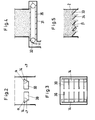
- FIGS. 2 and 3 show details of the current-carrying upper electrode 14.
- the electrode 14 consists of two opposite, at an angle ⁇ to the horizontal inclined, electrically conductive plates. From these inclined electrode plates 14 in turn, rake-like, also plate-shaped tongues 30 extend parallel to each other and vertically, i.e. aligned in the direction of flow of the material, on the one hand the Not unnecessarily hinder material flow, but on the other hand also a large surface for the to provide electrical contact with the electrically conductive bulk material.
- This arithmetic attached plates 30 also serve to even out the material flow and can for this purpose be even longer and be offset so that they partially in opposite spaces between the computing plates 30 of an opposite one Engage the electrode plate 14 a little.
- the electrode 14 as a ring electrode in the form of the shell of a truncated pyramid or is designed in the form of a funnel and can then instead of the calculating plates 30
- cross between opposite sides or diagonally through the Funnel-extending plates are provided, which on the one hand have a large current transfer area provide in the material, on the other hand to even out the material flow contribute so that the material does not go down faster, for example in the center of the shaft flows than in the more distant areas or vice versa.
- the equalization of the Material flow is also essentially determined by the way the material is pulled off at the lower end of the shaft determines the material of the entire shaft cross section should subtract as evenly as possible.
- FIG. 1 shows an embodiment with a scraper conveyor.
- the housing 31 of this Scraper conveyor is connected to the earth line.
- the scraper conveyor can be used in the usual way Chain belt, which extends over the entire width of the furnace shaft, be formed.
- the chain belt 35 is provided with a continuously adjustable drive 32, not shown here provided to a constant dwell time according to the mass flow to guarantee.
- a lamella floor is shown in FIG. Of the Lamella bottom forms the direct lower end of the shaft-shaped furnace space.
- the individual slats 34 are angularly or individually angled about their respective axes 33 adjustable. Depending on the opening width of the angle ⁇ , more or less heated bulk material flows due to the free cross sections between the slats.
- the actual organ of discharge is namely the individual lamellae are electrically connected to the earth and thus form the negative Pole or neutral conductor of the circuit.
- the slats On the representation of a common angle adjustment device the slats have been omitted in FIG. 5.
- FIG. 6 shows the arrangement of the heating device in an overall system.
- the bulk material to be heated is stored in 36, it can be coke, graphite, coal and also from mixtures of electrically conductive and electrically non-conductive bulk materials act.
- conveyor belt scales which measure the mass flow gravimetrically, drawn.
- the bulk material discharged from silos 35 and 36 passes through the Dosing device 11 in the furnace chamber 1 and leaves as heated bulk material with the help of Trigger device 9 the heating system. It then arrives in a processing machine 42, in which further components such as binders or the like are added can.
- the temperature measuring device 40 e.g. a radiation pyrometer, used for temperature monitoring, temperature deviations that could have occurred on the route, the Notify controller 43.
- the mass should be on the way to processing the machine 42 have lost in temperature, so a higher energy input in the bulk material is triggered, e.g. by increasing the current, but possibly also by Increase the dwell time.
- the control transformer 39 which in the case of heating with DC current combined with a rectifier ensures in conjunction with a current regulator 41 for the necessary energy input depending on the measured throughput Conveyor belt scale 37 and 38, the temperatures at the entry, measured with the temperature measuring device 43, and at the discharge, measured with the temperature measuring device 40, into the Calculation of the service entry.
- FIG. 7 shows a variant of the invention, in which the shaft in the lower section is gradually expanded. Electrodes are not shown in this figure, but can be have a similar arrangement and structure to that already in connection with FIG. 1 has been described.
- the material flows from top to bottom and forms on the step-shaped Transition 40, at which the container suddenly turns around from the perspective of the bulk material extends a horizontal step, a cavity 48. Since the bulk material consists of individual, granular elements and does not behave like a liquid, it also forms under the Pressure of the material slipping out of the tapered part of the container is still one certain cone, even if it may be smaller than that of a freely poured one Material.
- installations 42, 43 can also be seen in cross section, which likewise Define gas plenums and which if necessary in addition to the step-shaped ones Extensions 40 are provided, but on the other hand also with shafts with essentially constant cross-section such a step-like transition with respect to the function as Can replace gas collection space.
- the internals 42, 43 are z.
- the internals 42, 43 are convex from one side and formed concave from the other side and arranged in the shaft 1 so that it Bulk material that sinks from top to bottom should face its convex side.
- the terms “convex” and “concave” do not only refer to cross sections uniform or changing curvature, but also include, for example the triangular or roof shape of the element 42, a rectangular U-shape etc. From the The internals 42 and 43 do not necessarily have to be concave on the underside because, due to the bulk cone that forms at the bottom of the internals 42, 43 would also form a cavity 48 with respect to a horizontal lower surface anyway. The If possible, the upper convex side should always be designed so that none Bulk accumulates on it, but the material is only passed around the installation element becomes.
- Figure 8 shows the storage of such internals in opposite chess walls.
- the shaft walls in the left part are shown in section and show in particular a substantially rectangular recess 45 into which one end of the Elements 42 or 43 engages, the elements 42, 43 being longer than the clear distance between the opposite walls 2, but shorter than the clear distance between the recessed walls of the opposite recesses 45 so that they fit into this Cutouts can be used.
- the internals 42, 43 then lie with the lower one Edge of their two ends on the lower edge of the recess 45, the walls 2 of the Shaft in this area each have a bore 45a that connects to the gas collecting space 48 is aligned or connected, which is formed by the internals 42, 43.
- To the Through opening 45a can be connected to a suction nozzle or a suction line 46.
- FIG. 9 shows a further variant of a shaft, in which gas collecting spaces for removal of gas being formed are provided.
- gas collecting spaces for removal of gas being formed are provided.
- connections 56 can be made at through openings in the region of the Gas collecting spaces 54 can be provided in order to discharge or suck off the gas that forms.
- the sockets 56 and through openings, as well as the openings 45a or the Stub 41 in the embodiment according to FIG. 7 can, however, also advantageously be used for an additional material supply can be used.
- Degassing can also lead to a Change in the specific electrical resistance of the material come so that under Under certain circumstances, the supply of preferably gaseous or liquid, but also powdery or granular aggregate, which the desired electrical properties of the restores degassing bulk goods, can prove to be very useful.
- the internals can consist of electrically insulating material or with such Material, but there are also applications in which metallic or electrically conductive internals are preferred, which either for better power distribution care in the transverse direction or are connected as additional electrodes.
- the number and density of the gas collection spaces or internals to be provided can be in Flow direction of the bulk material varies and should be larger, especially where the degassing is particularly strong, e.g. rather in the lower area not far from the discharge of the Materials. Ultimately, however, the arrangement of the gas collecting spaces is also a question of processed material, the amperage used and the volatility of the material bound gases.
- the almost inevitable humidity of the electrically conductive heating Bulk material leads to steam development during the heating process.
- the steam development is particularly noteworthy when the bulk material is brought to temperatures above 100 ° C becomes.
- the resulting steam not only changes the resistance of the bulk material during the Warming, has a particularly negative effect on maintaining the tightest possible Residence time spectrum, so that a constant temperature of the heated bulk material on Discharge cannot be met with certainty.
- the resulting steam naturally tries to deposit and condense on cold bulk particles. That leads to it to a moist layer of bulk material between the bulk material cone at the product entry and the hotter zone begins within the bulk material. So it is inevitable to a certain increase in pressure as a result of the "upper seal" due to the moist bulk material. Vulture-like vapor breakthroughs both in the direction of product discharge and in the direction Product entry cannot be avoided. This will ensure even heating necessary narrow dwell time range significantly disturbed.
Landscapes
- Engineering & Computer Science (AREA)
- Mechanical Engineering (AREA)
- General Engineering & Computer Science (AREA)
- Furnace Details (AREA)
- Physical Or Chemical Processes And Apparatus (AREA)
- Heating, Cooling, Or Curing Plastics Or The Like In General (AREA)
Description
- Figur 1
- zeigt einen Längsschnitt durch die erfindungsgemäße Heizeinrichtung,
- Figur 2
- stellt einen Querschnitt durch die stromzuführende obere Elektrode dar,
- Figur 3
- zeigt eine Draufsicht auf die stromzuführende obere Elektrode,
- Figur 4
- zeigt eine Abzugsvorrichtung mit einem Kratzförderer,
- Figur 5
- zeigt einen verstellbaren Lamellenboden,
- Figur 6
- ist die schematische Darstellung einer Anlage mit der erfindungsgemäßen Heizeinrichtung,
- Figur 7
- eine Variante eines Schachtes mit einem stufenförmig erweiterten, unteren Behälterabschnitt sowie mit im Querschnitt erkennbaren Einbauten,
- Figur 8
- im linken Teilbild einen Schnitt durch zwei gegenüberliegende Behälterwände mit einem darin gelagerten Gassammeleinbau und im rechten Teilbild eine perspektivische Darstellung eines Gassammeleinbaues, und
- Figur 9
- einen Schacht mit von den Seitenwänden ausgehenden Blenden, die zusammen mit der Schachtwand Hohlräume bilden.
Bei einer Durchsatzmenge von ca. 30 t/Std. Petrolkoks mit einer Wasserfeuchte von nur 0,1 % werden stündlich 30 Liter Wasser verdampft. Dies entspricht einer Dampfmenge bei einer Dampftemperatur von 100°C von ca. 50 m3/h. Nachdem das Schüttgut während des Durchlaufes durch die Heizeinrichtung im allgemeinen auf Temperaturen im Bereich von 200°C aufgeheizt wird, nimmt dementsprechend der Dampf auch eine Temperatur von ca. 200°C an. Demzufolge ist die resultierende Dampfmenge noch deutlich größer.
Claims (29)
- Verfahren zum kontinuierlichen Eintrag von Wärme in elektrisch leitfähige Schüttgüter unter Ausnutzung deren elektrischen Widerstandes, in einem Ofenraum mit einer Einlauföffnung und einer Abzugsvorrichtung für den kontinuierlichen Durchsatz von Schüttgut, wobei während des Materialdurchlaufes elektrische Energie in das Material eingeleitet wird, dadurch gekennzeichnet, daß das Material zwischen der positiven und negativen Elektrode im wesentlichen parallel zur Stromrichtung geführt wird und daß die Abzugsvorrichtung mindestens als Teil der negativen Elektrode bzw. des Nulleiters verwendet wird.
- Verfahren nach Anspruch 1, wobei das Schüttgut in einem Schacht abwärts geleitet wird, dadurch gekennzeichnet, daß das erwärmte Material durch die am unteren Ende des Schachtes vorgesehene Abzugsvorrichtung (9) im wesentlichen gleichmäßig von dem gesamten Schachtquerschnitt abgezogen wird.
- Vorrichtung zum kontinuierlichen Eintrag von Wärme in elektrisch leitfähige Schüttgüter unter Ausnutzung von deren elektrischem Widerstand, mit einem Ofenraum (1) mit einer Einlauföffnung (15) und einer kontinuierlichen Abzugsvorrichtung (9) für das Schüttgut und mit mindestens einem Elektrodenpaar (14, 16, 19), über welches während des kontinuierlichen Materialdurchlaufes elektrische Energie in das Material eingeleitet wird, dadurch gekennzeichnet, daß sich die positiv gepolte Elektrode oder Phasenelektrode (14) in der Nähe der Einlauföffnung (15) befindet und die negativ gepolte Elektrode bzw. Nulleiterelektrode (16, 9) im Bereich der Abzugsvorrichtung (9) vorgesehen ist und die negativ gepolte Elektrode bzw. Nulleiterelektrode (16, 9) und die Abzugsvorrichtung (9) geerdet sind.
- Vorrichtung nach Anspruch 3, dadurch gekennzeichnet, daß die innere Gehäusewand der Abzugsvorrichtung (9) geerdet ist und mindestens als Teil der negativen Elektrode bzw. des Nulleiters dient.
- Vorrichtung nach Anspruch 3 oder 4, dadurch gekennzeichnet, daß neben der Wand der Abzugseinrichtung mindestens eine weitere zu- bzw. abschaltbare negative Elektrode bzw. Nulleiterelektrode (16, 16a) in der Nähe der Abzugsvorrichtung (9) vorgesehen ist.
- Vorrichtung nach einem der Ansprüche 3 bis 5, dadurch gekennzeichnet, daß zwischen der Abzugsvorrichtung (9) und der positiven Elektrode bzw. Phasenelektrode (14) mehrere negative Elektroden bzw. Nulleiterelektroden (16, 16a) in verschiedenen Abständen zur Abzugsvorrichtung (9) angeordnet sind.
- Vorrichtung nach einem der Ansprüche 3 bis 6, dadurch gekennzeichnet, daß eine neben der Abzugsvorrichtung (9) vorhandene, negative Elektrode (16, 16a) in ihrem Abstand zu der Abzugsvorrichtung und/oder der positiven Elektrode (14) einstellbar ist.
- Vorrichtung nach einem der Ansprüche 3 bis 7, dadurch gekennzeichnet, daß oberhalb der positiven Elektrode (14) im schüttgutfreien Raum eine geerdete Schutzelektrode (18) vorgesehen ist.
- Vorrichtung nach Anspruch 8, dadurch gekennzeichnet, daß die Schutzelektrode (18) oberhalb des Schüttgutes über eine Strommeßeinrichtung (20) mit Masse verbunden ist.
- Vorrichtung nach Anspruch 8 oder 9, dadurch gekennzeichnet, daß eine Spannungsmeßeinrichtung vorgesehen ist für die Messung eines Spannungsabfalls entlang der Verbindung zwischen Schutzelektrode (18) und Masse.
- Vorrichtung nach einem der Ansprüche 3 bis 10, dadurch gekennzeichnet, daß unmittelbar oberhalb der positiven Elektrode (14) und innerhalb eines normalen Schüttgutstandes eine Überwachungselektrode (21) über einen Widerstand (R1) mit Masse verbunden ist.
- Vorrichtung nach einem der Ansprüche 3 bis 11, dadurch gekennzeichnet, daß die Abzugsvorrichtung (9) aus einem mit Masse verbundenen Gehäuse und einer oder mehreren angetriebenen Transportschnecken (8) besteht.
- Vorrichtung nach einem der Ansprüche 3 bis 11, dadurch gekennzeichnet, daß als Abzugsvorrichtung (9) ein mit Masse verbundenes Gehäuse mit einem darin befindlichen Austragskratzersystem (31) mit regelbarem Antrieb (32) vorgesehen ist.
- Vorrichtung nach einem der Ansprüche 3 bis 13, dadurch gekennzeichnet, daß als Abzugsvorrichtung (9) ein sogenannter Lamellenboden vorgesehen und mit Masse verbunden ist und daß der Öffnungswinkel (B) der Lamellen (4) einstellbar ist.
- Vorrichtung nach einem der Ansprüche 3 bis 14, dadurch gekennzeichnet, daß die positive Elektrode (14) trichterförmig angeordnete Begrenzungswände (30) aufweist.
- Vorrichtung nach Anspruch 15, dadurch gekennzeichnet, daß Zungen (30) sich von gegenüberliegenden Wänden der positiven Elektrode (14) aus parallel zueinander und mit ihrer Ebene in Fließrichtung des Materiales ausgerichtet angeordnet sind.
- Vorrichtung nach einem der Ansprüche 3 bis 16, dadurch gekennzeichnet, daß zumindest die als Elektrode wirkenden Teile der Abzugsvorrichtung (9) und/oder die Abzugsvorrichtung (9) als Ganzes als leicht von dem Ofen demontierbare Austauschtelle vorgesehen sind.
- Vorrichtung nach einem der Ansprüche 3 bis 17, dadurch gekennzeichnet, daß der Schacht bzw. Ofenraum einen im wesentlichen konstantem Querschnitt aufweist.
- Vorrichtung nach einem der Ansprüche 3 bis 17, dadurch gekennzeichnet, daß der Ofenraum- bzw. Schachtquerschnitt absatzweise in einer oder mehreren Teilstufen (40) quer zur Materialflußrichtung erweitert ist.
- Vorrichtung nach Anspruch 19, dadurch gekennzeichnet, daß sich die Wand des Schachtabschnittes mit dem jeweils kleineren Querschnitt in den Schachtabschnitt (2a) mit dem jeweils größeren Querschnitt teilweise hineinerstreckt.
- Vorrichtung nach Anspruch 19 oder 20, dadurch gekennzeichnet, daß im Bereich der stufenförmigen Erweiterung verschließbare Entlüftungsöffnungen (41) angeordnet sind.
- Vorrichtung nach einem der Ansprüche 3 bis 21, dadurch gekennzeichnet, daß hohlraumbildende Einbauten (43, 50, 51, 52) im Inneren des Schachtes (1) eingebaut sind.
- Vorrichtung nach Anspruch 22, dadurch gekennzeichnet, daß sich die hohlraumbildenden Einbauten quer und vorzugsweise genau senkrecht zur Materialflußrichtung durch den Innenraum des Schachtes (1) erstrecken.
- Vorrichtung nach Anspruch 22 oder 23, dadurch gekennzeichnet, daß die hohlraumbildenden Einbauten (50, 51, 52) mit der Schachtwand einen gemeinsamen Hohlraum bilden.
- Vorrichtung nach einem der Ansprüche 22 bis 24, dadurch gekennzeichnet, daß die Einbauten (42, 43) in Aussparungen (45) in gegenüberliegenden Wänden des Schachtes gelagert sind.
- Vorrichtung nach Anspruch 25, dadurch gekennzeichnet, daß in der Schachtwand (2) vorzugsweise verschließbare Durchgangsöffnungen (45a) in Flucht mit den hohlraumbildenden Einbauten (42, 43) vorgesehen sind.
- Vorrichtung nach einem der Ansprüche 22 bis 26, dadurch gekennzeichnet, daß die Einbauten aus einem isolierenden Material bestehen oder mit einem isolierenden Material beschichtet sind.
- Vorrichtung nach einem der Ansprüche 22 bis 26, dadurch gekennzeichnet, daß die hohlraumbildenden Einbauten als stromleitende Elektroden ausgebildet sind.
- Vorrichtung nach einem der Ansprüche 19 bis 28, dadurch gekennzeichnet, daß die durch Schachterweiterungen oder Einbauten gebildeten Hohlräume und/oder die mit diesen in Verbindung stehenden Durchgangsöffnungen an eine Absaugleitung angeschlossen sind.
Applications Claiming Priority (2)
| Application Number | Priority Date | Filing Date | Title |
|---|---|---|---|
| DE4304217 | 1993-02-12 | ||
| DE4304217A DE4304217A1 (de) | 1993-02-12 | 1993-02-12 | Verfahren und Vorrichtung zum kontinuierlichen Eintrag von Wärme in elektrisch leitfähige Schüttgüter |
Publications (2)
| Publication Number | Publication Date |
|---|---|
| EP0610704A1 EP0610704A1 (de) | 1994-08-17 |
| EP0610704B1 true EP0610704B1 (de) | 1998-04-01 |
Family
ID=6480302
Family Applications (1)
| Application Number | Title | Priority Date | Filing Date |
|---|---|---|---|
| EP94100930A Expired - Lifetime EP0610704B1 (de) | 1993-02-12 | 1994-01-23 | Verfahren und Vorrichtung zum kontinuierlichen Eintrag von Wärme in elektrisch leitfähige Schüttgüter |
Country Status (8)
| Country | Link |
|---|---|
| US (1) | US5694413A (de) |
| EP (1) | EP0610704B1 (de) |
| CN (1) | CN1065407C (de) |
| AU (1) | AU670985B2 (de) |
| CA (1) | CA2115503C (de) |
| DE (2) | DE4304217A1 (de) |
| NO (1) | NO306010B1 (de) |
| RU (1) | RU2127498C1 (de) |
Families Citing this family (9)
| Publication number | Priority date | Publication date | Assignee | Title |
|---|---|---|---|---|
| US6038247A (en) * | 1997-06-05 | 2000-03-14 | Ishikawajima-Harima Jukogyo Kabushiki Kaisha | Graphitizing electric furnace |
| US5946342A (en) * | 1998-09-04 | 1999-08-31 | Koslow Technologies Corp. | Process and apparatus for the production of activated carbon |
| US20050048661A1 (en) * | 2003-08-25 | 2005-03-03 | Droit Jimmy L. | Methods and apparatus for analyzing materials |
| DE102004020790A1 (de) * | 2004-04-28 | 2005-11-24 | Maschinenfabrik Gustav Eirich Gmbh & Co. Kg | Verfahren und Vorrichtung zum kontinuierlichen geregelten Austrag von Feststoffen |
| FI7104U1 (fi) * | 2006-01-25 | 2006-06-08 | Jorma Antti Kalevi Kivimaeki | Hienoaineen erotin |
| DE102011110960B4 (de) * | 2011-08-24 | 2014-07-17 | Schenck Process Gmbh | Selbstkalibrierende Dosiervorrichtung |
| DE102013220501A1 (de) * | 2013-10-11 | 2015-04-16 | Technische Universität Bergakademie Freiberg | Verfahren und Vorrichtung zur Kohle-Pyrolyse |
| DE102021111916A1 (de) * | 2021-05-07 | 2022-11-10 | Fraunhofer-Gesellschaft zur Förderung der angewandten Forschung eingetragener Verein | Verfahren zur direkten widerstandsbeheizung oder analyse einer füllung in einem verfahrenstechnischen apparat |
| CN117490364B (zh) * | 2024-01-03 | 2024-03-12 | 吉蒙炭素有限责任公司 | 一种基于原料导电的干料加热装置及加热方法 |
Family Cites Families (20)
| Publication number | Priority date | Publication date | Assignee | Title |
|---|---|---|---|---|
| US757634A (en) * | 1903-04-30 | 1904-04-19 | Union Carbide Corp | Electric-resistance furnace. |
| US779844A (en) * | 1903-10-27 | 1905-01-10 | William Steuart | Electric furnace. |
| US815016A (en) * | 1905-06-14 | 1906-03-13 | Electro Metallurg Francaise Soc | Process of smelting iron ore. |
| US1430971A (en) * | 1922-04-14 | 1922-10-03 | Fornander Edvin | Method of and means for reducing ores in electric blast furnaces |
| DE537229C (de) * | 1927-07-19 | 1931-10-31 | Thaddeus Francis Baily | Elektrischer Schachtofen |
| DE1133513B (de) * | 1959-04-18 | 1962-07-19 | Voest Ag | Elektrischer Schmelzofen fuer Hochofenschlacke od. dgl. |
| DE1571443B1 (de) * | 1964-10-10 | 1975-06-05 | Elkem Spigerverket As | Elektrischer Ofen zur direkten Widerstandserhitzung von kohlenstoffhaltigen Rohstoffen fuer die Elektrodenherstellung von Schmelzoefen |
| US4261857A (en) * | 1974-05-09 | 1981-04-14 | Kyoritsu Yuki Kogyo Kenkyusho | Method and apparatus for regenerating used active carbon |
| FR2384412A1 (fr) * | 1977-03-18 | 1978-10-13 | France Syndicat Fab Sucre | Procede et dispositif de chauffage d'un liquide notamment un liquide visqueux, en particulier masse cuite de sucrerie |
| FR2410235A1 (fr) * | 1977-11-25 | 1979-06-22 | Fusion Volatilisation | Nouveau four electrique a haut rendement pour la calcination des matieres carbonees |
| US4192962A (en) * | 1978-05-19 | 1980-03-11 | Kabushiki Kaisha Kyoritsu Yuki Kogyo Kenkyusho | Method and apparatus for regenerating used activated carbon |
| JPS56500691A (de) * | 1979-06-08 | 1981-05-21 | ||
| DE2954379C2 (de) * | 1979-12-04 | 1987-12-03 | Vereinigte Aluminium-Werke Ag, 1000 Berlin Und 5300 Bonn, De | |
| US4405433A (en) * | 1981-04-06 | 1983-09-20 | Kaiser Aluminum & Chemical Corporation | Aluminum reduction cell electrode |
| DE3214472A1 (de) * | 1982-04-20 | 1983-10-27 | Hubert Eirich | Vorrichtung zum erhitzen von elektrisch leitfaehigen schuettguetern |
| DE3341748A1 (de) * | 1983-11-18 | 1985-05-30 | Kraftwerk Union AG, 4330 Mülheim | Verfahren und ofen zur beseitigung radioaktiver abfaelle |
| DE3611687A1 (de) * | 1986-04-08 | 1987-10-15 | Hansa Metallwerke Ag | Verfahren zur herstellung von kunststoff-formkoerpern |
| JPS6388037A (ja) * | 1986-04-29 | 1988-04-19 | カ−ボン・アクテイベ−タ−ス(プロライアタリ−)リミテツド | 粒子状物質の処理装置 |
| SU1706063A1 (ru) * | 1989-12-27 | 1992-01-15 | .Стругацкий, А.Н.Стругацкий, В.А.Смирнов и К.И.Асанов | Электродный проточный водонагреватель |
| AU643611B2 (en) * | 1991-04-10 | 1993-11-18 | Mintek | Direct resistance heating electrical furnace assembly and method of operating same |
-
1993
- 1993-02-12 DE DE4304217A patent/DE4304217A1/de not_active Withdrawn
-
1994
- 1994-01-23 EP EP94100930A patent/EP0610704B1/de not_active Expired - Lifetime
- 1994-01-23 DE DE59405552T patent/DE59405552D1/de not_active Expired - Lifetime
- 1994-02-08 CN CN94101753A patent/CN1065407C/zh not_active Expired - Fee Related
- 1994-02-09 NO NO940432A patent/NO306010B1/no not_active IP Right Cessation
- 1994-02-11 RU RU94004984A patent/RU2127498C1/ru not_active IP Right Cessation
- 1994-02-11 CA CA002115503A patent/CA2115503C/en not_active Expired - Fee Related
- 1994-02-11 AU AU55104/94A patent/AU670985B2/en not_active Ceased
-
1996
- 1996-06-02 US US08/676,102 patent/US5694413A/en not_active Expired - Lifetime
Also Published As
| Publication number | Publication date |
|---|---|
| CN1065407C (zh) | 2001-05-02 |
| AU670985B2 (en) | 1996-08-08 |
| NO940432L (no) | 1994-08-15 |
| DE59405552D1 (de) | 1998-05-07 |
| CN1095545A (zh) | 1994-11-23 |
| NO940432D0 (no) | 1994-02-09 |
| RU2127498C1 (ru) | 1999-03-10 |
| NO306010B1 (no) | 1999-08-30 |
| CA2115503A1 (en) | 1994-08-13 |
| CA2115503C (en) | 2001-04-17 |
| EP0610704A1 (de) | 1994-08-17 |
| AU5510494A (en) | 1994-08-18 |
| DE4304217A1 (de) | 1994-08-18 |
| US5694413A (en) | 1997-12-02 |
Similar Documents
| Publication | Publication Date | Title |
|---|---|---|
| EP0092036B1 (de) | Vorrichtung zum Erhitzen von elektrisch leitfähigen Schüttgütern | |
| DE68911136T2 (de) | Elektrischer apparat. | |
| DE2135485B2 (de) | Vorrichtung zum zufuehren von aluminiumoxid | |
| EP0610704A1 (de) | Verfahren und Vorrichtung zum kontinuierlichen Eintrag von Wärme in elektrisch leitfähige Schüttgüter | |
| EP0074076B1 (de) | Silo für insbesondere schwerfliessendes Schüttgut | |
| EP2470848B1 (de) | Aufgabeschurre für sintermaterial | |
| EP3530630B1 (de) | Vorrichtung zur bestimmung der schüttdichte | |
| DE4015785C2 (de) | ||
| DE4027693A1 (de) | Verfahren und vorrichtung zum trennen von partikeln in einem elektrostatischen ausfaellapparat | |
| DE102012006584A1 (de) | Behälterdeckel | |
| CH642869A5 (de) | Verfahren zum abscheiden von feinverteilten feststoffen aus einem gasstrom und apparat zur durchfuehrung des verfahrens. | |
| EP1671518B1 (de) | Aggregat f r konduktiv beheizbares schmelzen | |
| DD233411A5 (de) | Schachtanordnung fuer thermisch und/oder stoffuebertragungsvorgaenge zwischen einem gas und einem schuettvorgang | |
| DE2809570A1 (de) | Zerkleinerungsanlage fuer rostkuehler | |
| DE1751164A1 (de) | Vorrichtung zur kontinuierlichen thermischen Behandlung von schuettfaehigem koernigem Gut | |
| DE102010008412A1 (de) | Vorrichtung zur Erwärmung von Flüssigkeiten | |
| WO1981002302A1 (fr) | Dispositif de vidange pour une installation de pyrolyse | |
| DE2809927A1 (de) | Schachtkuehler | |
| DE19722906A1 (de) | Verfahren zum Blähen granulierten Materials durch thermische Behandlung und Vorrichtung zur Durchführung des Verfahrens | |
| DE3212975C2 (de) | ||
| DE3226591C2 (de) | Trocknungsturm für pulverförmige Stoffe | |
| EP0311638B1 (de) | Vorrichtung zur kokstrockenkühlung | |
| DE3805551A1 (de) | Verfahren und vorrichtung zur feuchtigkeitssteuerung eines schuettgutes in einem silo | |
| DE4211663C2 (de) | Glühstabverschweler für Getreidestroh | |
| EP3258199B1 (de) | Vorrichtung zum trocknen von schüttgut |
Legal Events
| Date | Code | Title | Description |
|---|---|---|---|
| PUAI | Public reference made under article 153(3) epc to a published international application that has entered the european phase |
Free format text: ORIGINAL CODE: 0009012 |
|
| AK | Designated contracting states |
Kind code of ref document: A1 Designated state(s): CH DE FR GB LI NL |
|
| 17P | Request for examination filed |
Effective date: 19950201 |
|
| GRAG | Despatch of communication of intention to grant |
Free format text: ORIGINAL CODE: EPIDOS AGRA |
|
| 17Q | First examination report despatched |
Effective date: 19970307 |
|
| GRAG | Despatch of communication of intention to grant |
Free format text: ORIGINAL CODE: EPIDOS AGRA |
|
| GRAH | Despatch of communication of intention to grant a patent |
Free format text: ORIGINAL CODE: EPIDOS IGRA |
|
| GRAH | Despatch of communication of intention to grant a patent |
Free format text: ORIGINAL CODE: EPIDOS IGRA |
|
| GRAA | (expected) grant |
Free format text: ORIGINAL CODE: 0009210 |
|
| AK | Designated contracting states |
Kind code of ref document: B1 Designated state(s): CH DE FR GB LI NL |
|
| REG | Reference to a national code |
Ref country code: CH Ref legal event code: NV Representative=s name: ISLER & PEDRAZZINI AG Ref country code: CH Ref legal event code: EP |
|
| GBT | Gb: translation of ep patent filed (gb section 77(6)(a)/1977) |
Effective date: 19980402 |
|
| REF | Corresponds to: |
Ref document number: 59405552 Country of ref document: DE Date of ref document: 19980507 |
|
| ET | Fr: translation filed | ||
| PLBE | No opposition filed within time limit |
Free format text: ORIGINAL CODE: 0009261 |
|
| STAA | Information on the status of an ep patent application or granted ep patent |
Free format text: STATUS: NO OPPOSITION FILED WITHIN TIME LIMIT |
|
| 26N | No opposition filed | ||
| REG | Reference to a national code |
Ref country code: GB Ref legal event code: IF02 |
|
| REG | Reference to a national code |
Ref country code: CH Ref legal event code: PCAR Free format text: ISLER & PEDRAZZINI AG;POSTFACH 1772;8027 ZUERICH (CH) |
|
| PGFP | Annual fee paid to national office [announced via postgrant information from national office to epo] |
Ref country code: CH Payment date: 20100125 Year of fee payment: 17 |
|
| PGFP | Annual fee paid to national office [announced via postgrant information from national office to epo] |
Ref country code: FR Payment date: 20100223 Year of fee payment: 17 |
|
| PGFP | Annual fee paid to national office [announced via postgrant information from national office to epo] |
Ref country code: GB Payment date: 20100121 Year of fee payment: 17 |
|
| PGFP | Annual fee paid to national office [announced via postgrant information from national office to epo] |
Ref country code: NL Payment date: 20100118 Year of fee payment: 17 Ref country code: DE Payment date: 20100323 Year of fee payment: 17 |
|
| REG | Reference to a national code |
Ref country code: NL Ref legal event code: V1 Effective date: 20110801 |
|
| REG | Reference to a national code |
Ref country code: CH Ref legal event code: PL |
|
| GBPC | Gb: european patent ceased through non-payment of renewal fee |
Effective date: 20110123 |
|
| REG | Reference to a national code |
Ref country code: FR Ref legal event code: ST Effective date: 20110930 |
|
| PG25 | Lapsed in a contracting state [announced via postgrant information from national office to epo] |
Ref country code: CH Free format text: LAPSE BECAUSE OF NON-PAYMENT OF DUE FEES Effective date: 20110131 Ref country code: LI Free format text: LAPSE BECAUSE OF NON-PAYMENT OF DUE FEES Effective date: 20110131 Ref country code: FR Free format text: LAPSE BECAUSE OF NON-PAYMENT OF DUE FEES Effective date: 20110131 |
|
| PG25 | Lapsed in a contracting state [announced via postgrant information from national office to epo] |
Ref country code: GB Free format text: LAPSE BECAUSE OF NON-PAYMENT OF DUE FEES Effective date: 20110123 |
|
| REG | Reference to a national code |
Ref country code: DE Ref legal event code: R119 Ref document number: 59405552 Country of ref document: DE Effective date: 20110802 |
|
| PG25 | Lapsed in a contracting state [announced via postgrant information from national office to epo] |
Ref country code: NL Free format text: LAPSE BECAUSE OF NON-PAYMENT OF DUE FEES Effective date: 20110801 |
|
| PG25 | Lapsed in a contracting state [announced via postgrant information from national office to epo] |
Ref country code: DE Free format text: LAPSE BECAUSE OF NON-PAYMENT OF DUE FEES Effective date: 20110802 |