EP0608863B1 - Connecteur blindé - Google Patents
Connecteur blindé Download PDFInfo
- Publication number
- EP0608863B1 EP0608863B1 EP94101133A EP94101133A EP0608863B1 EP 0608863 B1 EP0608863 B1 EP 0608863B1 EP 94101133 A EP94101133 A EP 94101133A EP 94101133 A EP94101133 A EP 94101133A EP 0608863 B1 EP0608863 B1 EP 0608863B1
- Authority
- EP
- European Patent Office
- Prior art keywords
- retaining
- shield
- connector housing
- metal terminal
- resilient
- Prior art date
- Legal status (The legal status is an assumption and is not a legal conclusion. Google has not performed a legal analysis and makes no representation as to the accuracy of the status listed.)
- Expired - Lifetime
Links
Images


Classifications
-
- H—ELECTRICITY
- H01—ELECTRIC ELEMENTS
- H01R—ELECTRICALLY-CONDUCTIVE CONNECTIONS; STRUCTURAL ASSOCIATIONS OF A PLURALITY OF MUTUALLY-INSULATED ELECTRICAL CONNECTING ELEMENTS; COUPLING DEVICES; CURRENT COLLECTORS
- H01R13/00—Details of coupling devices of the kinds covered by groups H01R12/70 or H01R24/00 - H01R33/00
- H01R13/40—Securing contact members in or to a base or case; Insulating of contact members
- H01R13/42—Securing in a demountable manner
- H01R13/436—Securing a plurality of contact members by one locking piece or operation
- H01R13/4361—Insertion of locking piece perpendicular to direction of contact insertion
-
- H—ELECTRICITY
- H01—ELECTRIC ELEMENTS
- H01R—ELECTRICALLY-CONDUCTIVE CONNECTIONS; STRUCTURAL ASSOCIATIONS OF A PLURALITY OF MUTUALLY-INSULATED ELECTRICAL CONNECTING ELEMENTS; COUPLING DEVICES; CURRENT COLLECTORS
- H01R13/00—Details of coupling devices of the kinds covered by groups H01R12/70 or H01R24/00 - H01R33/00
- H01R13/648—Protective earth or shield arrangements on coupling devices, e.g. anti-static shielding
- H01R13/658—High frequency shielding arrangements, e.g. against EMI [Electro-Magnetic Interference] or EMP [Electro-Magnetic Pulse]
- H01R13/6581—Shield structure
- H01R13/6582—Shield structure with resilient means for engaging mating connector
-
- H—ELECTRICITY
- H01—ELECTRIC ELEMENTS
- H01R—ELECTRICALLY-CONDUCTIVE CONNECTIONS; STRUCTURAL ASSOCIATIONS OF A PLURALITY OF MUTUALLY-INSULATED ELECTRICAL CONNECTING ELEMENTS; COUPLING DEVICES; CURRENT COLLECTORS
- H01R13/00—Details of coupling devices of the kinds covered by groups H01R12/70 or H01R24/00 - H01R33/00
- H01R13/648—Protective earth or shield arrangements on coupling devices, e.g. anti-static shielding
- H01R13/658—High frequency shielding arrangements, e.g. against EMI [Electro-Magnetic Interference] or EMP [Electro-Magnetic Pulse]
- H01R13/6591—Specific features or arrangements of connection of shield to conductive members
- H01R13/6592—Specific features or arrangements of connection of shield to conductive members the conductive member being a shielded cable
Definitions
- This invention relates to a shield connector of the type in which a shield cover is fitted on a connector housing and more particularly to a shield cover including a double-lock structure for preventing withdrawal of the terminal and structure enabling detection of an incomplete insertion.
- One known shield connector of this type comprises an insulative connector housing having terminal receiving chambers into which metal terminals connected respectively to core wires of a shield wire are respectively inserted from rear ends of these chambers.
- the shield connector also includes an electrically-conductive shield cover fitted on the connector housing and electrically connected to a shield conductor of the shield wire when the shield cover is fitted on the connector housing.
- a first construction is a so-called single lock construction, in which resilient retaining pawls are formed on the connector housing or the metal terminals, and when the metal terminal is inserted into a predetermined position within the terminal receiving chamber of the connector housing, the resilient pawl performs its retaining function.
- the metal terminal is retained only at one portion, and therefore the withdrawal prevention force is inferior.
- the resilient retaining pawl may exhibit a weak retaining force to hold the metal terminal in a provisionally-retained condition. In such a condition, the operator is liable to misunderstand that complete insertion has been made, resulting in a problem that a defect such as withdrawal of the metal terminal arises after the connection of the connector.
- a second construction called a double lock construction has been proposed.
- a retainer for insertion into the connector housing.
- the retainer is first inserted into a provisionally-retained position, and the metal terminal is inserted into the connector housing from a rear end thereof, so that the resilient retaining pawl retains the metal terminal against withdrawal. Thereafter, the retainer is farther pushed from the provisionally-retained position, so that a retaining projection formed on the retainer is engaged with the metal terminal, thereby completely holding the metal terminal against movement in its withdrawing direction.
- the metal terminal is retained at two portions by the resilient retaining pawl of the connector housing and the retaining projection of the retainer, and therefore a strong withdrawal prevention force can be obtained. If the metal terminal is not inserted into the proper position within the terminal receiving chamber, the retainer cannot be further pushed from the provisionally-retained position, and therefore the incompletely inserted condition can be detected, thus achieving an effect of preventing a defect (i.e., terminal withdrawal) from arising.
- the separate part that is, the retainer
- the shield connector is of the type including, in addition to the metal terminals and the connector housing, a shield cover for fitting on the connector housing, there is encountered a drawback that the number of parts is considerably increased.
- the present invention has been made under the above circumstances, and therefore an object of the invention is to provide a shield connector that has a metal terminal withdrawal prevention function and an incomplete metal terminal insertion-detecting function, which functions are equivalent to those of a double lock-type connector, without increasing the number of component parts.
- a first retaining device that is engaged with a metal terminal inserted into a predetermined position within a terminal receiving chamber of a connector housing, thereby preventing the movement of the metal terminal in a withdrawing direction.
- a second retaining device is engageable with the metal terminal when the metal terminal reaches the predetermined position and prevents the movement of the metal terminal in the withdrawing direction when the second retaining device engages the metal terminal.
- the second retaining device engages the metal terminal when the shield cover is fitted on the connector housing.
- the second retaining device may include a resilient retaining portion resiliently, deformably mounted on the connector housing, wherein when the shield cover is fitted on the connector housing, the resilient retaining portion is deformed by the shield cover into engagement with the metal terminal inserted into the predetermined position.
- the second retaining device may further include a retaining portion mounted on the shield cover, wherein when the shield cover is fitted on the connector housing, the retaining portion is brought into engagement with the metal terminal inserted into the predetermined position.
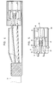
- the construction comprises a tubular insulative cover 1, a shield wire 10, an insulative connector housing 30, and an electrically-conductive shield cover 40.
- the connector housing 30 is attached to a front end of the shield wire 10 as shown in Fig. 2.
- the shield cover 40 is fitted on the connector housing 30, and the insulative cover 1 is fitted on the shield cover 40. This assembled condition is shown in Fig. 3.
- the shield wire 10 is of a conventional construction, and comprises a bundle, for example, of eight core wires 12, a mesh-like shield conductor 14 covering an outer periphery of the bundle through an insulative cover, and an insulative sheath 15 covering the shield conductor 14.
- a metal terminal 11 is fixedly secured to a front end of each core wire 12.
- the metal terminal 11 is an elongate, tubular male terminal, and has at its rear portion an insulation barrel 16 compressively clamped to a cover of the core wire 12, a wire barrel 17 compressively clamped to a conductor of the core wire 12, and a contact portion 18 at its front end portion.
- the metal terminal 11 has a resilient retaining piece 19 that is formed by stamping and raising part of the metal terminal, the retaining piece 19 extending obliquely rearwardly.
- a retaining portion 21 is formed on that portion of the metal terminal 11 facing away from the resilient retaining piece 19 and extends perpendicular to the direction of the length of the metal terminal 11, the retaining portion 21 facing rearwardly.
- An outer surface of retaining portion 21 extending forwardly from the retaining portion 21 serves as an engagement portion 22 extending parallel to the direction of the length of the metal terminal 11.
- the connector housing 30 is of a tubular shape having a square cross-section and has eight terminal receiving chambers 31 for respectively receiving the metal terminals 11 of the shield wire 10.
- An upper row of four juxtaposed chambers 31 and a lower row of four juxtaposed chambers 31 are arranged in pairs.
- a retaining projection 33 is provided in each terminal receiving chamber 31, projecting from a partition wall 32 dividing each pair of terminal receiving chambers 31 from each other. Retaining projection 33 cooperates with the resilient retaining piece 19 of the metal terminal 11 of the shield wire 10 to form a first retaining means 35.
- the connector housing 30 has four juxtaposed elongate resilient retaining portions (resilient retaining pawls) 36 provided at each of upper and lower walls that isolate the terminal receiving chambers 31 from the outer surface of the connector housing.
- Each of the resilient retaining pawls 36 extends rearwardly from a generally central portion of the upper or the lower wall and is bent at its distal end portion to project into the terminal receiving chamber 31.
- the resilient retaining pawls 36 are provided in corresponding relation to the terminal receiving chambers 31, respectively.
- the resilient retaining pawl 36 cooperates with the retaining portion 21 and the engagement portion 22 of the metal terminal 11 to form a second retaining means 37.
- a projection 38 is formed on an outer surface of the distal end of each resilient retaining pawl 36. Projection 38 projects beyond the upper or the lower surface of the connector housing 30, respectively when the resilient retaining pawl 36 is not resiliently deformed.
- a non-deformable portion 39, extending parallel to the resilient retaining pawls 36 is formed between any two adjacent ones of the row of four juxtaposed resilient retaining pawls 36. Thus, three non-deformable portions 39 are provided at each of the upper and lower walls.
- pawl 36 When the resilient retaining pawl 36 is in a free condition, that is, not resiliently deformed, pawl 36 is disposed out of a path of insertion of the metal terminal 11 into the terminal receiving chamber 31, and therefore, pawl 36 does not inhibit the insertion of the metal terminal.
- the resilient retaining pawl 36 When the resilient retaining pawl 36 is resiliently deformed to such an extent that the projection 38 on the outer surface of the distal end of pawl 36 does not project outwardly beyond the outer surface of the connector housing 30, the resilient retaining pawl 36 retainingly engages the retaining portion 21 of the metal terminal 11, inserted into the predetermined position within the terminal receiving chamber 31, from the rear side.
- the resilient retaining pawl 36 When the metal terminal 11 is not fully inserted into the predetermined position within the terminal receiving chamber 31, the resilient retaining pawl 36 is slightly resiliently deformed to engage the engagement portion 22 of the metal terminal 11, and is prevented from being further deformed resiliently. In this further deformation-prevented condition, the projection 38 on the outer surface of the distal end is projected beyond the outer surface of the connector housing 30.
- the shield cover 40 is formed by bending an electrically-conductive metal plate into a tubular shape.
- the shield cover 40 has a front end portion defining a fitting portion 41 for intimately fitting on the outer surface of the connector housing 30, a central portion defining an insertion portion 42 with an upwardly-openable lid 43, and a rear end portion defining a connection portion 44 for embracing the shield conductor 14 of the shield wire 10 to be electrically connected thereto.
- the lid 43 of the central portion of the shield cover 40 is opened, and the connector housing 30 is inserted into the insertion portion 42.
- the connector housing 30 is moved forwardly relative to the shield cover to be pushed into the fitting portion 41, and the connection portion 44 at the rear end portion is deformed to clamp the shield conductor 14.
- the shield cover 40 is attached to the shield wire 10 and the connector housing 30.
- the resilient retaining pawls 36 are inwardly urged and deformed resiliently.
- the projections 38 When the resilient retaining pawls 36 are inhibited from resilient deformation, with the projections 38 on their distal ends projected beyond the outer surface of the connector housing 30, the projections 38 abut against a rear edge of the fitting portion 41, so that the pushing of the connector housing 30 into the fitting portion 41 is prevented.
- the insulative cover 1 After attaching the shield cover 40, the insulative cover 1 is moved forwardly to cover the connector housing and the shield cover 40.
- the metal terminals 11 are first inserted into the terminal receiving chambers 31 of the connector housing 30, respectively. As each metal terminal 11 is inserted, the resilient retaining piece 19 of the metal terminal 11 constituting the first retaining means 35 abuts against the tip of the retaining projection 33. Simultaneously, when the metal terminal 11 is inserted into the predetermined position, the resilient retaining piece 19 of the metal terminal 11 is restored to be retained by the front face of the retaining projection 33, as shown in Fig. 5. As a result, the movement of the metal terminal 11 in a rearward direction, that is, in a withdrawing direction, is prevented.
- the distal end of the resilient retaining pawl 36 faces the engagement portion 22 of the metal terminal 11 when the shield wire 10 and the connector housing 30 are connected together.
- the projection 38 of the resilient retaining pawl 36 is urged by the rear edge of the fitting portion 41, so that the resilient retaining pawl 36 is slightly resiliently deformed into engagement with the engagement portion 22 of the metal terminal 11, and therefore, retaining pawl 36 is prevented from further resilient deformation.
- the projection 38 of the resilient retaining pawl 36 is engaged with the rear edge of the fitting portion 41 of the shield cover 40 as shown in Fig. 7, and therefore the connector housing 30 cannot be pushed farther into the fitting portion 41.
- a projection 53 is formed on outer surfaces of distal ends of the resilient retaining pawls 51. Projection 53 is urged when a shield cover (not shown) is fitted on the connector housing 50.
- the projection 53 is of an integral configuration and transversely interconnects the distal ends of the four resilient retaining pawls 51 on each of the upper and lower sides.
- the projection 53 is spaced from outer surfaces of the non-deformable portions 52 when the resilient retaining pawls 51 are in a free condition, that is, not resiliently deformed, and with this arrangement, the resilient retaining pawls 51 can be resiliently deformed without interference with the non-deformable portions 52.
- integral projections 62 each of which interconnects respective two adjacent ones of four resilient retaining pawls 61.
- the projection 62 is spaced from non-deformable portions 63 when the resilient retaining pawls 61 are not resiliently deformed, so that the resilient retaining pawls 61 can be resiliently deformed.
- a plate-like portion 72 extends in spaced relation to outer surfaces of three non-deformable portions 71 on each of upper and lower sides of the connector housing.
- Four pawls (not shown) for respectively retainingly engaging retaining portions of metal terminals (not shown in Fig. 10) project inwardly from an inner surface of the plate-like portion 72 at a distal end thereof without interference with the non-deformable portions 71, this construction constituting a resilient retaining portion 73.
- An engagement projection 74 in the form of an elongate ridge is formed on an outer surface of the resilient retaining portion 73 at a distal end thereof, and extends perpendicular to the plate-like portion 72.
- two plate-like portions 82 extend in spaced relation to outer surfaces of non-deformable portions 81.
- Two pawls (not shown) for respectively retainingly engaging retaining portions of metal terminals (not shown in Fig. 11) are formed on each of the plate-like portions 82, and an engagement projection or ridge 83 is formed on each plate-like portion 82.
- This construction constitutes a resilient retaining portion 84.
- an engagement projection is not provided on a distal end of a resilient retaining portion 92 of a connector housing 91, and the resilient retaining portion 92, when in its free condition, lies flush with an outer surface of the connector housing 91.
- a shield cover 93 has urging pieces 94 that are formed by stamping and raising part of the shield cover, the urging piece 94 being directed obliquely inwardly and forwardly. When the connector housing 91 is connected to the shield cover, the urging piece 94 urges the resilient retaining portion 92 from the outer side.
- the resilient retaining portion 92 of the connector housing 91 is urged by the urging piece 94 of the shield cover 93, and therefore, portion 92 is resiliently deformed inwardly to retainingly engage a retaining portion 21 of the metal terminal 11, thereby preventing the movement of the metal terminal 11 in a withdrawing direction.
- the resilient retaining portion 92 urged by the urging piece 94 engages an engagement portion 22 of the metal terminal 11 and is prevented from further deformation, and therefore an incomplete insertion of the metal terminal 11 can be detected.
- a slit 101 extending transversely across connector housing 100 is formed in each of upper and lower surfaces of a connector housing 100, and slit 101 is disposed generally in registry with a retaining portion 21 of a metal terminal 11 inserted into a predetermined position.
- a shield cover 102 includes an upper cover member 103 and a lower cover member 104, and press-fitting holes 103a and 104a corresponding respectively to the slits 101 are formed respectively in the upper and lower cover members 103 and 104.
- a projection retaining pawl 106 serving as a second retaining means is fixedly press-fitted in each of press-fitting holes 103a, 104a so as to project into the shield cover 102.
- the projection retaining pawl 106 is made of a resin, so that it has insulative properties.
- the metal terminal 11 is inserted into the predetermined position, and in this condition, when the shield cover 102 is fitted on the connector housing 100, the projection retaining pawls 106 of the shield cover 102 engage the retaining portions 21 of the metal terminals 11, as shown in Fig. 15, thereby preventing the movement of the metal terminals in a withdrawing direction.
- the projection retaining pawl 106 engages an engagement portion 22 of the metal terminal 11 as shown in Fig. 16, and therefore the cover member 103 or 104 having this projection retaining pawl 106 cannot be brought into intimate contact with the outer surface of the connector housing 100, and the two cover members 103 and 104 cannot be mated together. Thus, an incomplete insertion of the metal terminal 11 can be detected.
- the first retaining device when the metal terminal is inserted into the predetermined position within the terminal receiving chamber of the connector housing, the first retaining device functions to prevent the movement of the metal terminal in the withdrawing direction.
- the second retaining device performs its function to engage the metal terminal if the metal terminal is inserted into the predetermined position, thereby preventing the movement of the metal terminal in the withdrawing direction, thus achieving a so-called double lock condition.
- the second retaining device can be brought into engagement with the metal terminal upon fitting of the shield cover if the metal terminal is disposed in the predetermined position. If the metal terminal is not inserted into the predetermined position, the second retaining device is not engaged with the metal terminal, and therefore this improper engagement can be perceived when the shield cover is fitted, so that the operator immediately recognizes an incomplete insertion of the metal terminal.
- the withdrawal of the metal terminal is prevented in a double manner by the first retaining device and the second retaining device, and therefore the withdrawal of the metal terminal can be prevented positively.
- the second retaining device performs its function, utilizing the originally-provided shield cover, a special withdrawal prevention part such as a retainer is not necessary, and the number of component parts is not increased.
- a special withdrawal prevention part such as a retainer is not necessary, and the number of component parts is not increased.
- this can be perceived when fitting the shield cover.
Landscapes
- Details Of Connecting Devices For Male And Female Coupling (AREA)
- Connector Housings Or Holding Contact Members (AREA)
Claims (12)
- Un connecteur blindé comprenant un boítier de connecteur isolant (30) ayant des chambres recevant des terminaux (31) dans lesquelles des terminaux en métal (11) connectés respectivement à des fils centraux (12) d'un fil blindé (10) sont insérés respectivement, et une couverture blindée électriquement conductrice (40) ajustée sur ledit boítier de connecteur (30), le connecteur blindé comprenant :
un premier moyen de retenue engrenant ledit terminal en métal (11) à l'insertion du terminal en métal (11) dans une position prédéterminée à l'intérieur de ladite chambre recevant un terminal (31) pour empêcher le mouvement du terminal en métal (11) dans une position de retraite;
caractérisé par :un deuxième moyen de retenue engrenant le terminal en métal (11) quand le terminal en métal (11) atteint ladite position prédéterminée pour empêcher le mouvement du terminal en métal (11) dans la direction de retraite quand ledit deuxième moyen de retenue engrene le terminal en métal (11), ledit deuxième moyen de retenue engrenant ledit terminal en métal (11) quand ladite couverture blindée (40) est ajustée sur ledit boítier de connecteur (30), dans lequelquand lesdits terminaux en métal (11) ne sont pas dans ladite position prédéterminée, ledit deuxième moyen de retenue engrene une partie d'engrenage (22) d'un correspondant desdits terminaux en métal (11), empêchant ce faisant ladite couverture blindée électriquement conductrice (40) d'être ajustée sur ledit boítier de connecteur (30). - Le connecteur blindé selon la revendication 1, dans lequel ledit deuxième moyen de retenue comprend une partie résiliente de retenue montée résiliemment sur ledit boítier de connecteur (30), ladite partie résiliente de retenue étant déformable par ladite couverture blindée (40) dans l'engrenage avec le terminal en métal (11) inséré dans ladite position prédéterminée quand ladite couverture blindée (40) est ajustée sur ledit boítier de connecteur (30).
- Le connecteur blindé selon la revendication 1 ou 2, dans lequel ledit premier moyen de retenue comprend une pièce résiliente de retenue (19) s'étendant dudit terminal en métal (11) obliquement dans une direction opposée à la direction d'insertion de celui-ci, ladite pièce résiliente de retenue (19) pouvant être engrenée avec une saillie de retenue (33) dans une correspondante desdites chambres recevant des terminaaux (31).
- Le connecteur blindé selon la revendication 3, dans lequel ladite pièce résiliente de retenue (19) s'étend de chacun desdits terminaux en métal (11).
- Le connecteur blindé selon la revendication 1 ou 2, dans lequel ledit deuxième moyen de retenue comprend un deuxième dispositif de connexion comprenant un cliquet résilient de retenue (36) s'étendant partiellement dans une correspondante desdites chambres recevant des terminaux (31), ledit cliquet résilient de retenue (36) pouvant être engrené avec une partie de retenue (21) d'un correspondant desdits terminaux en métal (11).
- Le connecteur blindé selon la revendication 1, dans lequel ledit deuxième moyen de retenue comprend une pièce de pression (94) s'étendant obliquement vers l'intérieur de ladite couverture blindée (93) et dans la direction d'insertion, ladite pièce de pression (94) pouvant être engrenée avec un membre résilient d'arête de retenue (92) dans ledit boítier de connecteur (91), ledit membre résilient d'arête de retenue pouvant être engrené avec une partie de retenue (21) d'un correspondant desdits terminaux en métal (11).
- Le connecteur blindé selon la revendication 1, dans lequel ledit deuxième moyen de retenue comprend un cliquet de retenue de saillie (106) pouvant être étendu à travers une fente (101) dans ledit boítier de connecteur (100) et un trou correspondant à ajustage serré (103a, 104a) dans ladite couverture blindée (102), ledit cliquet de retenue de saillie (106) pouvant être engrené avec une partie de retenue (21) d'un correspondant desdits terminaux en métal (11).
- Le connecteur blindé selon n'importe laquelle des revendications 1 à 5, dans lequel ledit connecteur blindé comprend quatre desdits cliquets résilients de retenue (36) sur chacun d'un côté supérieur et d'un côté inférieur dudit boítier de connecteur (30).
- Le connecteur blindé selon n'importe laquelle des revendications 1 à 5, dans lequel une saillie (53) est ajustée à des surfaces extérieures de bouts distaux desdits cliquets résilients de retenue (51) connectant en sens transversal lesdits quatre cliquets résilients de retenue sur chacune desdites surfaces supérieure et inférieure.
- Le connecteur blindé selon n'importe laquelle des revendications 1 à 5, dans lequel une saillie (62) est fixée à des surfaces extérieures de bouts distaux desdits cliquets résilients de retenue (61), chacune desdites saillies connectant en sens transversal deux adjacents desdits quatre cliquets résilients de retenue sur chacune desdites surfaces supérieure et inférieure.
- Le connecteur blindé selon n'importe laquelle des revendications 1 à 5, dans lequel une partie ressemblant à une plaque (72) s'étend dans une relation espacée à des surfaces extérieures de trois parties non-déformables (1) sur chacun dudit côté supérieur et dudit côté inférieur dudit boítier de connecteur (70), chacune desdites parties ressemblant à une plaque (72) comprenant une arête allongée sur une surface extérieure et un bout distal desdites parties ressemblant à une plaque (72).
- Le connecteur blindé selon n'importe laquelle des revendications 1 à 5, dans lequel deux parties ressemblant à une plaque (82) s'étendent dans une relation espacée à des surfaces extérieures de trois parties non-déformables sur chacun dudit côté supérieur et dudit côté inférieur dudit boítier de connecteur (80), chacune desdites parties ressemblant à une plaque (82) comprenant une arête allongée (83) sur une surface extérieure et à un bout distal desdites parties ressemblant à une plaque.
Applications Claiming Priority (2)
| Application Number | Priority Date | Filing Date | Title |
|---|---|---|---|
| JP32756/93 | 1993-01-27 | ||
| JP5032756A JP2891018B2 (ja) | 1993-01-27 | 1993-01-27 | シールドコネクタ |
Publications (3)
| Publication Number | Publication Date |
|---|---|
| EP0608863A2 EP0608863A2 (fr) | 1994-08-03 |
| EP0608863A3 EP0608863A3 (en) | 1995-11-22 |
| EP0608863B1 true EP0608863B1 (fr) | 1998-04-01 |
Family
ID=12367693
Family Applications (1)
| Application Number | Title | Priority Date | Filing Date |
|---|---|---|---|
| EP94101133A Expired - Lifetime EP0608863B1 (fr) | 1993-01-27 | 1994-01-26 | Connecteur blindé |
Country Status (4)
| Country | Link |
|---|---|
| US (1) | US5421744A (fr) |
| EP (1) | EP0608863B1 (fr) |
| JP (1) | JP2891018B2 (fr) |
| DE (1) | DE69409273T2 (fr) |
Families Citing this family (20)
| Publication number | Priority date | Publication date | Assignee | Title |
|---|---|---|---|---|
| JPH01274619A (ja) * | 1988-04-27 | 1989-11-02 | Toshiba Corp | 電気機器の温度異常警報装置 |
| JP2813717B2 (ja) * | 1993-04-28 | 1998-10-22 | 矢崎総業株式会社 | シールドコネクタ |
| DE19506234A1 (de) * | 1995-02-23 | 1996-08-29 | Bosch Gmbh Robert | Mehrpoliger elektrischer Steckverbinder |
| GB9600229D0 (en) * | 1996-01-05 | 1996-03-06 | Amp Gmbh | Sealable electrical connector |
| JPH11102752A (ja) * | 1997-09-29 | 1999-04-13 | Yazaki Corp | シールドコネクタ |
| US6059607A (en) * | 1998-03-17 | 2000-05-09 | Molex Incorporated | Shielded electrical connector |
| JP3797585B2 (ja) | 1998-08-11 | 2006-07-19 | 矢崎総業株式会社 | シールドコネクタ |
| JP3229272B2 (ja) * | 1998-10-21 | 2001-11-19 | ヒロセ電機株式会社 | シールドコネクタ |
| DE19912202B4 (de) * | 1999-03-18 | 2004-05-19 | Framatome Connectors Daut + Rietz Gmbh | Elektrischer Steckverbinder mit lösbaren elektrischen Kontakten |
| JP3864800B2 (ja) * | 2002-02-15 | 2007-01-10 | 住友電装株式会社 | コネクタ及び雄端子金具 |
| US8007308B2 (en) | 2007-10-17 | 2011-08-30 | 3M Innovative Properties Company | Electrical connector assembly |
| US7722394B2 (en) * | 2008-02-21 | 2010-05-25 | 3M Innovative Properties Company | Electrical termination device |
| JP5017159B2 (ja) * | 2008-03-25 | 2012-09-05 | 矢崎総業株式会社 | シールドコネクタ |
| JP5785011B2 (ja) | 2011-07-19 | 2015-09-24 | 矢崎総業株式会社 | シールドコネクタ |
| JP5934568B2 (ja) * | 2012-04-26 | 2016-06-15 | 矢崎総業株式会社 | シールドコネクタ |
| DE102013206561A1 (de) * | 2013-04-12 | 2014-10-16 | Robert Bosch Gmbh | Stecker mit neuartigen Primär-Rasthaken |
| EP3076492B1 (fr) * | 2015-03-30 | 2020-10-28 | Aptiv Technologies Limited | Système de connecteur électrique avec bras de libération faisant latéralement saillie |
| JP6752260B2 (ja) * | 2017-11-06 | 2020-09-09 | アプティブ・テクノロジーズ・リミテッド | シールドされたワイヤケーブル用の電気接続システム |
| DE102018202964A1 (de) * | 2018-02-28 | 2019-08-29 | Robert Bosch Gmbh | Steckverbinder, Verfahren zur Herstellung eines Steckverbinders und Steckverbinderanordnung |
| DE102018202960A1 (de) * | 2018-02-28 | 2019-08-29 | Robert Bosch Gmbh | Steckverbinder, Verfahren zur Herstellung eines Steckverbinders und Steckverbinderanordnung |
Family Cites Families (7)
| Publication number | Priority date | Publication date | Assignee | Title |
|---|---|---|---|---|
| US4602836A (en) * | 1984-05-15 | 1986-07-29 | General Motors Corporation | Insulator housing with integrally hinged, snap-in terminal lock |
| US4550960A (en) * | 1984-08-24 | 1985-11-05 | Amp Incorporated | Shielded backplane assembly |
| JPS61103878U (fr) * | 1984-12-14 | 1986-07-02 | ||
| US4571012A (en) * | 1984-12-21 | 1986-02-18 | Molex Incorporated | Shielded electrical connector assembly |
| JPS61232577A (ja) * | 1985-04-08 | 1986-10-16 | 矢崎総業株式会社 | 電気コネクタ用ハウジング |
| GB8812881D0 (en) * | 1988-05-31 | 1988-07-06 | Amp Gmbh | Electrical connector |
| US5002504A (en) * | 1989-10-16 | 1991-03-26 | Labinal Components & Systems, Inc. | Electrical connector latch construction |
-
1993
- 1993-01-27 JP JP5032756A patent/JP2891018B2/ja not_active Expired - Lifetime
-
1994
- 1994-01-21 US US08/183,967 patent/US5421744A/en not_active Expired - Fee Related
- 1994-01-26 EP EP94101133A patent/EP0608863B1/fr not_active Expired - Lifetime
- 1994-01-26 DE DE69409273T patent/DE69409273T2/de not_active Expired - Fee Related
Also Published As
| Publication number | Publication date |
|---|---|
| DE69409273T2 (de) | 1998-07-23 |
| EP0608863A3 (en) | 1995-11-22 |
| JPH06223909A (ja) | 1994-08-12 |
| JP2891018B2 (ja) | 1999-05-17 |
| DE69409273D1 (de) | 1998-05-07 |
| EP0608863A2 (fr) | 1994-08-03 |
| US5421744A (en) | 1995-06-06 |
Similar Documents
| Publication | Publication Date | Title |
|---|---|---|
| EP0608863B1 (fr) | Connecteur blindé | |
| JP2622888B2 (ja) | 電気コネクタ | |
| JP3211735B2 (ja) | 雌型コネクタ | |
| US4750893A (en) | Connector | |
| EP0971442B1 (fr) | Connecteur électrique avec verrouillage latéral | |
| US4674814A (en) | Connector assembly | |
| US6638109B2 (en) | Connector with a side retainer | |
| US6053753A (en) | Sealed electrical connector assembly | |
| JP2934821B2 (ja) | 端子位置保証機構を備えた電気コネクタ | |
| US5618207A (en) | Retaining method and double-retaining connector therefor | |
| JP3301329B2 (ja) | コネクタ | |
| JPH02165580A (ja) | 電気コネクタ | |
| US6375502B2 (en) | Connector | |
| JP2002170622A (ja) | コネクタ | |
| US5573432A (en) | Press-connecting connector | |
| JPH031463A (ja) | コネクタの端子係止具 | |
| US6679736B2 (en) | Terminal fitting and a connector | |
| US5123866A (en) | Electrical connector with terminal retaining member | |
| US5755600A (en) | Connector with terminal locking member | |
| JP2910623B2 (ja) | ジョイントコネクタ、端子金具及びコネクタハウジング | |
| JP3311228B2 (ja) | 端子係止具付きコネクタ | |
| US5564953A (en) | Divided-type multi-pole connector | |
| EP0975061A2 (fr) | Connecteur étanche à l'eau avec méchanisme de verrouillage d'inertie | |
| JPH1092499A (ja) | コネクタ | |
| JP3132706B2 (ja) | コネクタ用雌端子 |
Legal Events
| Date | Code | Title | Description |
|---|---|---|---|
| PUAI | Public reference made under article 153(3) epc to a published international application that has entered the european phase |
Free format text: ORIGINAL CODE: 0009012 |
|
| AK | Designated contracting states |
Kind code of ref document: A2 Designated state(s): DE GB |
|
| PUAL | Search report despatched |
Free format text: ORIGINAL CODE: 0009013 |
|
| AK | Designated contracting states |
Kind code of ref document: A3 Designated state(s): DE GB |
|
| 17P | Request for examination filed |
Effective date: 19960104 |
|
| 17Q | First examination report despatched |
Effective date: 19960725 |
|
| GRAG | Despatch of communication of intention to grant |
Free format text: ORIGINAL CODE: EPIDOS AGRA |
|
| GRAG | Despatch of communication of intention to grant |
Free format text: ORIGINAL CODE: EPIDOS AGRA |
|
| GRAH | Despatch of communication of intention to grant a patent |
Free format text: ORIGINAL CODE: EPIDOS IGRA |
|
| GRAH | Despatch of communication of intention to grant a patent |
Free format text: ORIGINAL CODE: EPIDOS IGRA |
|
| GRAA | (expected) grant |
Free format text: ORIGINAL CODE: 0009210 |
|
| AK | Designated contracting states |
Kind code of ref document: B1 Designated state(s): DE GB |
|
| RAP2 | Party data changed (patent owner data changed or rights of a patent transferred) |
Owner name: SUMITOMO WIRING SYSTEMS, LTD. |
|
| REF | Corresponds to: |
Ref document number: 69409273 Country of ref document: DE Date of ref document: 19980507 |
|
| PLBE | No opposition filed within time limit |
Free format text: ORIGINAL CODE: 0009261 |
|
| STAA | Information on the status of an ep patent application or granted ep patent |
Free format text: STATUS: NO OPPOSITION FILED WITHIN TIME LIMIT |
|
| 26N | No opposition filed | ||
| REG | Reference to a national code |
Ref country code: GB Ref legal event code: IF02 |
|
| PGFP | Annual fee paid to national office [announced via postgrant information from national office to epo] |
Ref country code: GB Payment date: 20020130 Year of fee payment: 9 |
|
| PGFP | Annual fee paid to national office [announced via postgrant information from national office to epo] |
Ref country code: DE Payment date: 20020227 Year of fee payment: 9 |
|
| PG25 | Lapsed in a contracting state [announced via postgrant information from national office to epo] |
Ref country code: GB Free format text: LAPSE BECAUSE OF NON-PAYMENT OF DUE FEES Effective date: 20030126 |
|
| PG25 | Lapsed in a contracting state [announced via postgrant information from national office to epo] |
Ref country code: DE Free format text: LAPSE BECAUSE OF NON-PAYMENT OF DUE FEES Effective date: 20030801 |
|
| GBPC | Gb: european patent ceased through non-payment of renewal fee |