EP0607601B2 - Réacteur à lit fluidifié pourvu d'une grille à buse - Google Patents
Réacteur à lit fluidifié pourvu d'une grille à buse Download PDFInfo
- Publication number
- EP0607601B2 EP0607601B2 EP93120763A EP93120763A EP0607601B2 EP 0607601 B2 EP0607601 B2 EP 0607601B2 EP 93120763 A EP93120763 A EP 93120763A EP 93120763 A EP93120763 A EP 93120763A EP 0607601 B2 EP0607601 B2 EP 0607601B2
- Authority
- EP
- European Patent Office
- Prior art keywords
- reactor
- nozzles
- pipe
- pipes
- nozzle
- Prior art date
- Legal status (The legal status is an assumption and is not a legal conclusion. Google has not performed a legal analysis and makes no representation as to the accuracy of the status listed.)
- Expired - Lifetime
Links
Images
Classifications
-
- B—PERFORMING OPERATIONS; TRANSPORTING
- B01—PHYSICAL OR CHEMICAL PROCESSES OR APPARATUS IN GENERAL
- B01J—CHEMICAL OR PHYSICAL PROCESSES, e.g. CATALYSIS OR COLLOID CHEMISTRY; THEIR RELEVANT APPARATUS
- B01J8/00—Chemical or physical processes in general, conducted in the presence of fluids and solid particles; Apparatus for such processes
- B01J8/18—Chemical or physical processes in general, conducted in the presence of fluids and solid particles; Apparatus for such processes with fluidised particles
- B01J8/1818—Feeding of the fluidising gas
-
- B—PERFORMING OPERATIONS; TRANSPORTING
- B01—PHYSICAL OR CHEMICAL PROCESSES OR APPARATUS IN GENERAL
- B01J—CHEMICAL OR PHYSICAL PROCESSES, e.g. CATALYSIS OR COLLOID CHEMISTRY; THEIR RELEVANT APPARATUS
- B01J8/00—Chemical or physical processes in general, conducted in the presence of fluids and solid particles; Apparatus for such processes
- B01J8/008—Details of the reactor or of the particulate material; Processes to increase or to retard the rate of reaction
Definitions
- the invention relates to a fluidized bed reactor with one in the bottom Area of the reactor housing arranged nozzle grate for insertion of fluidizing medium into the reactor, the nozzle grate several, approximately horizontal pipes with nozzles for the Has passage of the fluidizing medium, at least to a tube an opening in the reactor housing belongs and with the opening a pipe socket surrounding the pipe is connected, with which the Pipe is detachably connected and supports the pipe when you move it around rotates its longitudinal axis.
- Fluidized bed reactors of this type are known from DE-B-1 065 383.
- the nozzles are designed as openings in the tubes. Similar tubes with openings are known from US-A-2 682 158 and EP-A-0 019 422 known.
- the invention has for its object the nozzle grate training to be easy to maintain and also convenient To allow replacement of the nozzles. In the fluidized bed reactor mentioned at the beginning the task according to the invention by the features of the license plate of the claim solved.
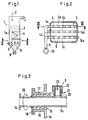
- the fluidized bed reactor (1) of Figure 1 can be different Serve purposes, e.g. B. the thermal treatment, in particular the Cool or heat granular solids through the line (2) can be fed.
- a fluidized bed (3) is located in the reactor, which is moved by the upward flowing fluidization medium.
- On Pipe system (4) is in a manner known per se from one Heating or cooling fluid flows through to add or remove heat dissipate.
- the reactor housing (1a) has one in the lower area Nozzle grate (5), which consists of parallel tubes (5a), (5b) and (5c) exists, which are equipped with numerous nozzles (6), cf. in particular Figure 2.
- Fluidizing medium e.g. B. steam or any gas or Gas mixture
- Fluidizing medium is pressure from the outside of the nozzle grate (5) supplied, exits through the nozzles (6) and flows upwards the fluidized bed (3). Gases and vapors are exhausted through the duct (7) removed. Treated solids fall through the nozzle grate (5) in the collection bunker (8) underneath withdrawn downwards by a lock device (9).
- FIG. 2 shows a schematic view from above the grate (5).
- the fluidization medium is from the outside sucked the compressor (10) and first into the main line (11) pressed.
- the fluidization medium flows from the main line (11) into the tubes (5a), (5b) and (5c) and passes through their nozzles (6) into the fluidized bed (3).
- Figure 2 are the releasable Flange connections (14) between the ends of the tubes (5a) to (5c) and the main line (11) indicated; the detachable attachment the tubes on the reactor housing (1a) was the better one in FIG Clarity omitted.
- FIG. 3 Details of the releasable attachment between a tube (5a) and the reactor housing (1a) are shown in Figure 3.
- the housing opening (15) is a pipe socket with the reactor housing (16) connected, one between the nozzle and the tube (5a) Sealing (17) is arranged.
- Sealing (17) is arranged.
- An annular disc (18) is welded to the tube (5a), with the pipe socket (16) in a manner not shown, e.g. is releasably connected by screw bolts.
- analog Way the connection between the other, closed end (14a) of the tubes with the housing (1a).
- FIG. 3 shows a nozzle (6) which is connected to the tube (5a) is detachably connected.
- the tube has a threaded ring (20) into which the nozzle is screwed with its foot (21) is.
- the foot (21) is designed as a piece of pipe that at the upper end is completed by a cap (22).
- the foot has holes (23) through which the fluidization medium on the by the Arrow (24) indicated path in the fluidized bed (3) emerges.
Landscapes
- Chemical & Material Sciences (AREA)
- Organic Chemistry (AREA)
- Chemical Kinetics & Catalysis (AREA)
- Engineering & Computer Science (AREA)
- Combustion & Propulsion (AREA)
- Devices And Processes Conducted In The Presence Of Fluids And Solid Particles (AREA)
Claims (1)
- Réacteur à lit fluidisé comportant une grille de buses disposée dans la région inférieure de la cuve du réacteur pour l'introduction d'agent de fluidisation dans le réacteur, la grille de buse comportant plusieurs conduits s'étendant sensiblement horizontalement et munis de buses pour le passage de l'agent de fluidisation, un conduit ayant au moins une ouverture dans la cuve de réacteur et une tubulure entourant le conduit étant reliée à l'ouverture, le conduit étant relié à la tubulure de manière amovible, et celle-ci supportant le conduit lorsqu'on le fait tourner par rapport à son axe longitudinal, caractérisé en ce que les buses sont reliées à leurs conduits associés de manière amovible par vissage et la région du réacteur en dessous des conduits est formée de manière à être accessible à un utilisateur jusqu'aux buses lorsque le fonctionnement est arrêté, de manière à ce qu'un utilisateur se trouvant en-dessous des tubes puisse atteindre facilement les buses lorsque les conduits sont tournés par rapport à l'axe longitudinal et ainsi les buses sont tournées vers le bas.
Applications Claiming Priority (2)
| Application Number | Priority Date | Filing Date | Title |
|---|---|---|---|
| DE4301365 | 1993-01-20 | ||
| DE4301365A DE4301365A1 (de) | 1993-01-20 | 1993-01-20 | Wirbelschichtreaktor mit Düsenrost |
Publications (3)
| Publication Number | Publication Date |
|---|---|
| EP0607601A1 EP0607601A1 (fr) | 1994-07-27 |
| EP0607601B1 EP0607601B1 (fr) | 1997-01-29 |
| EP0607601B2 true EP0607601B2 (fr) | 2000-07-26 |
Family
ID=6478535
Family Applications (1)
| Application Number | Title | Priority Date | Filing Date |
|---|---|---|---|
| EP93120763A Expired - Lifetime EP0607601B2 (fr) | 1993-01-20 | 1993-12-23 | Réacteur à lit fluidifié pourvu d'une grille à buse |
Country Status (6)
| Country | Link |
|---|---|
| US (1) | US5401471A (fr) |
| EP (1) | EP0607601B2 (fr) |
| AU (1) | AU666996B2 (fr) |
| CA (1) | CA2112870A1 (fr) |
| DE (2) | DE4301365A1 (fr) |
| GR (1) | GR3022890T3 (fr) |
Families Citing this family (4)
| Publication number | Priority date | Publication date | Assignee | Title |
|---|---|---|---|---|
| JP3595435B2 (ja) * | 1997-08-04 | 2004-12-02 | 三菱重工業株式会社 | 粒子移動量制御装置 |
| US7987614B2 (en) * | 2004-04-12 | 2011-08-02 | Erickson Robert W | Restraining device for reducing warp in lumber during drying |
| AT505527B1 (de) * | 2007-07-20 | 2011-09-15 | Key Technologies Ind Gmbh | Reaktor |
| EP3160628B1 (fr) * | 2014-06-30 | 2020-08-05 | Haldor Topsøe A/S | Réacteur comprenant un collecteur de sortie pourvu d'un orifice d'inspection et d'un anneau de compression |
Citations (4)
| Publication number | Priority date | Publication date | Assignee | Title |
|---|---|---|---|---|
| US3892046A (en) † | 1973-06-08 | 1975-07-01 | Coal Industry Patents Ltd | Fluidised bed apparatus |
| EP0022913A1 (fr) † | 1979-07-24 | 1981-01-28 | Resicoat GmbH Beschichtungspulver | Dispositif pour fluidifier des poudres |
| DE3343480A1 (de) † | 1983-12-01 | 1985-06-13 | L. & C. Steinmüller GmbH, 5270 Gummersbach | Verfahren und vorrichtung zum fluidisieren und gleichzeitigen kuehlen von wirbelschichtmaterial in einer wirbelschicht-feuerung |
| DE3437486A1 (de) † | 1984-10-12 | 1986-04-17 | Cornel. Schmidt GmbH & Co KG, 5090 Leverkusen | Wirbelschichtfeuerung |
Family Cites Families (11)
| Publication number | Priority date | Publication date | Assignee | Title |
|---|---|---|---|---|
| US491549A (en) * | 1893-02-14 | Blast-pipe for furnace-grates | ||
| US692254A (en) * | 1901-10-05 | 1902-02-04 | Edward J Dolan | Gas-burner. |
| US993369A (en) * | 1909-09-07 | 1911-05-30 | Henrietta Hensel | Fire-kindler. |
| US2628158A (en) * | 1950-03-06 | 1953-02-10 | Sinclair Refining Co | Catalyst stripping vessel |
| US2781088A (en) * | 1952-11-20 | 1957-02-12 | William P Ayers | Multiple gas burner |
| US2841476A (en) * | 1953-07-16 | 1958-07-01 | Dorr Oliver Inc | Apparatus for contacting solids with gases |
| DE1065383B (de) * | 1957-12-21 | 1959-09-17 | Metallgesellschaft Aktiengesellschaft, Frankfurt/M., und Ruhrgas Aktiengesellschaft, Essen | Vorrichtung zum gleichmäßigen Verteilen von Flüssigkeiten, Gasen oder Dämpfen auf ein bewegtes Bett staubförmiger oder körniger heißer Feststoffe |
| US3918639A (en) * | 1974-09-19 | 1975-11-11 | Coen Co | Oil atomizer |
| US4241021A (en) * | 1979-05-14 | 1980-12-23 | Stauffer Chemical Company | Fluidized bed reactor system |
| US4292023A (en) * | 1979-08-01 | 1981-09-29 | Curtiss-Wright Corporation | Fluidized bed combustor and removable windbox and tube assembly therefor |
| US4378744A (en) * | 1979-08-01 | 1983-04-05 | Curtiss-Wright Corporation | Fluidized bed combustor and removable windbox and tube assembly therefor |
-
1993
- 1993-01-20 DE DE4301365A patent/DE4301365A1/de not_active Withdrawn
- 1993-12-14 US US08/166,436 patent/US5401471A/en not_active Expired - Lifetime
- 1993-12-23 EP EP93120763A patent/EP0607601B2/fr not_active Expired - Lifetime
- 1993-12-23 DE DE59305341T patent/DE59305341D1/de not_active Expired - Fee Related
-
1994
- 1994-01-05 CA CA002112870A patent/CA2112870A1/fr not_active Abandoned
- 1994-01-18 AU AU53833/94A patent/AU666996B2/en not_active Ceased
-
1997
- 1997-03-24 GR GR970400572T patent/GR3022890T3/el unknown
Patent Citations (4)
| Publication number | Priority date | Publication date | Assignee | Title |
|---|---|---|---|---|
| US3892046A (en) † | 1973-06-08 | 1975-07-01 | Coal Industry Patents Ltd | Fluidised bed apparatus |
| EP0022913A1 (fr) † | 1979-07-24 | 1981-01-28 | Resicoat GmbH Beschichtungspulver | Dispositif pour fluidifier des poudres |
| DE3343480A1 (de) † | 1983-12-01 | 1985-06-13 | L. & C. Steinmüller GmbH, 5270 Gummersbach | Verfahren und vorrichtung zum fluidisieren und gleichzeitigen kuehlen von wirbelschichtmaterial in einer wirbelschicht-feuerung |
| DE3437486A1 (de) † | 1984-10-12 | 1986-04-17 | Cornel. Schmidt GmbH & Co KG, 5090 Leverkusen | Wirbelschichtfeuerung |
Also Published As
| Publication number | Publication date |
|---|---|
| EP0607601A1 (fr) | 1994-07-27 |
| US5401471A (en) | 1995-03-28 |
| AU666996B2 (en) | 1996-02-29 |
| DE4301365A1 (de) | 1994-07-21 |
| CA2112870A1 (fr) | 1994-07-21 |
| AU5383394A (en) | 1994-07-28 |
| DE59305341D1 (de) | 1997-03-13 |
| GR3022890T3 (en) | 1997-06-30 |
| EP0607601B1 (fr) | 1997-01-29 |
Similar Documents
| Publication | Publication Date | Title |
|---|---|---|
| DE69017000T2 (de) | Methode und vorrichtung für ein teilchenauswechselsystem für gegenstromkontakt eines gasförmigen und eines flüssigen einsatzes mit einem schüttgutbett. | |
| DE2129974C3 (de) | Vorrichtung zur NaBreinigung von Reaktions- und Verbrennungsgasen | |
| DE10116892A1 (de) | Verfahren zum Fördern von körnigen Feststoffen | |
| DE2646130C3 (de) | Druckluftfördereinrichtung | |
| DE4118433C2 (de) | Fließbettapparatur zum Behandeln partikelförmigen Gutes | |
| EP0616022B1 (fr) | Procédé pour la gazéification sous pression de combustibles finement divisés | |
| EP0607601B2 (fr) | Réacteur à lit fluidifié pourvu d'une grille à buse | |
| DE2019210A1 (de) | Vorrichtung zur Abtrennung von Katalysatorteilchen | |
| DE1242188B (de) | Verfahren und Vorrichtung zur Kontaktbehandlung von Gasen mit Fluessigkeiten | |
| DE3208421A1 (de) | Vorrichtung zum kuehlen eines in einem vergaser erzeugten gases | |
| LU83161A1 (de) | Vorreinigungseinrichtung in druckausgleichleitungen von schachtoefen | |
| DE3434336A1 (de) | Stufenfoermiger stromverteilungsgitterplattenaufbau und verfahren fuer einen fliessbettreaktor | |
| CH630948A5 (de) | Anlage zur russherstellung. | |
| DE68903187T2 (de) | Wirbelschichtkessel. | |
| DE4302175C2 (de) | Strahlungskühler eines Gaserzeugers | |
| WO1996014918A1 (fr) | Adsorbeur pour epuration de gaz de combustion | |
| DE2414080C3 (de) | Flüssigkeitsfilter | |
| DE2905281A1 (de) | Anordnung fuer die zufuhr und verteilung von staubhaltigem gas | |
| DE3017825A1 (de) | Verfahren und vorrichtung zur abfuehrung von festkoerperpartikeln aus einem druckbehaelter | |
| DE2810887A1 (de) | Apparat zum kuehlen von industriellen gasen | |
| DE19518191C2 (de) | Verfahren und Entgasungsbehälter zum Entgasen von Faulschlamm | |
| DE1611322C (de) | Wasserkasten für Feuchtwerke von Offsetdruckmaschinen | |
| WO2000061704A1 (fr) | Installation de craquage catalytique fluide et clapet correspondant | |
| DE1916652C (de) | Verfahren und Vorrichtung zur Umwandlung von Kohlenwasserstoffen | |
| DE4128552A1 (de) | Vorrichtung zur zufuhr von luft in eine wirbelschichtfeuerung |
Legal Events
| Date | Code | Title | Description |
|---|---|---|---|
| PUAI | Public reference made under article 153(3) epc to a published international application that has entered the european phase |
Free format text: ORIGINAL CODE: 0009012 |
|
| AK | Designated contracting states |
Kind code of ref document: A1 Designated state(s): DE GR NL |
|
| 17P | Request for examination filed |
Effective date: 19940817 |
|
| 17Q | First examination report despatched |
Effective date: 19960327 |
|
| GRAG | Despatch of communication of intention to grant |
Free format text: ORIGINAL CODE: EPIDOS AGRA |
|
| GRAH | Despatch of communication of intention to grant a patent |
Free format text: ORIGINAL CODE: EPIDOS IGRA |
|
| GRAH | Despatch of communication of intention to grant a patent |
Free format text: ORIGINAL CODE: EPIDOS IGRA |
|
| RBV | Designated contracting states (corrected) |
Designated state(s): DE GR NL |
|
| GRAA | (expected) grant |
Free format text: ORIGINAL CODE: 0009210 |
|
| AK | Designated contracting states |
Kind code of ref document: B1 Designated state(s): DE GR NL |
|
| REF | Corresponds to: |
Ref document number: 59305341 Country of ref document: DE Date of ref document: 19970313 |
|
| REG | Reference to a national code |
Ref country code: GR Ref legal event code: FG4A Free format text: 3022890 |
|
| PLBQ | Unpublished change to opponent data |
Free format text: ORIGINAL CODE: EPIDOS OPPO |
|
| PLBI | Opposition filed |
Free format text: ORIGINAL CODE: 0009260 |
|
| PLBF | Reply of patent proprietor to notice(s) of opposition |
Free format text: ORIGINAL CODE: EPIDOS OBSO |
|
| 26 | Opposition filed |
Opponent name: BABCOCK-BSH GMBH Effective date: 19971025 |
|
| NLR1 | Nl: opposition has been filed with the epo |
Opponent name: BABCOCK-BSH GMBH |
|
| PLBF | Reply of patent proprietor to notice(s) of opposition |
Free format text: ORIGINAL CODE: EPIDOS OBSO |
|
| PGFP | Annual fee paid to national office [announced via postgrant information from national office to epo] |
Ref country code: NL Payment date: 19981123 Year of fee payment: 6 |
|
| PGFP | Annual fee paid to national office [announced via postgrant information from national office to epo] |
Ref country code: GR Payment date: 19981130 Year of fee payment: 6 |
|
| RAP2 | Party data changed (patent owner data changed or rights of a patent transferred) |
Owner name: METALLGESELLSCHAFT AKTIENGESELLSCHAFT |
|
| NLT2 | Nl: modifications (of names), taken from the european patent patent bulletin |
Owner name: METALLGESELLSCHAFT AKTIENGESELLSCHAFT |
|
| PLAW | Interlocutory decision in opposition |
Free format text: ORIGINAL CODE: EPIDOS IDOP |
|
| PLAW | Interlocutory decision in opposition |
Free format text: ORIGINAL CODE: EPIDOS IDOP |
|
| PG25 | Lapsed in a contracting state [announced via postgrant information from national office to epo] |
Ref country code: GR Free format text: LAPSE BECAUSE OF NON-PAYMENT OF DUE FEES Effective date: 19991231 |
|
| PUAH | Patent maintained in amended form |
Free format text: ORIGINAL CODE: 0009272 |
|
| STAA | Information on the status of an ep patent application or granted ep patent |
Free format text: STATUS: PATENT MAINTAINED AS AMENDED |
|
| PG25 | Lapsed in a contracting state [announced via postgrant information from national office to epo] |
Ref country code: NL Free format text: LAPSE BECAUSE OF NON-PAYMENT OF DUE FEES Effective date: 20000701 |
|
| 27A | Patent maintained in amended form |
Effective date: 20000726 |
|
| AK | Designated contracting states |
Kind code of ref document: B2 Designated state(s): DE GR NL |
|
| NLV4 | Nl: lapsed or anulled due to non-payment of the annual fee |
Effective date: 20000701 |
|
| PGFP | Annual fee paid to national office [announced via postgrant information from national office to epo] |
Ref country code: DE Payment date: 20071221 Year of fee payment: 15 |
|
| PG25 | Lapsed in a contracting state [announced via postgrant information from national office to epo] |
Ref country code: DE Free format text: LAPSE BECAUSE OF NON-PAYMENT OF DUE FEES Effective date: 20090701 |