EP0607601B2 - Fluidised bed reactor having a nozzle grating - Google Patents
Fluidised bed reactor having a nozzle grating Download PDFInfo
- Publication number
- EP0607601B2 EP0607601B2 EP93120763A EP93120763A EP0607601B2 EP 0607601 B2 EP0607601 B2 EP 0607601B2 EP 93120763 A EP93120763 A EP 93120763A EP 93120763 A EP93120763 A EP 93120763A EP 0607601 B2 EP0607601 B2 EP 0607601B2
- Authority
- EP
- European Patent Office
- Prior art keywords
- reactor
- nozzles
- pipe
- pipes
- nozzle
- Prior art date
- Legal status (The legal status is an assumption and is not a legal conclusion. Google has not performed a legal analysis and makes no representation as to the accuracy of the status listed.)
- Expired - Lifetime
Links
Images
Classifications
-
- B—PERFORMING OPERATIONS; TRANSPORTING
- B01—PHYSICAL OR CHEMICAL PROCESSES OR APPARATUS IN GENERAL
- B01J—CHEMICAL OR PHYSICAL PROCESSES, e.g. CATALYSIS OR COLLOID CHEMISTRY; THEIR RELEVANT APPARATUS
- B01J8/00—Chemical or physical processes in general, conducted in the presence of fluids and solid particles; Apparatus for such processes
- B01J8/18—Chemical or physical processes in general, conducted in the presence of fluids and solid particles; Apparatus for such processes with fluidised particles
- B01J8/1818—Feeding of the fluidising gas
-
- B—PERFORMING OPERATIONS; TRANSPORTING
- B01—PHYSICAL OR CHEMICAL PROCESSES OR APPARATUS IN GENERAL
- B01J—CHEMICAL OR PHYSICAL PROCESSES, e.g. CATALYSIS OR COLLOID CHEMISTRY; THEIR RELEVANT APPARATUS
- B01J8/00—Chemical or physical processes in general, conducted in the presence of fluids and solid particles; Apparatus for such processes
- B01J8/008—Details of the reactor or of the particulate material; Processes to increase or to retard the rate of reaction
Definitions
- the invention relates to a fluidized bed reactor with one in the bottom Area of the reactor housing arranged nozzle grate for insertion of fluidizing medium into the reactor, the nozzle grate several, approximately horizontal pipes with nozzles for the Has passage of the fluidizing medium, at least to a tube an opening in the reactor housing belongs and with the opening a pipe socket surrounding the pipe is connected, with which the Pipe is detachably connected and supports the pipe when you move it around rotates its longitudinal axis.
- Fluidized bed reactors of this type are known from DE-B-1 065 383.
- the nozzles are designed as openings in the tubes. Similar tubes with openings are known from US-A-2 682 158 and EP-A-0 019 422 known.
- the invention has for its object the nozzle grate training to be easy to maintain and also convenient To allow replacement of the nozzles. In the fluidized bed reactor mentioned at the beginning the task according to the invention by the features of the license plate of the claim solved.
- the fluidized bed reactor (1) of Figure 1 can be different Serve purposes, e.g. B. the thermal treatment, in particular the Cool or heat granular solids through the line (2) can be fed.
- a fluidized bed (3) is located in the reactor, which is moved by the upward flowing fluidization medium.
- On Pipe system (4) is in a manner known per se from one Heating or cooling fluid flows through to add or remove heat dissipate.
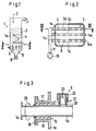
- the reactor housing (1a) has one in the lower area Nozzle grate (5), which consists of parallel tubes (5a), (5b) and (5c) exists, which are equipped with numerous nozzles (6), cf. in particular Figure 2.
- Fluidizing medium e.g. B. steam or any gas or Gas mixture
- Fluidizing medium is pressure from the outside of the nozzle grate (5) supplied, exits through the nozzles (6) and flows upwards the fluidized bed (3). Gases and vapors are exhausted through the duct (7) removed. Treated solids fall through the nozzle grate (5) in the collection bunker (8) underneath withdrawn downwards by a lock device (9).
- FIG. 2 shows a schematic view from above the grate (5).
- the fluidization medium is from the outside sucked the compressor (10) and first into the main line (11) pressed.
- the fluidization medium flows from the main line (11) into the tubes (5a), (5b) and (5c) and passes through their nozzles (6) into the fluidized bed (3).
- Figure 2 are the releasable Flange connections (14) between the ends of the tubes (5a) to (5c) and the main line (11) indicated; the detachable attachment the tubes on the reactor housing (1a) was the better one in FIG Clarity omitted.
- FIG. 3 Details of the releasable attachment between a tube (5a) and the reactor housing (1a) are shown in Figure 3.
- the housing opening (15) is a pipe socket with the reactor housing (16) connected, one between the nozzle and the tube (5a) Sealing (17) is arranged.
- Sealing (17) is arranged.
- An annular disc (18) is welded to the tube (5a), with the pipe socket (16) in a manner not shown, e.g. is releasably connected by screw bolts.
- analog Way the connection between the other, closed end (14a) of the tubes with the housing (1a).
- FIG. 3 shows a nozzle (6) which is connected to the tube (5a) is detachably connected.
- the tube has a threaded ring (20) into which the nozzle is screwed with its foot (21) is.
- the foot (21) is designed as a piece of pipe that at the upper end is completed by a cap (22).
- the foot has holes (23) through which the fluidization medium on the by the Arrow (24) indicated path in the fluidized bed (3) emerges.
Landscapes
- Chemical & Material Sciences (AREA)
- Organic Chemistry (AREA)
- Chemical Kinetics & Catalysis (AREA)
- Engineering & Computer Science (AREA)
- Combustion & Propulsion (AREA)
- Devices And Processes Conducted In The Presence Of Fluids And Solid Particles (AREA)
Description
Die Erfindung betrifft einen Wirbelschichtreaktor mit einem im unteren Bereich des Reaktorgehäuses angeordneten Düsenrost zum Einführen von Fluidisierungsmedium in den Reaktor, wobei der Düsenrost mehrere, etwa horizontal verlaufende Rohre mit Düsen für den Durchtritt des Fluidisierungsmediums aufweist, zu einem Rohr mindestens eine Öffnung im Reaktorgehäuse gehört und mit der Öffnung ein das Rohr umgebender Rohrstutzen verbunden ist, mit welchem das Rohr lösbar verbunden ist und der das Rohr stützt, wenn man es um seine Längsachsedreht.The invention relates to a fluidized bed reactor with one in the bottom Area of the reactor housing arranged nozzle grate for insertion of fluidizing medium into the reactor, the nozzle grate several, approximately horizontal pipes with nozzles for the Has passage of the fluidizing medium, at least to a tube an opening in the reactor housing belongs and with the opening a pipe socket surrounding the pipe is connected, with which the Pipe is detachably connected and supports the pipe when you move it around rotates its longitudinal axis.
Wirbelschichtreaktoren dieser Art sind aus DE-B-1 065 383 bekannt. Hierbei sind die Düsen als Öffnungen in den Rohren ausgebildet. Ähnliche Rohre mit Öffnungen sind aus US-A-2 682 158 und EP-A-0 019 422 bekannt. Der Erfindung liegt die Aufgabe zugrunde, den Düsenrost wartungsfreundlich auszubilden und dabei auch ein bequemes Auswechseln der Düsen zu ermöglichen. Beim eingangs genannten Wirbelschichtreaktor wird die Aufgabe erfindungsgemäß durch die Merkmale des Kennzeichens des Patentanspruchs gelöst.Fluidized bed reactors of this type are known from DE-B-1 065 383. Here, the nozzles are designed as openings in the tubes. Similar tubes with openings are known from US-A-2 682 158 and EP-A-0 019 422 known. The invention has for its object the nozzle grate training to be easy to maintain and also convenient To allow replacement of the nozzles. In the fluidized bed reactor mentioned at the beginning the task according to the invention by the features of the license plate of the claim solved.
Durch die erfindungsgemäße Ausbildung der Rohre und durch die Stützvorrichtung wird es möglich, bei Montage- und Wartungsarbeiten die Düsen auf einfache Weise nicht nur von oben, sondern auch von unten her zu erreichen. Üblicherweise werden die lösbaren Verbindungen zwischen den Rohren und dem Reaktorgehäuse als Schraubverbindungen ausgebildet, doch sind auch andere lösbare Verbindungen, z.B. Klemmverbindungen, möglich.By the inventive design of the tubes and by Support device becomes possible during assembly and maintenance work the nozzles in a simple way not only from above, but also to reach from below. Usually the detachable connections between the tubes and the reactor housing as screw connections trained, but there are other detachable connections, e.g. Clamp connections, possible.
Ausgestaltungsmöglichkeiten des Wirbelschichtreaktors werden mit
Hilfe der Zeichnung erläutert. Es zeigt:
Der Wirbelschichtreaktor (1) der Figur 1 kann verschiedenen Zwecken dienen, z. B. der thermischen Behandlung, insbesondere dem Kühlen oder Erhitzen körniger Feststoffe, die durch die Leitung (2) zugeführt werden. Im Reaktor befindet sich ein Wirbelbett (3), das von aufwärts strömendem Fluidisierungsmedium bewegt wird. Ein Rohrleitungssystem (4) wird in an sich bekannter Weise von einem Heizungs- oder Kühlfluid durchströmt, um Wärme zu- oder abzuführen. Das Reaktorgehäuse (1a) weist im unteren Bereich einen Düsenrost (5) auf, der aus parallelen Rohren (5a), (5b) und (5c) besteht, die mit zahlreichen Düsen (6) bestückt sind, vgl. insbesondere Figur 2.The fluidized bed reactor (1) of Figure 1 can be different Serve purposes, e.g. B. the thermal treatment, in particular the Cool or heat granular solids through the line (2) can be fed. A fluidized bed (3) is located in the reactor, which is moved by the upward flowing fluidization medium. On Pipe system (4) is in a manner known per se from one Heating or cooling fluid flows through to add or remove heat dissipate. The reactor housing (1a) has one in the lower area Nozzle grate (5), which consists of parallel tubes (5a), (5b) and (5c) exists, which are equipped with numerous nozzles (6), cf. in particular Figure 2.
Fluidierungsmedium, z. B. Wasserdampf oder ein beliebiges Gas oder Gasgemisch, wird von außen unter Druck dem Düsenrost (5) zugeführt, tritt durch die Düsen (6) aus und strömt aufwärts durch das Wirbelbett (3). Gase und Dämpfe werden durch den Abzugskanal (7) entfernt. Behandelte Feststoffe fallen durch den Düsenrost (5) in den darunter befindlichen Sammelbunker (8) und werden durch eine Schleusenvorrichtung (9) nach unten abgezogen.Fluidizing medium, e.g. B. steam or any gas or Gas mixture, is pressure from the outside of the nozzle grate (5) supplied, exits through the nozzles (6) and flows upwards the fluidized bed (3). Gases and vapors are exhausted through the duct (7) removed. Treated solids fall through the nozzle grate (5) in the collection bunker (8) underneath withdrawn downwards by a lock device (9).
Figur 2 zeigt in schematischer Darstellung eine Sicht von oben auf den Düsenrost (5). Das Fluidisierungsmedium wird von außen durch den Verdichter (10) angesaugt und zunächst in die Hauptleitung (11) gedrückt. Von der Hauptleitung (11) strömt das Fluidisierungsmedium in die Rohre (5a), (5b) und (5c) und tritt durch deren Düsen (6) hindurch in das Wirbelbett (3) aus. In Figur 2 sind die lösbaren Flanschverbindungen (14) zwischen den Enden der Rohre (5a) bis (5c) und der Hauptleitung (11) angedeutet; die lösbare Befestigung der Rohre am Reaktorgehäuse (1a) wurde in Figur 2 aber der besseren Übersichtlichkeit wegen weggelassen.Figure 2 shows a schematic view from above the grate (5). The fluidization medium is from the outside sucked the compressor (10) and first into the main line (11) pressed. The fluidization medium flows from the main line (11) into the tubes (5a), (5b) and (5c) and passes through their nozzles (6) into the fluidized bed (3). In Figure 2 are the releasable Flange connections (14) between the ends of the tubes (5a) to (5c) and the main line (11) indicated; the detachable attachment the tubes on the reactor housing (1a) was the better one in FIG Clarity omitted.
Einzelheiten der lösbaren Befestigung zwischen einem Rohr (5a) und dem Reaktorgehäuse (1a) sind in Figur 3 dargestellt. Im Bereich der Gehäuseöffnung (15) ist mit dem Reaktorgehäuse ein Rohrstutzen (16) verbunden, wobei zwischen dem Stutzen und dem Rohr (5a) eine Abdichtung (17) angeordnet ist. Als Abdichtung kommt z.B. eine Stopfbuchse in Frage. Am Rohr (5a) ist eine Ringscheibe (18) angeschweißt, die mit dem Rohrstutzen (16) in nicht dargestellter Weise, z.B. durch Schraubbolzen, lösbar verbunden ist. In analoger Weise kann die Verbindung zwischen dem anderen, geschlossenen Ende (14a) der Rohre mit dem Gehäuse (1a) ausgebildet sein.Details of the releasable attachment between a tube (5a) and the reactor housing (1a) are shown in Figure 3. In the area the housing opening (15) is a pipe socket with the reactor housing (16) connected, one between the nozzle and the tube (5a) Sealing (17) is arranged. As a seal comes e.g. a Stuffing box in question. An annular disc (18) is welded to the tube (5a), with the pipe socket (16) in a manner not shown, e.g. is releasably connected by screw bolts. In analog Way, the connection between the other, closed end (14a) of the tubes with the housing (1a).
In Figur 3 ist eine Düse (6) dargestellt, die mit dem Rohr (5a) lösbar verbunden ist. Zu diesem Zweck weist das Rohr einen Gewindering (20) auf, in den die Düse mit ihrem Fuß (21) eingeschraubt ist. Der Fuß (21) ist als Rohrstück ausgebildet, das am oberen Ende durch eine Kappe (22) abgeschlossen ist. Der Fuß weist Löcher (23) auf, durch die das Fluidisierungsmedium auf dem durch den Pfeil (24) angedeuteten Weg in das Wirbelbett (3) austritt. FIG. 3 shows a nozzle (6) which is connected to the tube (5a) is detachably connected. For this purpose, the tube has a threaded ring (20) into which the nozzle is screwed with its foot (21) is. The foot (21) is designed as a piece of pipe that at the upper end is completed by a cap (22). The foot has holes (23) through which the fluidization medium on the by the Arrow (24) indicated path in the fluidized bed (3) emerges.
Für Montage- oder Wartungsarbeiten kann eine Bedienungsperson von unten, d.h. vom Sammelbunker (8) aus (vgl. Figur 1) die nach unten gedrehten Düsen erreichen. Zu diesem Zweck wird das zugehörige Rohr (5a) durch Lösen der Verbindung (14) zur Hauptleitung (11) und durch Lösen der Verbindung zwischen der Ringscheibe (18) und dem Rohrstutzen (16) drehbar gemacht. Man dreht das so beweglich gemachte Rohr (5a) um seine Längsachse, wie das in Figur 3 durch den gebogenen Pfeil (25) angedeutet ist. Diese Wartungsarbeiten erfolgen bei leerem Reaktor, d.h. ohne Vorhandensein eines Wirbelbettes (3). Ist das Rohr (5a) um 180° gegenüber der Darstellung in Figur 3 gedreht, so weist die Düse (6) nach unten und kann von einer unterhalb des Rohrs (5a) befindlichen Bedienungsperson leicht erreicht werden, um die Düse z.B. zu reinigen oder auszuwechseln. Durch die Abdichtung (17) wird dieses Drehen des Rohres (5a) nicht behindert.For installation or maintenance work, an operator from below, i.e. from the collecting bunker (8) (see FIG. 1) downwards reach rotated nozzles. For this purpose, the associated Pipe (5a) by loosening the connection (14) to the main line (11) and by loosening the connection between the washer (18) and made the pipe socket (16) rotatable. You turn it so flexibly made tube (5a) about its longitudinal axis, like that in Figure 3 by the curved arrow (25) is indicated. This maintenance work take place when the reactor is empty, i.e. without the presence of a fluidized bed (3). Is the tube (5a) by 180 ° compared to the illustration in Figure 3 rotated, the nozzle (6) points downwards and can from one operator located below the tube (5a) easily can be reached to the nozzle e.g. to clean or replace. Due to the seal (17) this turning of the tube (5a) is not with special needs.
Claims (1)
- A fluidised-bed reactor having a nozzle grate arranged in the lower region of the reactor housing for introducing fluidising medium into the reactor, the jet bank having a plurality of pipes extending approximately horizontally with nozzles for the fluidising medium to pass through, at least one opening in the reactor housing belonging to a pipe, and a pipe socket surrounding the pipe being connected to the opening, to which socket the pipe is detachably connected and which socket supports the pipe when it is rotated about its longitudinal axis, characterized in that the nozzles are detachably connected to the associated pipes by screwing and the region of the reactor beneath the pipes up to the nozzles is designed to be accessible to an operator when the reactor is not in operation such that when the pipes have been rotated about their longitudinal axis and the nozzles are turned downwards, the nozzles are easily accessible for an operator disposed beneath the pipes.
Applications Claiming Priority (2)
| Application Number | Priority Date | Filing Date | Title |
|---|---|---|---|
| DE4301365A DE4301365A1 (en) | 1993-01-20 | 1993-01-20 | Fluidized bed reactor with nozzle grate |
| DE4301365 | 1993-01-20 |
Publications (3)
| Publication Number | Publication Date |
|---|---|
| EP0607601A1 EP0607601A1 (en) | 1994-07-27 |
| EP0607601B1 EP0607601B1 (en) | 1997-01-29 |
| EP0607601B2 true EP0607601B2 (en) | 2000-07-26 |
Family
ID=6478535
Family Applications (1)
| Application Number | Title | Priority Date | Filing Date |
|---|---|---|---|
| EP93120763A Expired - Lifetime EP0607601B2 (en) | 1993-01-20 | 1993-12-23 | Fluidised bed reactor having a nozzle grating |
Country Status (6)
| Country | Link |
|---|---|
| US (1) | US5401471A (en) |
| EP (1) | EP0607601B2 (en) |
| AU (1) | AU666996B2 (en) |
| CA (1) | CA2112870A1 (en) |
| DE (2) | DE4301365A1 (en) |
| GR (1) | GR3022890T3 (en) |
Families Citing this family (4)
| Publication number | Priority date | Publication date | Assignee | Title |
|---|---|---|---|---|
| JP3595435B2 (en) * | 1997-08-04 | 2004-12-02 | 三菱重工業株式会社 | Particle movement control device |
| US7987614B2 (en) * | 2004-04-12 | 2011-08-02 | Erickson Robert W | Restraining device for reducing warp in lumber during drying |
| AT505527B1 (en) * | 2007-07-20 | 2011-09-15 | Key Technologies Ind Gmbh | REACTOR |
| CN106457183B (en) | 2014-06-30 | 2020-03-17 | 托普索公司 | Reactor comprising an outlet collector with inspection ports |
Citations (4)
| Publication number | Priority date | Publication date | Assignee | Title |
|---|---|---|---|---|
| US3892046A (en) † | 1973-06-08 | 1975-07-01 | Coal Industry Patents Ltd | Fluidised bed apparatus |
| EP0022913A1 (en) † | 1979-07-24 | 1981-01-28 | Resicoat GmbH Beschichtungspulver | Device for fluidising powdery material |
| DE3343480A1 (en) † | 1983-12-01 | 1985-06-13 | L. & C. Steinmüller GmbH, 5270 Gummersbach | Process and apparatus for the fluidising and simultaneous cooling of fluidised bed material in a fluidised bed furnace |
| DE3437486A1 (en) † | 1984-10-12 | 1986-04-17 | Cornel. Schmidt GmbH & Co KG, 5090 Leverkusen | Fluidized bed firing |
Family Cites Families (11)
| Publication number | Priority date | Publication date | Assignee | Title |
|---|---|---|---|---|
| US491549A (en) * | 1893-02-14 | Blast-pipe for furnace-grates | ||
| US692254A (en) * | 1901-10-05 | 1902-02-04 | Edward J Dolan | Gas-burner. |
| US993369A (en) * | 1909-09-07 | 1911-05-30 | Henrietta Hensel | Fire-kindler. |
| US2628158A (en) * | 1950-03-06 | 1953-02-10 | Sinclair Refining Co | Catalyst stripping vessel |
| US2781088A (en) * | 1952-11-20 | 1957-02-12 | William P Ayers | Multiple gas burner |
| US2841476A (en) * | 1953-07-16 | 1958-07-01 | Dorr Oliver Inc | Apparatus for contacting solids with gases |
| DE1065383B (en) * | 1957-12-21 | 1959-09-17 | Metallgesellschaft Aktiengesellschaft, Frankfurt/M., und Ruhrgas Aktiengesellschaft, Essen | Device for the even distribution of liquids, gases or vapors on a moving bed of hot powdery or granular solids |
| US3918639A (en) * | 1974-09-19 | 1975-11-11 | Coen Co | Oil atomizer |
| US4241021A (en) * | 1979-05-14 | 1980-12-23 | Stauffer Chemical Company | Fluidized bed reactor system |
| US4378744A (en) * | 1979-08-01 | 1983-04-05 | Curtiss-Wright Corporation | Fluidized bed combustor and removable windbox and tube assembly therefor |
| US4292023A (en) * | 1979-08-01 | 1981-09-29 | Curtiss-Wright Corporation | Fluidized bed combustor and removable windbox and tube assembly therefor |
-
1993
- 1993-01-20 DE DE4301365A patent/DE4301365A1/en not_active Withdrawn
- 1993-12-14 US US08/166,436 patent/US5401471A/en not_active Expired - Lifetime
- 1993-12-23 EP EP93120763A patent/EP0607601B2/en not_active Expired - Lifetime
- 1993-12-23 DE DE59305341T patent/DE59305341D1/en not_active Expired - Fee Related
-
1994
- 1994-01-05 CA CA002112870A patent/CA2112870A1/en not_active Abandoned
- 1994-01-18 AU AU53833/94A patent/AU666996B2/en not_active Ceased
-
1997
- 1997-03-24 GR GR970400572T patent/GR3022890T3/en unknown
Patent Citations (4)
| Publication number | Priority date | Publication date | Assignee | Title |
|---|---|---|---|---|
| US3892046A (en) † | 1973-06-08 | 1975-07-01 | Coal Industry Patents Ltd | Fluidised bed apparatus |
| EP0022913A1 (en) † | 1979-07-24 | 1981-01-28 | Resicoat GmbH Beschichtungspulver | Device for fluidising powdery material |
| DE3343480A1 (en) † | 1983-12-01 | 1985-06-13 | L. & C. Steinmüller GmbH, 5270 Gummersbach | Process and apparatus for the fluidising and simultaneous cooling of fluidised bed material in a fluidised bed furnace |
| DE3437486A1 (en) † | 1984-10-12 | 1986-04-17 | Cornel. Schmidt GmbH & Co KG, 5090 Leverkusen | Fluidized bed firing |
Also Published As
| Publication number | Publication date |
|---|---|
| US5401471A (en) | 1995-03-28 |
| DE59305341D1 (en) | 1997-03-13 |
| CA2112870A1 (en) | 1994-07-21 |
| DE4301365A1 (en) | 1994-07-21 |
| AU666996B2 (en) | 1996-02-29 |
| EP0607601A1 (en) | 1994-07-27 |
| AU5383394A (en) | 1994-07-28 |
| GR3022890T3 (en) | 1997-06-30 |
| EP0607601B1 (en) | 1997-01-29 |
Similar Documents
| Publication | Publication Date | Title |
|---|---|---|
| DE2129974C3 (en) | Device for wet cleaning of reaction and combustion gases | |
| DE3411757C2 (en) | Grid plate construction for a fluidized bed reactor | |
| DE10116892A1 (en) | Process for conveying granular solids | |
| DE2646130C3 (en) | Compressed air delivery device | |
| DE4118433C2 (en) | Fluid bed apparatus for treating particulate goods | |
| EP0616022B1 (en) | Process for pressure gasification of fine particulate fuels | |
| EP0607601B2 (en) | Fluidised bed reactor having a nozzle grating | |
| DE1242188B (en) | Method and device for the contact treatment of gases with liquids | |
| DE3208421A1 (en) | DEVICE FOR COOLING A GAS PRODUCED IN A CARBURETOR | |
| LU83161A1 (en) | PRE-CLEANING DEVICE IN PRESSURE COMPENSATION PIPES OF SHAFT OVENS | |
| DE3434336A1 (en) | STEPPED POWER DISTRIBUTION GRID PLATE STRUCTURE AND METHOD FOR A FLUID BED REACTOR | |
| CH630948A5 (en) | SOOT PRODUCTION PLANT. | |
| DE2623705A1 (en) | DISCHARGE DEVICE FOR SCHUETTGUETER | |
| DE4302175C2 (en) | Radiation cooler of a gas generator | |
| DE2414080C3 (en) | Liquid filter | |
| DE2905281A1 (en) | ARRANGEMENT FOR THE SUPPLY AND DISTRIBUTION OF DUSTIC GAS | |
| DE3017825A1 (en) | METHOD AND DEVICE FOR REMOVING SOLID PARTICLES FROM A PRESSURE TANK | |
| DE2810887A1 (en) | Cooler for industrial gas streams - using natural circulation boiler with faller tubes, mounted inside riser tubes exposed to hot gases, passing through collection space | |
| WO1996014918A1 (en) | Adsorber for purifying combustion gases | |
| DE19518191C2 (en) | Process and degassing tank for degassing digested sludge | |
| DE1611322C (en) | Water tank for dampening systems in offset printing machines | |
| WO2000061704A1 (en) | Fluid catalytic cracking facility and flap valve for said facility | |
| DE1916652C (en) | Process and device for the conversion of hydrocarbons | |
| DE4128552A1 (en) | Supply of air to fluidised bed - by using grid formed of pipes with nozzle openings in pipes | |
| DE2952800A1 (en) | Entrainment separator and gas-liquid contactor |
Legal Events
| Date | Code | Title | Description |
|---|---|---|---|
| PUAI | Public reference made under article 153(3) epc to a published international application that has entered the european phase |
Free format text: ORIGINAL CODE: 0009012 |
|
| AK | Designated contracting states |
Kind code of ref document: A1 Designated state(s): DE GR NL |
|
| 17P | Request for examination filed |
Effective date: 19940817 |
|
| 17Q | First examination report despatched |
Effective date: 19960327 |
|
| GRAG | Despatch of communication of intention to grant |
Free format text: ORIGINAL CODE: EPIDOS AGRA |
|
| GRAH | Despatch of communication of intention to grant a patent |
Free format text: ORIGINAL CODE: EPIDOS IGRA |
|
| GRAH | Despatch of communication of intention to grant a patent |
Free format text: ORIGINAL CODE: EPIDOS IGRA |
|
| RBV | Designated contracting states (corrected) |
Designated state(s): DE GR NL |
|
| GRAA | (expected) grant |
Free format text: ORIGINAL CODE: 0009210 |
|
| AK | Designated contracting states |
Kind code of ref document: B1 Designated state(s): DE GR NL |
|
| REF | Corresponds to: |
Ref document number: 59305341 Country of ref document: DE Date of ref document: 19970313 |
|
| REG | Reference to a national code |
Ref country code: GR Ref legal event code: FG4A Free format text: 3022890 |
|
| PLBQ | Unpublished change to opponent data |
Free format text: ORIGINAL CODE: EPIDOS OPPO |
|
| PLBI | Opposition filed |
Free format text: ORIGINAL CODE: 0009260 |
|
| PLBF | Reply of patent proprietor to notice(s) of opposition |
Free format text: ORIGINAL CODE: EPIDOS OBSO |
|
| 26 | Opposition filed |
Opponent name: BABCOCK-BSH GMBH Effective date: 19971025 |
|
| NLR1 | Nl: opposition has been filed with the epo |
Opponent name: BABCOCK-BSH GMBH |
|
| PLBF | Reply of patent proprietor to notice(s) of opposition |
Free format text: ORIGINAL CODE: EPIDOS OBSO |
|
| PGFP | Annual fee paid to national office [announced via postgrant information from national office to epo] |
Ref country code: NL Payment date: 19981123 Year of fee payment: 6 |
|
| PGFP | Annual fee paid to national office [announced via postgrant information from national office to epo] |
Ref country code: GR Payment date: 19981130 Year of fee payment: 6 |
|
| RAP2 | Party data changed (patent owner data changed or rights of a patent transferred) |
Owner name: METALLGESELLSCHAFT AKTIENGESELLSCHAFT |
|
| NLT2 | Nl: modifications (of names), taken from the european patent patent bulletin |
Owner name: METALLGESELLSCHAFT AKTIENGESELLSCHAFT |
|
| PLAW | Interlocutory decision in opposition |
Free format text: ORIGINAL CODE: EPIDOS IDOP |
|
| PLAW | Interlocutory decision in opposition |
Free format text: ORIGINAL CODE: EPIDOS IDOP |
|
| PG25 | Lapsed in a contracting state [announced via postgrant information from national office to epo] |
Ref country code: GR Free format text: LAPSE BECAUSE OF NON-PAYMENT OF DUE FEES Effective date: 19991231 |
|
| PUAH | Patent maintained in amended form |
Free format text: ORIGINAL CODE: 0009272 |
|
| STAA | Information on the status of an ep patent application or granted ep patent |
Free format text: STATUS: PATENT MAINTAINED AS AMENDED |
|
| PG25 | Lapsed in a contracting state [announced via postgrant information from national office to epo] |
Ref country code: NL Free format text: LAPSE BECAUSE OF NON-PAYMENT OF DUE FEES Effective date: 20000701 |
|
| 27A | Patent maintained in amended form |
Effective date: 20000726 |
|
| AK | Designated contracting states |
Kind code of ref document: B2 Designated state(s): DE GR NL |
|
| NLV4 | Nl: lapsed or anulled due to non-payment of the annual fee |
Effective date: 20000701 |
|
| PGFP | Annual fee paid to national office [announced via postgrant information from national office to epo] |
Ref country code: DE Payment date: 20071221 Year of fee payment: 15 |
|
| PG25 | Lapsed in a contracting state [announced via postgrant information from national office to epo] |
Ref country code: DE Free format text: LAPSE BECAUSE OF NON-PAYMENT OF DUE FEES Effective date: 20090701 |